ENGINE PERFORMANCE
4.2L
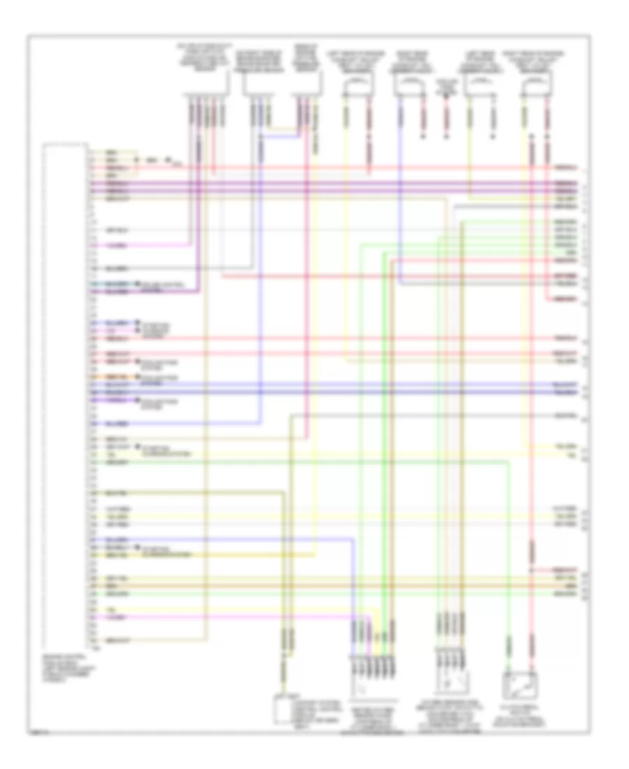
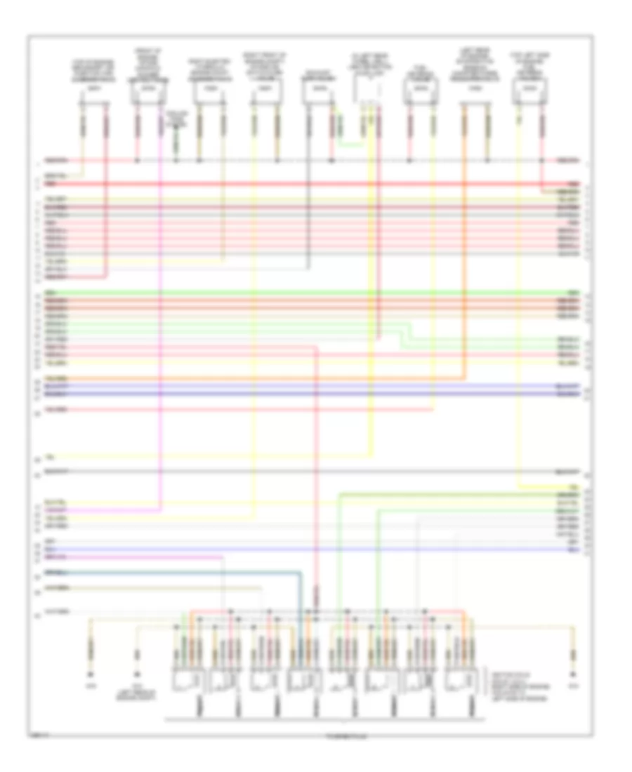
4.2L, Engine Performance Wiring Diagram (1 of 8) for Audi RS 4 2008
List of elements for 4.2L, Engine Performance Wiring Diagram (1 of 8) for Audi RS 4 2008:
- (left rear of engine) camshaft adj- ustment valve 2
- (left rear of engine) camshaft adjust- ment valve 2 (exhaust)
- (on air intake duct) mass air flow (maf)/intake air temperature (iat) sensor
- (on right side of brake booster) brake booster pressure sensor
- (rear of engine) low fuel pressure sensor
- (right rear of engine) camshaft adj- ustment valve 1
- (right rear of engine) camshaft adjust- ment valve 1 (exhaust)
- Clutch pedal switch (on clutch pedal mounting bracket)
- Comfort system central control module (below driver's seat)
- Cooling fans system
- Cruise control system
- Engine control module (ecm) (left engine compt plenum chamber, in e-box)
- G18
- Heated oxygen sensor (ho2s) (upstream of cylinder bank 1 catalytic converter)
- Nca
- Oxygen sensor (o2s) behind 3-way catalytic converter (twc) (downstream of cylinder bank 1 3-way catalytic converter)
- Starting/ charging system
- T12h
- T94
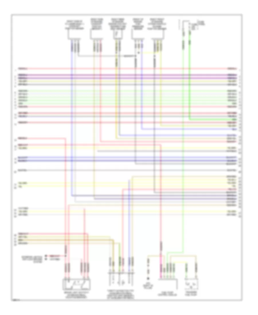
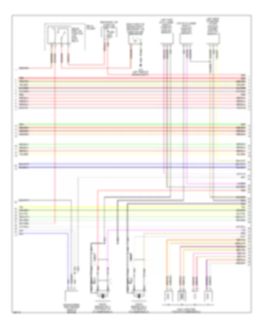
4.2L, Engine Performance Wiring Diagram (2 of 8) for Audi RS 4 2008
List of elements for 4.2L, Engine Performance Wiring Diagram (2 of 8) for Audi RS 4 2008:
- (front of engine) fuel pressure sensor
- (right front of engine) intake manifold runner position sensor
- (right rear of engine) engine coolant temperature (ect) sensor
- (right side of cylinder bank 1) camshaft position sensor
- (right side of engine) camshaft position sensor 3
- 228a
- Brake light switch f (on brake pedal mounting bracket)
- Exterior lights & anti-lock brakes system
- Fuel pump control module
- Fuse 30a
- Fuse panel
- G78 (right "b" pillar)
- Throttle position (tp)/ accelerator pedal position (app) sensor 2 (at accelerator pedal)
- Transfer fuel pump
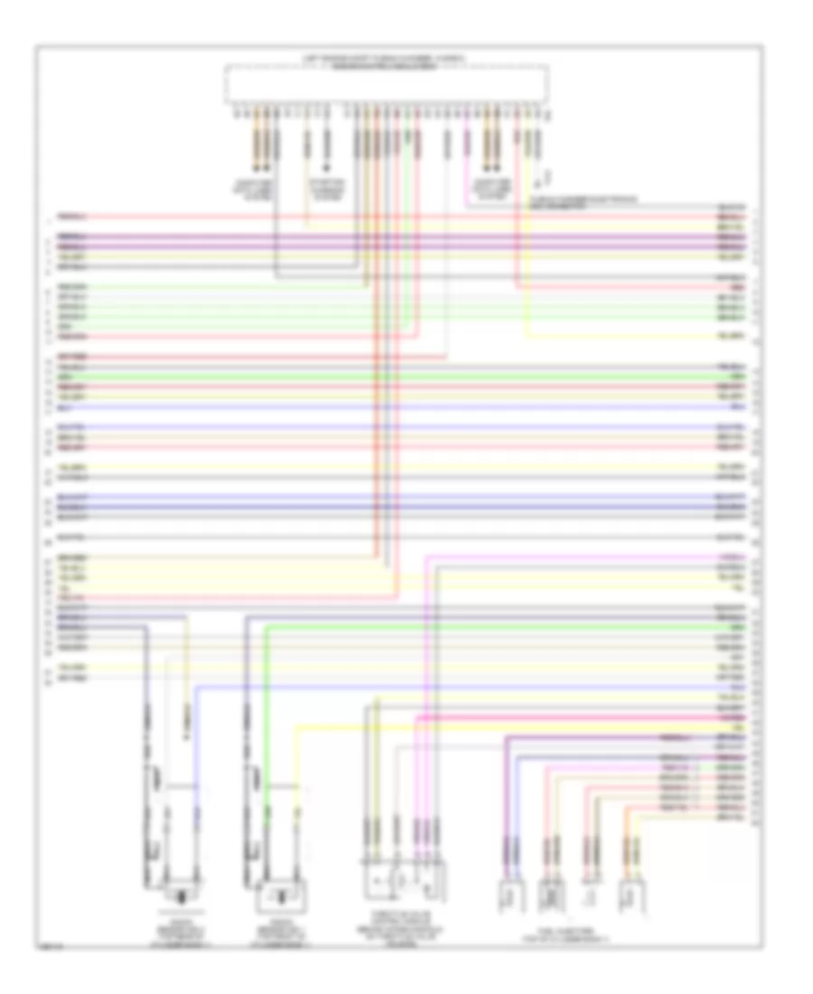
4.2L, Engine Performance Wiring Diagram (3 of 8) for Audi RS 4 2008
List of elements for 4.2L, Engine Performance Wiring Diagram (3 of 8) for Audi RS 4 2008:
- (left engine compt plenum chamber, in e-box) engine control module (ecm)
- Computer data lines system
- Fuel injectors (top of cylinder bank 1)
- Knock sensor (ks) 1 (top front of cylinder bank 1)
- Knock sensor (ks) 2 (top rear of cylinder bank 1)
- Nca
- Plenum chamber electronics box connector
- Red
- Starting/ charging system
- T17j
- T94
- Throttle valve control module (behind intake manifold, on throttle valve housing)
4.2L, Engine Performance Wiring Diagram (4 of 8) for Audi RS 4 2008
List of elements for 4.2L, Engine Performance Wiring Diagram (4 of 8) for Audi RS 4 2008:
- 14a
- 43a
- Brake vacuum pump fuse
- Cb 15a
- Engine control module (ecm) (left engine compt plenum chamber, in e-box)
- Engine control module fuse
- Engine electronics fuse 1
- Engine electronics fuse 2
- Fuse 10a
- Fuse 15a
- Fuse 30a
- Fuse holder
- Fuse holder/ relay panel
- Heated oxygen sensor circuit breaker
- Hot at all times
- Hot in run or start
- Red
- Safety fuse 1
- T60
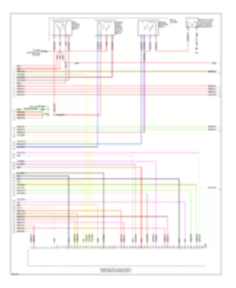
4.2L, Engine Performance Wiring Diagram (5 of 8) for Audi RS 4 2008
List of elements for 4.2L, Engine Performance Wiring Diagram (5 of 8) for Audi RS 4 2008:
- (front of engine) intake manifold runner control valve
- (in left rear wheel well) leak detection pump (ldp)
- (left rear of engine) evaporative emission canister purge regulator valve
- (right front of engine compt) intake air switch-over valve
- (top left side of engine) fuel metering valve 2
- (top of engine) secondary air injection (air) solenoid valve
- Cooling fans system
- Exhaust flap valve 1
- Fuel metering valve
- G12 (left rear of engine compt)
- G18
- G19
- Ignition coils (coils 1,2,3,4 : right side of engine) (coils 5,6,7,8 : left side of engine)
- Nca
- Red
- Right electro- hydraulic engine mount solenoid valve
- To spark plug
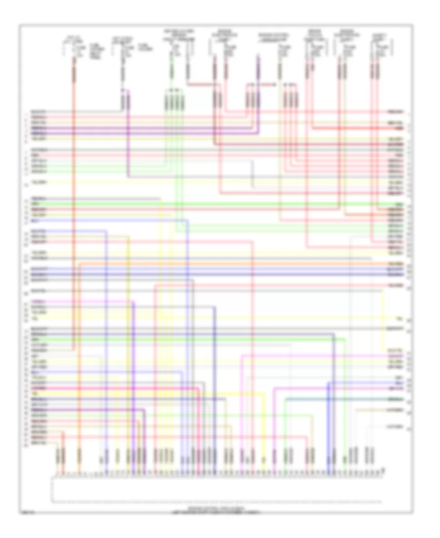
4.2L, Engine Performance Wiring Diagram (6 of 8) for Audi RS 4 2008
List of elements for 4.2L, Engine Performance Wiring Diagram (6 of 8) for Audi RS 4 2008:
- (left rear of engine) intake manifold runner position sensor 2
- (left side of cylinder bank 2) camshaft position sensor 4
- (right front of engine compt) secondary air injection (air) pump motor
- (top of cylinder bank 2) camshaft position sensor 2
- Engine speed (rpm) sensor (rear of engine)
- Fuel injectors (top of cylinder bank 2)
- Fuse 50a
- G12 (left rear of engine compt)
- Knock sensor (ks) 3 (top front of cylinder bank 2)
- Knock sensor (ks) 4 (top rear of cylinder bank 2)
- Nca
- Red
- Relay holder
- Secon- dary air injection (air) pump relay
- Secondary air injection pump fuse
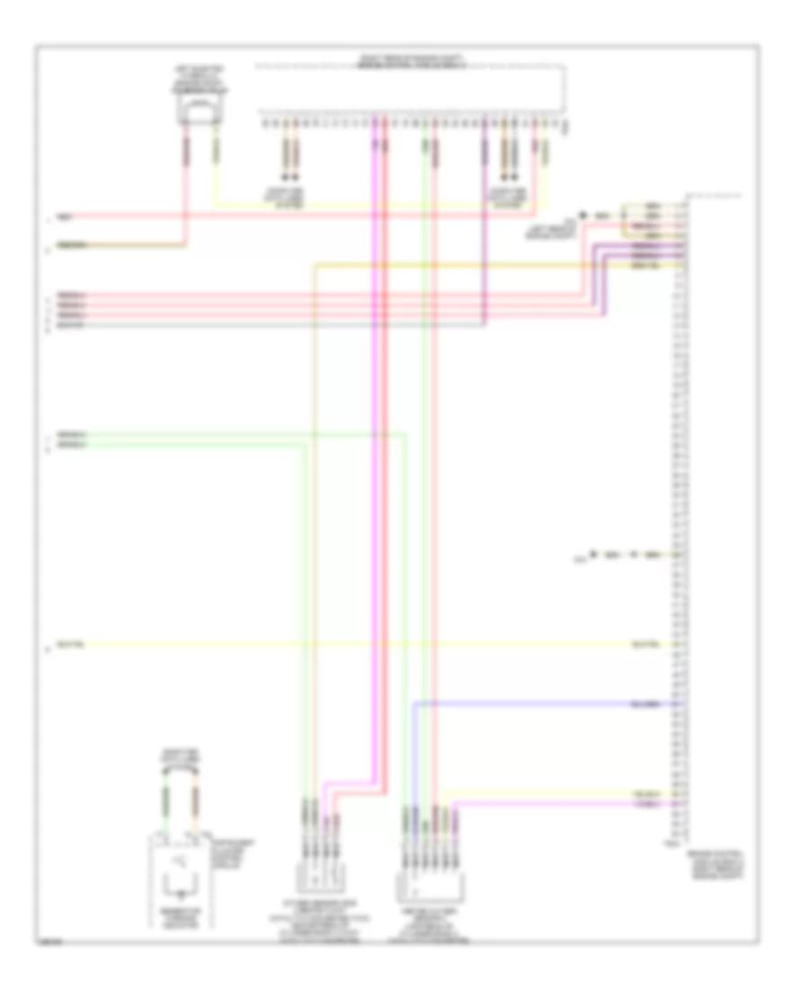
4.2L, Engine Performance Wiring Diagram (7 of 8) for Audi RS 4 2008
List of elements for 4.2L, Engine Performance Wiring Diagram (7 of 8) for Audi RS 4 2008:
- Brake booster relay
- Brake system vacuum pump (left side of engine compt)
- Cooling fans system
- Engine control module (ecm) 2 (right rear of engine compt)
- G18
- Power distribution system
- Red
- Relay holder
- T60a
4.2L, Engine Performance Wiring Diagram (8 of 8) for Audi RS 4 2008
List of elements for 4.2L, Engine Performance Wiring Diagram (8 of 8) for Audi RS 4 2008:
- (right rear of engine compt) engine control module (ecm) 2
- Computer data lines system
- Engine control module (ecm) 2 (right rear of engine compt)
- G12 (left rear of engine compt)
- G18
- Generator warning indicator
- Heated oxygen sensor 2 (upstream of cylinder bank 2 catalytic converter)
- Instrument cluster control module
- Left electro- hydraulic engine mount solenoid valve
- Nca
- Oxygen sensor (o2s) 2 behind 3-way catalytic converter (twc) (downstream of cylinder bank 2 3-way catalytic converter)
- Red
- T32
- T94a

 Čeština
 Dansk
Dansk Deutsch
 Ελληνικά
 English
 English
 Español
 Suomi
Suomi Français
 Français
 עברית
עברית Hrvatski
 Magyar
 日本語
日本語 한국어
한국어 Nederlands
 Polski
 Português
 Português
 Română
 Русский
 Slovenčina
 Slovenščina
 Svenska
 Türkçe
 中文 (中国)