POWER DISTRIBUTION
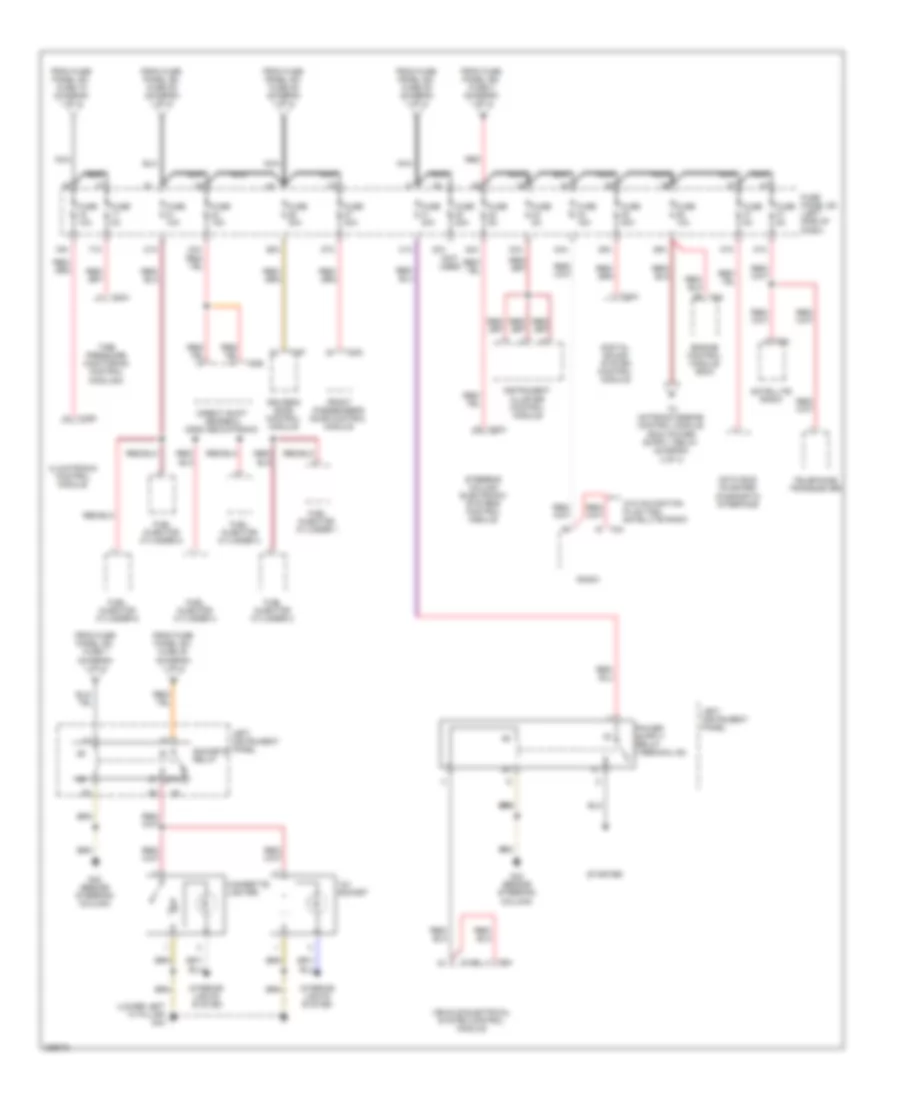
Power Distribution Wiring Diagram (1 of 4) for Audi TT 2008
 https://portal-diagnostov.com/license.html
Automotive Electricians Portal FZCO
Automotive Electricians Portal FZCO
https://portal-diagnostov.com/license.html
https://portal-diagnostov.com/license.html
Automotive Electricians Portal FZCO
Automotive Electricians Portal FZCO
List of elements for Power Distribution Wiring Diagram (1 of 4) for Audi TT 2008:
- (2.0l)
- (early production)
- (late production)
- (not used)
- 10a
- 11a
- 12a
- 13a
- 14a
- 15a
- 22a
- 23a
- 25a
- 29a
- 38a
- Abs control module
- Air bag control module
- All-wheel drive control module
- Asr/ esp button
- Automatic day/night interior mirror
- Backup light switch
- Battery
- Battery interrupt igniter
- Battery jump start terminal (if equipped)
- Brake light switch
- Coolant fan control module
- Data bus on board diagnostic interface
- Data link connector (16-pin)
- Data link connector (dlc) (16-pin)
- Driver's door control module
- Electronic damping control module
- From fuse panel sc, fuse 7 (diagram 1 of 4)
- Front interior light
- Front passenger's door control module
- Fuse
- Fuse 10a
- Fuse 110a
- Fuse 15a
- Fuse 175a
- Fuse 20a
- Fuse 30a
- Fuse 40a
- Fuse 5a
- Fuse 60a
- Fuse 80a
- Fuse panel sa (left side of engine compt)
- Fuse panel sc (left side of dash)
- Fuse panel sd (right side of luggage compt)
- G51 (right side of luggage compt)
- Generator
- Left headlamp assembly
- Left washer nozzle heater
- Light switch
- Mass air flow (maf) sensor
- Nca
- Oil level thermal sensor
- Power steering control module
- Rain/light recognition sensor (if equipped)
- Red
- Right headlamp assembly
- Right washer nozzle heater
- Seat occupied recognition control module
- Secondary air injection (air) pump relay
- Selector lever & tipronic switch (if equipped)
- Starter
- T10d
- T10e
- T10p
- T20f
- T20g
- T2s
- T2t
- T3l
- T5b
- T5e
- T6h
- T6n
- To circuit breaker (diagram 4 of 4)
- To fuse panel sc, fuse 16 (diagram 2 of 4)
- To fuse panel sc, fuse 21 (diagram 2 of 4)
- To fuse panel sc, fuse 26 (diagram 2 of 4)
- To fuse panel sc, fuse 31 (diagram 2 of 4)
- To fuse panel sc, fuse 32 (diagram 2 of 4)
- To fuse panel sc, fuse 8 (diagram 1 of 4)
- To fuse panel sf, fuse 1 (diagram 3 of 4)
- To left instrument panel, sockets relay (diagram 2 of 4)
- To suppressor (diagram 3 of 4)
- Vehicle electrical system control module
- Windshield washer pump
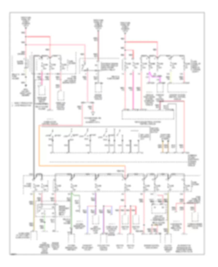
Power Distribution Wiring Diagram (2 of 4) for Audi TT 2008
List of elements for Power Distribution Wiring Diagram (2 of 4) for Audi TT 2008:
- (lower left "a" pillar) g44
- (not used)
- 12v socket
- 16a
- 17a
- 21a
- 24a
- 26a
- 27a
- 30a
- 31a
- 32a
- 33a
- 34a
- 35a
- 36a
- 37a
- 47a
- 87a
- Cigarette lighter
- Climatronic control module
- Data bus on board diagnostic interface
- Digital sound system control module
- Direct shift gearbox (dsg) mechatronic
- Driver's door control module
- Engine control module (ecm)
- From fuse panel sc, fuse 15 (diagram 1 of 4)
- From fuse panel sc, fuse 25 (diagram 1 of 4)
- From fuse panel sc, fuse 29 (diagram 1 of 4)
- From fuse panel sc, fuse 38 (diagram 1 of 4)
- From fuse panel sc, fuse 7 (diagram 1 of 4)
- From fuse panel sd, fuse 3 (diagram 1 of 4)
- Front passenger's door control module
- Fuel injector cylinder 1
- Fuel injector cylinder 2
- Fuel injector cylinder 3
- Fuel injector cylinder 4
- Fuel injector cylinder 5
- Fuel injector cylinder 6
- Fuse 10a
- Fuse 15a
- Fuse 20a
- Fuse 30a
- Fuse 40a
- Fuse 5a
- Fuse panel sc (left side of dash)
- G42 (beside steering column)
- Instrument cluster control module
- Interior lights system
- Left instrument panel
- Nca
- Nca nca
- Radio
- Red
- Satellite radio
- Sockets relay
- Starter
- Steering column electronic systems control module
- T11b
- T16d
- T20c
- T20f
- T20g
- T20h
- T32a
- T8a
- T8h
- T8m
- T94
- Telephone transceiver
- Tire pressure monitoring control module 2
- Vehicle electrical system control module
- W/o navigation plus (7q2), satellite radio
Power Distribution Wiring Diagram (3 of 4) for Audi TT 2008
List of elements for Power Distribution Wiring Diagram (3 of 4) for Audi TT 2008:
- (not used)
- 10a
- 11a
- 12a
- 2.0l
- 3.2l
- Alarm horn (w/ anti-theft alarm system)
- Camshaft adjustment valve 1
- Clutch position sensor (m/t)
- Comfort system central control module
- Computer data lines system
- Coolant circulation pump relay
- Coolant fan control module
- Early production
- Engine control module
- Engine control module (ecm)
- Evaporative emission (evap) canister purge regulator valve
- Fresh air blower control module
- From fuse panel sa, fuse 4 (diagram 1 of 4)
- From fuse panel sc, fuse 36 (diagram 2 of 4)
- From fuse panel sd, fuse 2 (diagram 1 of 4)
- Fuel pressure regulator valve (cdma engine)
- Fuse 10a
- Fuse 15a
- Fuse 20a
- Fuse 25a
- Fuse 30a
- Fuse 40a
- Fuse 5a
- Fuse fuse 5a
- Fuse holder
- Fuse panel sb (left side of engine compt)
- Fuse panel sf (right rear of luggage compt)
- G672 (on left front long member)
- Headlamp washer relay (if equipped)
- Ignition coil 1
- Ignition coil 2
- Ignition coil 3
- Ignition coil 4
- Ignition/ starter switch
- Key lock solenoid (a/t)
- Late production
- Leak detection pump (ldp)
- Lock
- Nca
- Over valve intake air switch (cdma engine)
- Oxygen sensor (o2s) heater 1
- Oxygen sensor (o2s) heater 2
- Parking aid control module
- Red
- Relay & fuse holder
- Run
- Start
- Steering column electronic systems control module
- Suppr- essor
- T11b
- T11c
- T12e
- T12i
- T12m
- T16e
- T18g
- T20c
- T4c
- T8h
- T94
- To fuse panel sb, fuse 8 (diagram 4 of 4)
- Turbocharger recalculating valve
- Vehicle electrical system control module
- Vehicle positioning system interface control module
- Wastegate bypass regulator valve
- Wiper motor control module
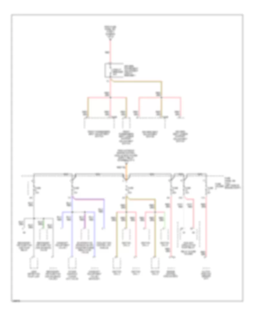
Power Distribution Wiring Diagram (4 of 4) for Audi TT 2008
List of elements for Power Distribution Wiring Diagram (4 of 4) for Audi TT 2008:
- 10a
- 11a
- Camshaft adjustment valve 1
- Camshaft adjustment valve 1 (exhaust)
- Circuit breaker 30a
- Clutch position sensor (m/t)
- Coolant circulation pump relay
- Coolant fan control (fc) module
- Driver's power seat adjustment circuit breaker 1
- Driver's seat adjustment switch
- Driver's seat lumbar support adjustment switch
- Engine control module (ecm)
- Evaporative emission (evap) canister purge regulator valve
- From fuse panel sd, fuse 3 (diagram 1 of 4)
- Front passenger's seat adjustment switch
- Front passenger's seat lumbar support adjustment switch
- Fuse 10a
- Fuse 25a
- Fuse 30a
- Fuse 5a
- Fuse holder
- Fuse panel sb (3.2l) (left side of engine compt)
- Ignition coil 1
- Ignition coil 2
- Ignition coil 3
- Ignition coil 4
- Ignition coil 5
- Ignition coil 6
- Intake manifold tuning (imt) valve
- Leak detection pump (ldp)
- Nca
- Red
- Relay & fuse holder
- Secondary air injection (air) pump relay
- Secondary air injection (air) solenoid valve
- Secondary air injection (air) solenoid valve 2
- T4ae
- T81

 Čeština
 Dansk
Dansk Deutsch
 Ελληνικά
 English
 English
 Español
 Suomi
Suomi Français
 Français
 עברית
עברית Hrvatski
 Magyar
 日本語
日本語 한국어
한국어 Nederlands
 Polski
 Português
 Português
 Română
 Русский
 Slovenčina
 Slovenščina
 Svenska
 Türkçe
 中文 (中国)