СИСТЕМА УПРАВЛЕНИЯ ДВИГАТЕЛЯ
4.6L
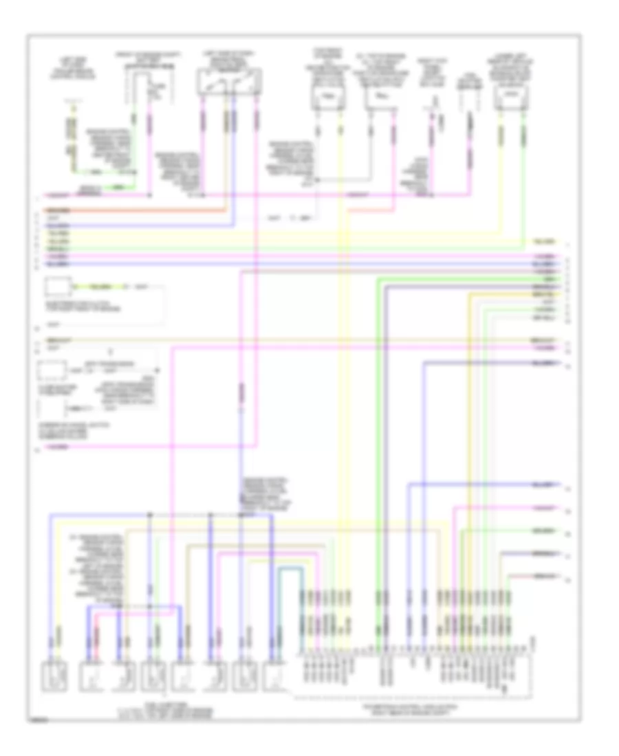
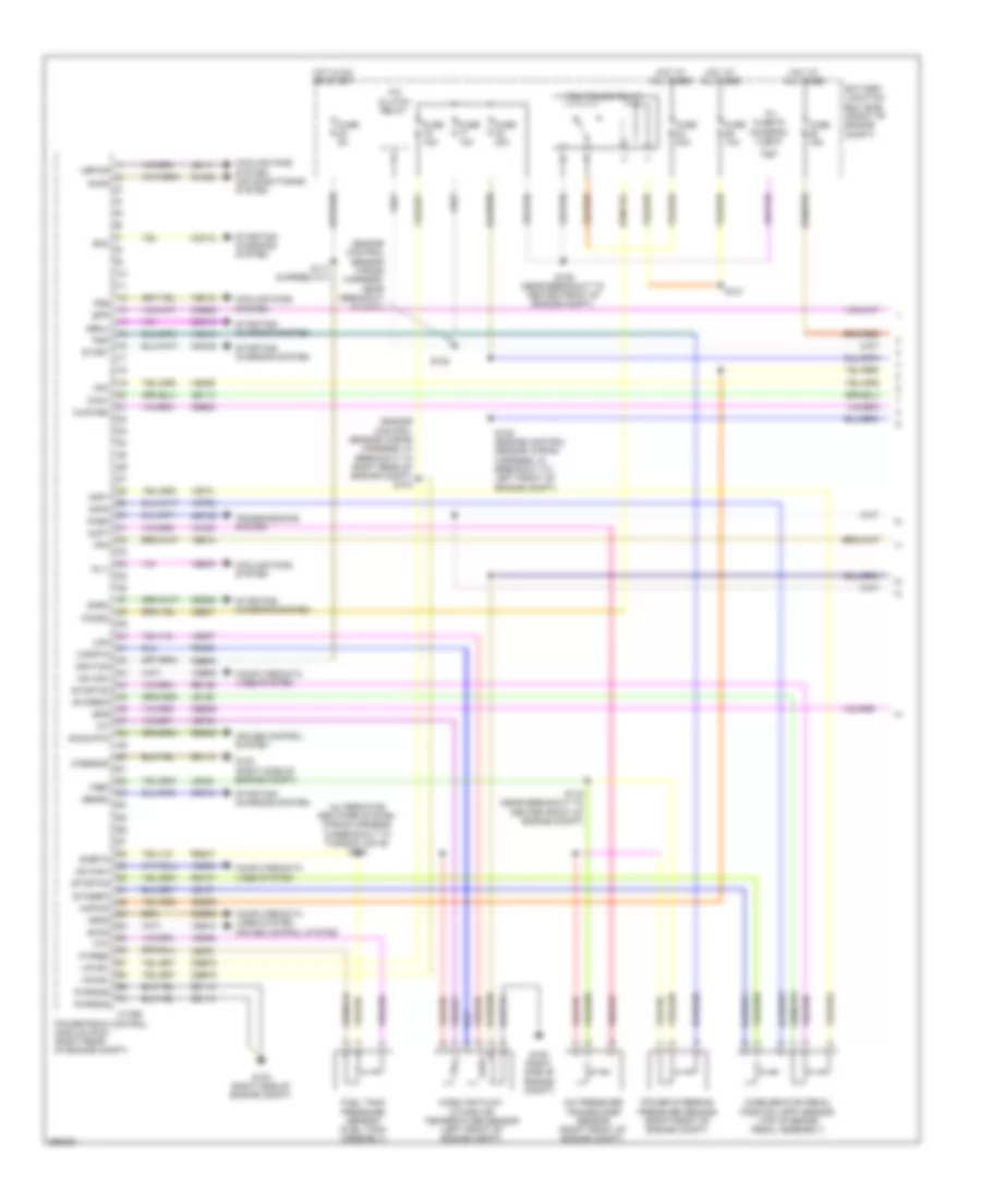
4.6L, Электросхема системы управления двигателем (1 из 5) для Ford Pickup F250 Super Duty 2009


4.6L, Электросхема системы управления двигателем (1 из 5) для Ford Pickup F250 Super Duty 2009 - Список элементов:
- (alternator rectifier system wiring harness, in breakout to fusible link e) s142
- (engine control sensor wiring harness, in breakout to right rear of engine compt)
- (engine control sensor wiring harness, near breakout to g101)
- A/c clutch relay
- A/c pressure transducer sensor (right front of engine compt)
- Accelerator pedal position (app) sensor (top of brake pedal assembly)
- Accr
- Acpt
- App1
- App2
- Battery junction box (bjb) (front of engine compt)
- Bpp
- Bps
- C175b
- Canv
- Casegnd
- Cbb53
- Cbb75
- Ccb08
- Cdb08
- Cdc10
- Cdc12
- Cdc15
- Cdc35
- Ce114
- Ce336
- Ce607
- Ce608
- Ces09
- Ch302
- Computer data lines system
- Computer data lines system cruise control system
- Cooling fans system
- Cooling fans system air conditioning system
- Cruise control system
- Etcref2
- Etcref3
- Etcrtn2
- Etcrtn3
- Fc v
- Feps
- Fpc
- Fpm
- Fss
- Ftp
- Ftpref
- Fuel tank pressure sensor (fuel tank assembly)
- Fuse 10a
- Fuse 15a
- Fuse 20a
- Fuse 40a
- Fuse 5a
- G100 (right side of engine compt)
- Gd113
- Genli
- Genrc
- Hot at all times
- Hot in on or start
- Hs can+
- Hs can-
- Iat
- Ignition
- Injpwrm
- Kapwr
- Le111
- Le136
- Le137
- Le230
- Le424
- Maf
- Mafrtn
- Mass air flow/ intake air temperature sensor (left front of engine compt)
- Pcm power relay
- Pcmrc
- Power steering pressure sensor (right front of engine compt)
- Powertrain control module (pcm) (right rear of engine compt)
- Psp
- Pwrgnd
- Re136
- Re137
- Re320
- Re407
- Res08
- S101
- S103
- S105
- S116 (near breakout to center front of engine compt)
- S125 (near breakout to center front of engine compt)
- S129 (engine control sensor wiring harness, in breakout to left front of engine compt)
- Sbb26
- Sccs
- Sccs rtn
- Sigrtn
- Smc
- Smrc
- Start
- Starting/ charging system
- To fuse 79 (diagram 5 of 5)
- Vbpwr
- Vcs10
- Vdb04
- Vdb05
- Ve203
- Ve225
- Ve518
- Ve701
- Ve702
- Ve740
- Ve807
- Ve922
- Vec10
- Ves10
- Vh433
- Vpwr1
- Vref
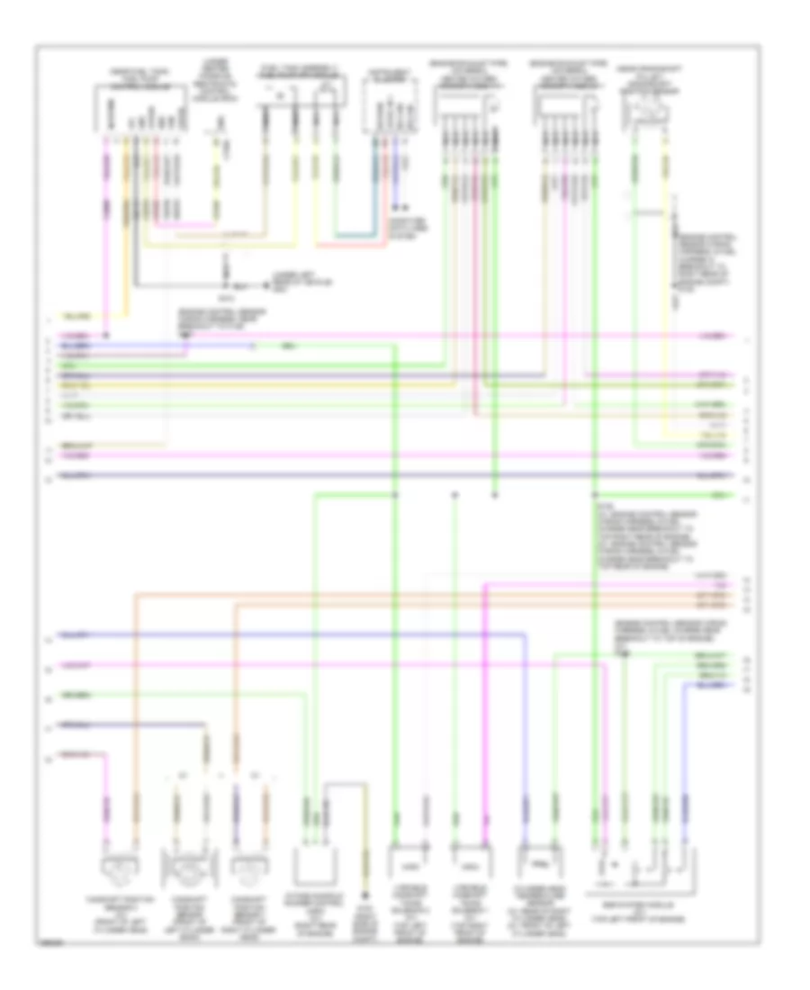
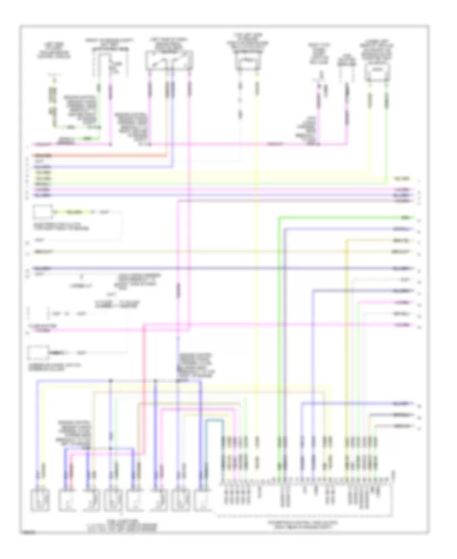
4.6L, Электросхема системы управления двигателем (2 из 5) для Ford Pickup F250 Super Duty 2009
4.6L, Электросхема системы управления двигателем (2 из 5) для Ford Pickup F250 Super Duty 2009 - Список элементов:
- (2v)
- (2v: top of engine) (3v: top front of engine) positive crankcase ventilation (pcv) heated fitting
- (3v)
- (3v: engine control sensor wiring harness, & fuel charge near breakout to top left of engine) (2v: engine control sensor wiring harness, & fuel charge near breakout to top of engine) s134
- (ends in harness)
- (engine control sensor wiring harness, & fuel charge near breakout to top right of engine) (2v) s141
- (engine control sensor wiring harness, near breakout to center front of engine compt) s119
- (engine control sensor wiring harness, near breakout to front center of engine compt) s112
- (front of engine compt) battery junction box (bjb)
- (left side of dash) brake pedal position (bpp) switch
- (left side of dash) trailer brake control module
- (main wiring harness, near breakout to c238) s232
- (or cbb82) boo
- (or cid1)
- (right kick panel) smart junction box (sjb)
- (top front of engine) (2v) heated position crankcase ventilation (pcv) valve
- (under left rear of vehicle) evaporative emission (evap) canister vent solenoid
- 4r75 transmission
- Bpp
- C175e
- C2280b
- Cd8h
- Ce133
- Ce205
- Ce206
- Ce207
- Ce208
- Ce209
- Ce210
- Ce211
- Ce310
- Ce321
- Ce328
- Ce918
- Cht
- Cid2
- Cmp
- Electronic fan clutch (top right front of engine)
- Evr
- Floor shifter (if equipped)
- Fuel inj 1
- Fuel inj 2
- Fuel inj 3
- Fuel inj 4
- Fuel inj 5
- Fuel inj 6
- Fuel inj 7
- Fuel injectors (1, 2, 3 & 4: top right side of engine) (5, 6, 7 & 8: top left side of engine)
- Fuse 10a
- High mounted stoplamp
- Imrc
- Le448
- Le449
- Le450
- Le451
- Le452
- Le453
- Nca
- Overdrive cancel switch (w/ column shifer) (steering column)
- Pcvhc
- Pcvhf
- Powertrain control module (pcm) (right rear of engine compt)
- S222 (4r75 transmission) (main wiring harness, near breakout to right side of dash)
- Uo2sgref11
- Uo2sgref21
- Uo2spc11
- Uo2spc21
- Uo2spct11
- Uo2spct21
- Ve706
- Ve707
- Ve712
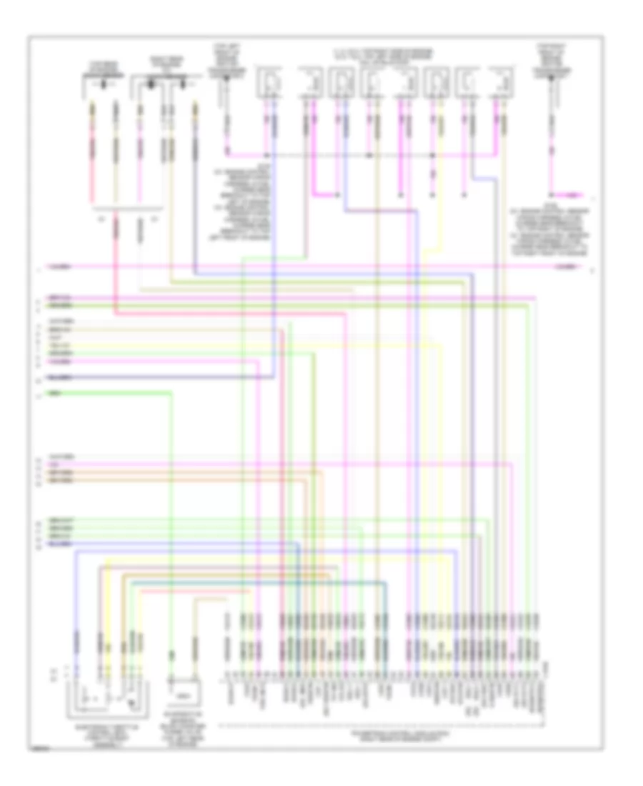
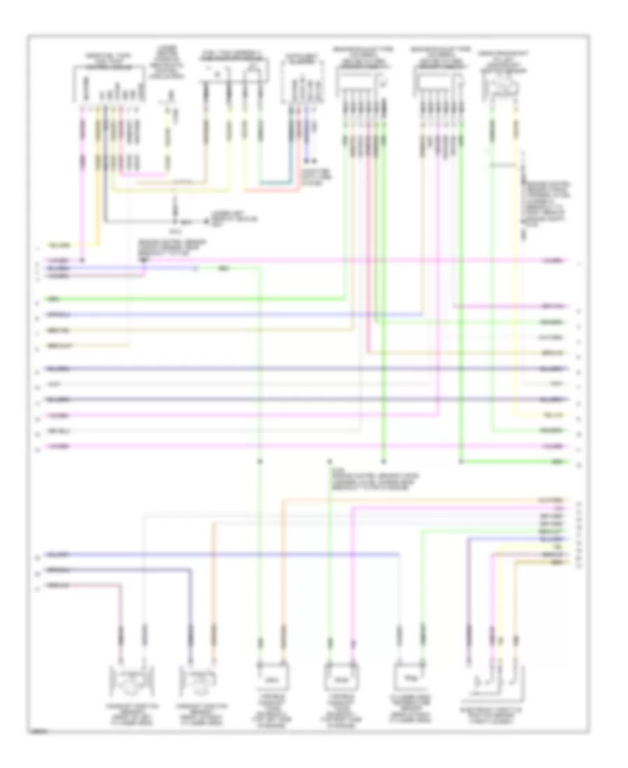
4.6L, Электросхема системы управления двигателем (3 из 5) для Ford Pickup F250 Super Duty 2009
4.6L, Электросхема системы управления двигателем (3 из 5) для Ford Pickup F250 Super Duty 2009 - Список элементов:
- (engine control sensor wiring harness, & fuel charge in breakout to right rear of engine compt) s138
- (engine control sensor wiring harness, & fuel charge near breakout to top of engine) (2v) s140
- (engine control sensor wiring harness, near breakout to c146) s107
- (engine exhaust pipe) universal heated oxygen sensor (ho2s) 11
- (engine exhaust pipe) universal heated oxygen sensor (ho2s) 21
- (fuel tank assembly) fuel pump (fp) module
- (near crankshaft pulley) crankshaft position sensor
- (near fuel tank) fuel pump control module
- (under center console) restraints control module (rcm)
- (under left rear of vehicle) g401
- C310a
- Camshaft position sensor (front of left cylinder bank)
- Camshaft position sensor 1 (front of right cylinder head)
- Camshaft position sensor 2 (3v) (front of left cylinder head)
- Ce515
- Ce606
- Computer data lines system
- Cr167
- Cylinder head temperature sensor (3v: rear of right cylinder head) (2v: front of left cylinder head)
- Egr system module (2v) (top left front of engine)
- Ens
- Fpc
- Fpm
- Fppwr
- Fprtn
- G100 (right side of engine compt)
- Gd117
- Gnd
- Hs can+
- Hs can-
- Injpwrm
- Instrument cluster
- Intake mainfold runner control (imrc) (3v) (right rear
- Level in 1
- Nca
- Of engine)
- Re515
- Return
- S136 (3v: engine control sensor wiring harness, & fuel charge near breakout to top right rear of engine) (2v: engine control sensor wiring harness, & fuel charge near breakout to top rear of engine)
- S412
- Variable camshaft timing solenoid 1 (3v) (top right front of engine)
- Variable camshaft timing solenoid 2 (3v) (top left front of engine)
- Ve518
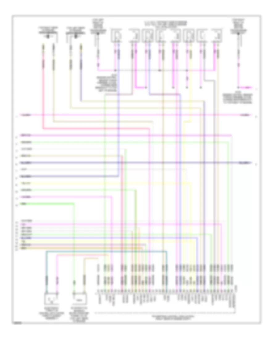
4.6L, Электросхема системы управления двигателем (4 из 5) для Ford Pickup F250 Super Duty 2009
4.6L, Электросхема системы управления двигателем (4 из 5) для Ford Pickup F250 Super Duty 2009 - Список элементов:
- (1, 2, 3 & 4: top right side of engine) (5, 6, 7 & 8: top left side of engine) coil on plug (cop)
- (2v)
- (3v)
- (right rear of engine) (3v) knock sensor
- (top left front of engine) ignition transformer capacitor 2
- (top rear of engine) knock sensor
- (top right front of engine) ignition transformer capacitor 1
- C175e
- Cd1a
- Cd2d
- Cd3b
- Cd4g
- Cd5f
- Cd6e
- Cd7c
- Ce113
- Ce212
- Ce235
- Ce236
- Ce303
- Ce304
- Ce305
- Ce306
- Ce307
- Ce308
- Ce309
- Ce412
- Ce421
- Ce422
- Ce426
- Ckp +
- Ckp -
- De135
- Dpfe
- E sigrtn
- Electronic throttle control (etc) (throttle body assembly)
- Etcref
- Etcrtn
- Evapcp
- Evaporative emission (evap) canister purge valve (top left rear of engine)
- Fuel inj 8
- Ksl1 +
- Ksl1 -
- Ksl2 +
- Ksl2 -
- Le134
- Le423
- Map
- Powertrain control module (pcm) (right rear of engine compt)
- Re134
- Re135
- Re323
- Re324
- Re405
- Re429
- S135 (2v: engine control sensor wiring harness, & fuel charge near breakout to top left of engine) (3v: engine control sensor wiring harness, & fuel charge near breakout to top left front of engine)
- S139 (2v: engine control sensor wiring harness, & fuel charge near breakout to top right of engine) (3v: engine control sensor wiring harness, & fuel charge near breakout to top right front of engine)
- Shdrtn
- Tacm +
- Tacm -
- Tp1 ns
- Tp2 ps
- Uo2s11
- Uo2s21
- Uo2shtr11
- Uo2shtr21
- Vct1
- Vct2
- Ve711
- Ve713
- Ve801
- Ve802
- Ve803
- Ve818
- Ve819
- Ve826
- Ve827
- Vref
- Vrsrtn
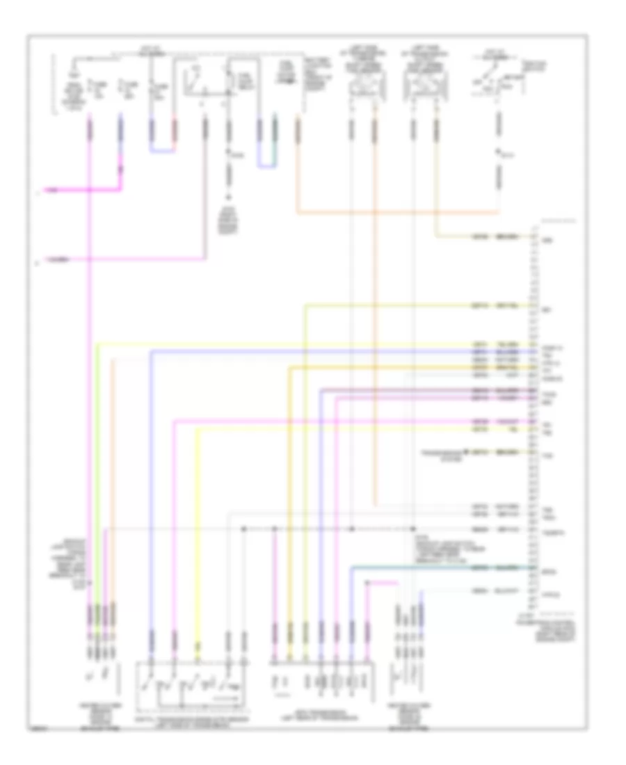
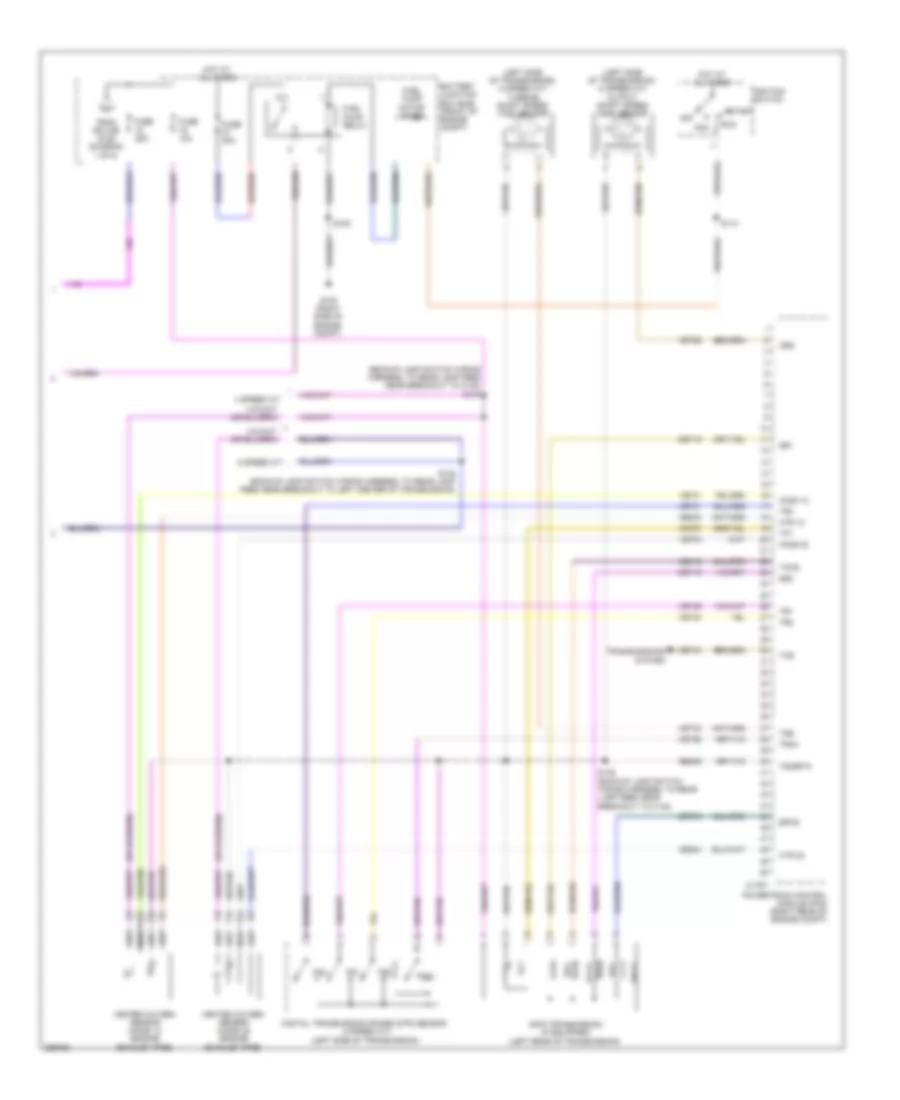
4.6L, Электросхема системы управления двигателем (5 из 5) для Ford Pickup F250 Super Duty 2009
4.6L, Электросхема системы управления двигателем (5 из 5) для Ford Pickup F250 Super Duty 2009 - Список элементов:
- (backup lamp switch wiring harness, to rear lamp feed near breakout to c140) s147
- (left side of transmission) output shaft speed (oss) sensor
- (left side of transmission) turbine shaft speed (tss) sensor
- 4r75 transmission (left rear of transmission)
- Acc
- Battery junction box (front of engine compt)
- C175t
- Ce233
- Ce234
- Ce418
- Cet05
- Cet18
- Cet19
- Cet34
- Digital transmission range (dtr) sensor (left side of transmission)
- Epcs
- From splice s125 (diagram 1 of 5)
- Fuel pump motor diode
- Fuel pump relay
- Fuse 10a
- Fuse 20a
- Fuse 25a
- G100 (right side of engine compt)
- Heated oxygen sensor (ho2s) 12 (engine exhaust pipe)
- Heated oxygen sensor (ho2s) 22 (engine exhaust pipe)
- Ho2s 12
- Ho2s 22
- Hot at all times
- Htr 12
- Htr 22
- Ignition switch
- Off
- Oss
- Powertrain control module (pcm) (right rear of engine compt)
- Re406
- Run
- S106
- S113
- S146 (backup lamp switch wiring harness, to rear lamp feed near breakout to c140)
- Ss1
- Ss2
- Start
- Tccs
- Tcs
- Tft
- Tr1
- Tr2
- Tr3a
- Tr4
- Transmissions system
- Tsigrtn
- Tss
- Ve731
- Ve733
- Vet26
- Vet27
- Vet28
- Vet29
- Vet30
- Vet31
- Vet33
5.4L ГИБКОЕ ТОПЛИВО
5.4L комбинированное топливо, Электросхема системы управления двигателем (1 из 5) для Ford Pickup F250 Super Duty 2009
5.4L комбинированное топливо, Электросхема системы управления двигателем (1 из 5) для Ford Pickup F250 Super Duty 2009 - Список элементов:
- (alternator rectifier system wiring harness, in breakout to fusible link e) s142
- (engine control sensor wiring harness, in breakout to right rear of engine compt) s103
- (engine control sensor wiring harness, near breakout to g101)
- A/c clutch relay
- A/c pressure transducer sensor (right front of engine compt)
- Accelerator pedal position (app) sensor (top of brake pedal assembly)
- Accr
- Acpt
- App1
- App2
- Battery junction box (bjb) (front of engine compt)
- Bpp
- Bps
- C175b
- Canv
- Casegnd
- Cbb53
- Cbb75
- Ccb08
- Cdb08
- Cdc10
- Cdc12
- Cdc15
- Cdc35
- Ce114
- Ce336
- Ce607
- Ce608
- Ces09
- Cet39
- Ch302
- Computer data lines system
- Computer data lines system cruise control system
- Cooling fans system
- Cooling fans system air conditioning system
- Cruise control system
- Etcref2
- Etcref3
- Etcrtn2
- Etcrtn3
- Fc v
- Feps
- Fpc
- Fpm
- Fss
- Ftp
- Ftpref
- Fuel tank pressure sensor (fuel tank assembly)
- Fuse 10a
- Fuse 15a
- Fuse 20a
- Fuse 40a
- Fuse 5a
- G100 (right side of engine compt)
- Gd113
- Genli
- Genrc
- Hot at all times
- Hot in on or start
- Hs can+
- Hs can-
- Iat
- Ignition
- Injpwrm
- Kapwr
- Le111
- Le136
- Le137
- Le230
- Le424
- Maf
- Mafrtn
- Mass air flow/ intake air temperature sensor (left front of engine compt)
- Park
- Pcm power relay
- Pcmrc
- Power steering pressure sensor (right front of engine compt)
- Powertrain control module (pcm) (right rear of engine compt)
- Psp
- Pwrgnd
- Re136
- Re137
- Re320
- Re407
- Res08
- S101
- S105
- S116 (near breakout to center front of engine compt)
- S117 (6 speed a/t)
- S125 (near breakout to center front of engine compt)
- S129 (engine control sensor wiring harness, in breakout to left front of engine compt)
- Sbb26
- Sccs
- Sccs rtn
- Sigrtn
- Smc
- Smrc
- Start
- Starting/ charging system
- To fuse 79 (diagram 5 of 5)
- Transmissions system
- Vbpwr
- Vcs10
- Vdb04
- Vdb05
- Ve203
- Ve225
- Ve518
- Ve701
- Ve702
- Ve740
- Ve807
- Ve922
- Vec10
- Ves10
- Vh433
- Vpwr1
- Vref
5.4L комбинированное топливо, Электросхема системы управления двигателем (2 из 5) для Ford Pickup F250 Super Duty 2009
5.4L комбинированное топливо, Электросхема системы управления двигателем (2 из 5) для Ford Pickup F250 Super Duty 2009 - Список элементов:
- (ends in harness)
- (engine control sensor wiring harness, & fuel charge near breakout to top left of engine) s134
- (engine control sensor wiring harness, near breakout to center front of engine compt) s119
- (engine control sensor wiring harness, near breakout to front center of engine compt) s112
- (front of engine compt) battery junction box (bjb)
- (left side of dash) brake pedal position (bpp) switch
- (left side of dash) trailer brake control module
- (main wiring harness, near breakout to right side of dash) s222
- (or cbb82) boo
- (right kick panel) smart junction box (sjb)
- (top left side of engine) positive crankcase ventilation (pcv) heated fitting
- (under left rear of vehicle) evaporative emission (evap) canister vent solenoid
- 4 speed a/t
- Bpp
- C175e
- C2280b
- Cd8h
- Ce205
- Ce206
- Ce207
- Ce208
- Ce209
- Ce210
- Ce211
- Ce310
- Ce328
- Cht
- Cmp
- Cpm22
- Electronic fan clutch (top right front of engine)
- Floor shifter
- Fuel inj 1
- Fuel inj 2
- Fuel inj 3
- Fuel inj 4
- Fuel inj 5
- Fuel inj 6
- Fuel inj 7
- Fuel injectors (1, 2, 3 & 4: top right side of engine) (5, 6, 7 & 8: top left side of engine)
- Fuse 10a
- High mounted stoplamp
- Le448
- Le449
- Le450
- Le451
- Le452
- Le453
- Main wiring harness, near breakout to c238 s232
- Nca
- Overdrive cancel switch (steering column)
- Pcvhf
- Powertrain control module (pcm) (right rear of engine compt)
- Uo2sgref11
- Uo2sgref21
- Uo2spc11
- Uo2spc21
- Uo2spct11
- Uo2spct21
- Ve706
- Ve707
- Ve712
- W/ column shifter
- W/ floor shifter
5.4L комбинированное топливо, Электросхема системы управления двигателем (3 из 5) для Ford Pickup F250 Super Duty 2009
5.4L комбинированное топливо, Электросхема системы управления двигателем (3 из 5) для Ford Pickup F250 Super Duty 2009 - Список элементов:
- (engine control sensor wiring harness, & fuel charge in breakout to right rear of engine compt) s138
- (engine control sensor wiring harness, near breakout to c146) s107
- (engine exhaust pipe) universal heated oxygen sensor (ho2s) 11
- (engine exhaust pipe) universal heated oxygen sensor (ho2s) 21
- (fuel tank assembly) fuel pump (fp) module
- (near crankshaft pulley) crankshaft position sensor
- (near fuel tank) fuel pump control module
- (under center console) restraints control module (rcm)
- (under left rear of vehicle) g401
- C310a
- Camshaft position sensor 1 (front of right cylinder head)
- Camshaft position sensor 2 (front of left cylinder head)
- Ce515
- Ce606
- Computer data lines system
- Cr167
- Cylinder head temperature sensor (rear of right cylinder head)
- Electronic throttle position sensor (throttle body)
- Ens
- Fpc
- Fpm
- Fppwr
- Fprtn
- Gd117
- Gnd
- Hs can+
- Hs can-
- Injpwrm
- Instrument cluster
- Level in 1
- Nca
- Re515
- Return
- S136 (engine control sensor wiring harness, & fuel charge near breakout to top of engine)
- S412
- Variable camshaft timing solenoid 1 (top right side of engine)
- Variable camshaft timing solenoid 2 (top left side of engine)
- Ve225
- Ve518
5.4L комбинированное топливо, Электросхема системы управления двигателем (4 из 5) для Ford Pickup F250 Super Duty 2009
5.4L комбинированное топливо, Электросхема системы управления двигателем (4 из 5) для Ford Pickup F250 Super Duty 2009 - Список элементов:
- (1, 2, 3 & 4: top right side of engine) (5, 6, 7 & 8: top left side of engine) coil on plug (cop)
- (top left front of engine) ignition transformer capacitor 2
- (top left rear of engine) knock sensor 2
- (top right front of engine) ignition transformer capacitor 1
- (top right rear of engine) knock sensor 1
- C175e
- Cd1a
- Cd2d
- Cd3b
- Cd4g
- Cd5f
- Cd6e
- Cd7c
- Ce113
- Ce212
- Ce235
- Ce236
- Ce303
- Ce304
- Ce305
- Ce306
- Ce307
- Ce308
- Ce309
- Ce412
- Ce421
- Ce422
- Ce426
- Ckp +
- Ckp -
- De135
- E sigrtn
- Electronic throttle control (etc) motor (throttle body assembly)
- Etcref
- Etcrtn
- Evapcp
- Evaporative emission (evap) canister purge valve (top left rear of engine)
- Fuel inj 8
- Ksl1 +
- Ksl1 -
- Ksl2 +
- Ksl2 -
- Le134
- Powertrain control module (pcm) (right rear of engine compt)
- Re134
- Re135
- Re323
- Re324
- Re405
- Re429
- S135 (engine control sensor wiring harness, & fuel charge near breakout to top left of engine)
- S139 (engine control sensor wiring harness, & fuel charge near breakout to top right of engine)
- Shdrtn
- Tacm +
- Tacm -
- Tp1 ns
- Tp2 ps
- Uo2s11
- Uo2s21
- Uo2shtr11
- Uo2shtr21
- Vct1
- Vct2
- Ve711
- Ve801
- Ve802
- Ve818
- Ve819
- Ve826
- Ve827
- Vrsrtn
- Vrsrtn2
5.4L комбинированное топливо, Электросхема системы управления двигателем (5 из 5) для Ford Pickup F250 Super Duty 2009
5.4L комбинированное топливо, Электросхема системы управления двигателем (5 из 5) для Ford Pickup F250 Super Duty 2009 - Список элементов:
- (backup lamp switch wiring harness, to rear lamp feed near breakout to c140) s147
- (left side of transmission) (4 speed a/t) output shaft speed (oss) sensor
- (left side of transmission) (4 speed a/t) turbine shaft speed (tss) sensor
- 4 speed a/t
- 4r75 transmission (if equipped) (left rear of transmission)
- 6 speed a/t
- Acc
- Battery junction box (bjb) (front of engine compt)
- C175t
- Ce233
- Ce234
- Ce418
- Cet05
- Cet18
- Cet19
- Cet34
- Digital transmission range (dtr) sensor (4 speed a/t) (left side of transmission)
- Epcs
- From splice s125 (diagram 1 of 5)
- Fuel pump motor diode
- Fuel pump relay
- Fuse 10a
- Fuse 20a
- Fuse 25a
- G100 (right side of engine compt)
- Heated oxygen sensor (ho2s) 12 (engine exhaust pipe)
- Heated oxygen sensor (ho2s) 22 (engine exhaust pipe)
- Ho2s 12
- Ho2s 22
- Hot at all times
- Htr 12
- Htr 22
- Ignition switch
- Off
- Oss
- Powertrain control module (pcm) (right rear of engine compt)
- Re406
- Run
- S106
- S113
- S146 (backup lamp switch wiring harness, to rear lamp feed near breakout to c140)
- S148 (backup lamp switch wiring harness, to rear lamp feed near breakout to left center of transmission)
- Ss1
- Ss2
- Start
- Tccs
- Tcs
- Tft
- Tr1
- Tr2
- Tr3a
- Tr4
- Transmissions system
- Tsigrtn
- Tss
- Ve731
- Ve733
- Vet26
- Vet27
- Vet28
- Vet29
- Vet30
- Vet31
- Vet33

 Čeština
 Dansk
Dansk Deutsch
 Ελληνικά
 English
 English
 Español
 Suomi
Suomi Français
 Français
 עברית
עברית Hrvatski
 Magyar
 日本語
日本語 한국어
한국어 Nederlands
 Polski
 Português
 Português
 Română
 Русский
 Slovenčina
 Slovenščina
 Svenska
 Türkçe
 中文 (中国)