POWER DISTRIBUTION
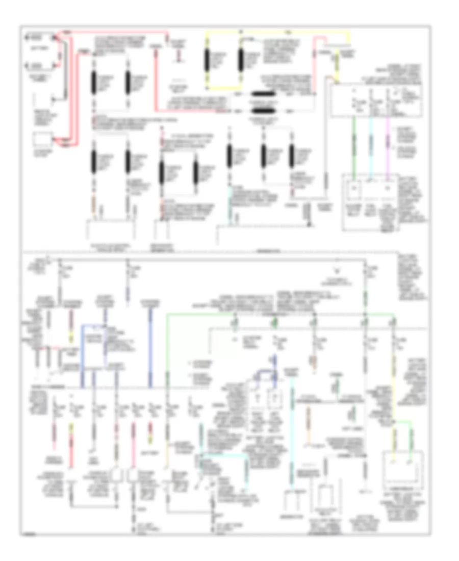
Power Distribution Wiring Diagram (1 of 4) for Ford Econoline E150 2004
List of elements for Power Distribution Wiring Diagram (1 of 4) for Ford Econoline E150 2004:
- (at front of center console)
- (at left kick panel) g204
- (at left side of dash) g202
- (at right rear of engine compt)
- (diesel)
- (diesel: at right rear of engine compt) (except diesel: at left side of engine compt)
- (diesel: at right rear of engine compt) (except diesel: at left side of engine compt) battery junction box (bjb)
- (diesel: near breakout to trailer tow right turn relay) (diesel: near breakout to trailer tow right turn relay) (except diesel: near breakout to g105) (except diesel: near breakout to g105) (except stripped chassis) s1028
- (except diesel: near breakout to g105) (diesel: near breakout to c237) s2012
- (except diesel: near breakout to g105) (diesel: near breakout to starter relay) s1034
- (in alternator rectifier system wiring harness, near breakout to right side of engine) s1071
- (in alternator rectifier system wiring harness, near breakout to top left rear of engine) s1076
- (in engine control sensor harness, near breakout to g107) s145
- (in starter relay to fuse junction panel harness, in breakout to right side of engine compt)
- (in starter relay/battery wiring harness, in breakout to left side of engine compt) s1074
- (in window regulator relay switch harness, near breakout to steering column)
- (near breakout to c1101)
- (near breakout to c1101) s1054
- (near breakout to top left rear of engine) red s1073
- (not used)
- (stripped chassis) s1031
- 4.6l & 5.4l
- A/c clutch relay
- Auxiliary relay
- Auxiliary relay box 1 (except stripped chassis) (diesel: at right rear of engine compt) (except diesel: at left rear of engine compt)
- Battery
- Battery feed
- Battery ii (diesel)
- Battery junction box (bjb)
- Battery junction box (bjb) (diesel: at right rear of engine compt) (except diesel: at left side of engine compt)
- Battery junction box (bjb) (stripped chassis) (diesel: at right rear of engine compt) (except diesel: at left side of engine compt)
- Blower motor relay
- Box 1
- C102a
- C1251a
- C1301a
- C1301b
- Central junction box (cjb) (behind left side of dash)
- Chassis
- Chassis)
- Console 1 power point (w/ rse)
- Console 2 power point (w/ rse) (at front of center console)
- Cutaway
- Data link connector (dlc)
- Daytime running lamps (drl) module (if equipped)
- Diesel
- Ends in harness
- Except
- Except 4.6l & 5.4l stripped chassis
- Except cutaway
- Except diesel
- Except stripped chassis
- From a fuse 19 (diagram 1 of 4)
- Front cigar lighter (except stripped chassis)
- Fuel injector control module (ficm) power relay
- Fuel pump relay
- Fuse 10a
- Fuse 15a
- Fuse 20a
- Fuse 20a 30a
- Fuse 30a
- Fuse 50a
- Fuse 50a (diesel)
- Fuse 60a
- Generator
- Glow plug control module (gpcm)
- Horn relay
- Left turn trailer tow relay
- Modified vehicle
- Nca
- Power point (behind left "b" pillar)
- Power point (except cutaway) (behind left "b" pillar)
- Red
- Remote jump start terminal (diesel)
- Right turn trailer tow relay
- S1008
- S1019
- S1055
- S1056 (in engine control sensor & fuel charge wiring harness, near breakout to c1101)
- S1072 (in alternator rectifier system wiring harness, near breakout to right side of engine)
- S1075 (in alternator rectifier system wiring harness, near breakout to top left rear of engine)
- S207
- S235
- S266 (w/o rse: near breakout to to central junction box)
- Secondary generator
- Starter motor
- Starter relay
- Starter relay (diesel)
- Stripped
- Stripped chassis
- To fuse 21 (diagram 2 of 4)
- To fuse 9 (diagram 1 of 4)
- W/ dual generators
- W/ single generators
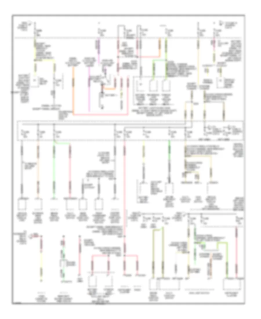
Power Distribution Wiring Diagram (2 of 4) for Ford Econoline E150 2004
List of elements for Power Distribution Wiring Diagram (2 of 4) for Ford Econoline E150 2004:
- (behind left side of dash) central junction box (cjb)
- (diesel)
- (except diesel)
- (except diesel: near breakout to g105)
- (except diesel: near breakout to g105) (diesel: near breakout to starter relay) s1033
- (except diesel: near breakout to right side of dash) (diesel: near breakout to left side of dash) s291
- (in main wiring harness, in breakout to c219)
- (in main wiring harness, near breakout to center of dash) s205
- (in main wiring harness, near breakout to left side of dash) s219
- (in main wiring harness, near breakout to left side of dash) s221
- (in main wiring harness, under left side of dash) s276
- (in window regulator relay switch harness, near breakout to c248) s237
- (in window regulator relay switch harness, near breakout to right side of dash) (w/ remote keyless entry) s261
- (not used)
- Auxiliary battery relay
- Auxiliary relay box 2 (behind center of dash)
- Battery charge trailer tow relay
- Battery ii
- Battery junction box (bjb) (diesel: at right rear of engine compt) (except diesel: at left side of engine compt)
- Battery saver relay
- Brake pedal position switch
- C175
- C176a
- C202a batt
- C202b
- C203a
- C2188a
- C220a
- C220b
- C3077a
- Central junction box (cjb) (behind left side of dash)
- Courtesy sw feed
- Cutaway
- Diesel and all w/o auxiliary battery
- Driver side front seat adjust switch
- Ends in harness
- Except cutaway
- Except modified vehicles
- Except stripped chassis
- Exterior rear view mirror switch
- From b fuse 18 (diagram 1 of 4)
- From fuse 4 (diagram 2 of 4)
- From fuse 5 (diagram 2 of 4)
- Front passenger window/ door lock switch
- Fuse
- Fuse (except diesel)
- Fuse 10a
- Fuse 15a
- Fuse 20a
- Fuse 30a
- Fuse 40a
- Fuse 50a
- Fuse 5a
- Fuse 60a
- Fuse fuse 30a 30a
- Gasoline w/ auxiliary battery
- Gasoline w/ auxiliary battery jumper
- Instrument cluster
- Interior lamp relay
- Main light switch
- Master window/ door lock/ unlock switch
- Multi- function switch
- Nca
- Parking lamp trailer tow relay
- Pcm power relay
- Power choke 1
- Powertrain control module (pcm)
- Radio
- Rear a/c blower speed relay 1
- Rear doors door lock switch
- Rear seat entertainment (rse) module
- Red
- Reversing lamp trailer tow relay
- S1027 (diesel: near breakout to starter relay)
- S1032 (diesel: in engine control sensor wiring harness, near breakout to starter relay) (except diesel: near breakout to g105)
- S218
- S225
- Stripped chassis
- To accessory delay relay (diagram 3 of 4)
- To fuse 10 (diagram 2 of 4)
- To fuse 15 (diagram 3 of 4)
- To fuse 17 (diagram 2 of 4)
- Vehicle security module (vsm)
- Vehicle security module (vsm) (w/ remote keyless entry)
- Video cassette player
- W/ auxiliary a/c
- W/ power locks, w/o remote keyless entry
- W/ remote keyless entry
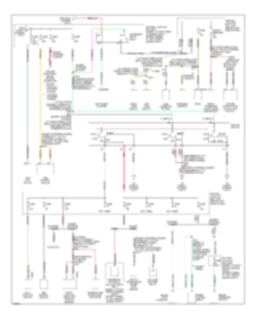
Power Distribution Wiring Diagram (3 of 4) for Ford Econoline E150 2004
List of elements for Power Distribution Wiring Diagram (3 of 4) for Ford Econoline E150 2004:
- (except stripped chassis: in breakout to c110) (stripped chassis: in breakout to left side of engine compt) s177
- (in interior lamps wiring harness, near breakout to c925)
- (in main wiring harness, in breakout to steering column) (stripped chassis) s280
- (in window regulator relay switch harness, near breakout to c237) s245
- (in window regulator relay switch harness, near breakout to right side of dash) s242
- (in window regulator relay switch harness, near breakout to steering column)
- (in window regulator relay switch harness, under left side of dash) s236
- (near breakout in top of driver door) s501
- (near breakout to left side of dash) (stripped chassis) s281 s271 (except stripped chassis) (near breakout to steering column)
- (not used)
- (w/ auxiliary battery) s113
- 4.6l & 5.4l stripped chassis
- A/c switch
- Abs control module
- Acc
- Accessory delay relay
- Auxiliary battery relay
- Battery junction box (bjb) (diesel: at right rear of engine compt) (except diesel: at left side of engine compt)
- Brake pressure switch
- Brake shift interlock
- C202a
- C2188a
- C220b
- C294a
- Central junction box (cjb) (behind left side of dash)
- Circuit breaker 20a
- Diesel
- Digital transmission range (dtr) sensor
- Except
- Except diesel
- Except stripped chassis
- From e fuse 14 (diagram 2 of 4)
- From s291 f (diagram 2 of 4)
- Front function selector switch assembly
- Front passenger window/door lock switch
- Fuse
- Fuse 10a
- Fuse 15a
- Fuse 2a
- Fuse 30a
- Fuse 30a 40a
- Fuse 5a
- Fuse 60a
- Ign
- Ignition switch
- Instrument cluster
- Left video display
- Lock
- Main light switch
- Master window/door lock/unlock switch
- Multi- function switch
- Off
- Overhead console
- Pnk/
- Radio
- Red
- Reversing lamp relay auxiliary relay box 1 (diesel: at right rear of engine compt) (except diesel: at left rear of engine compt)
- Right video display
- Run
- S124 (diesel: in breakout to c237) (except diesel: near breakout to left side of engine compt)
- S203
- S227
- S230 (except stripped chassis) (in window regulator relay switch harness, near breakout to steering column)
- S914
- Speed control servo
- Start
- Stripped chassis
- Temperature blend door actuator
- To fuse 14 (diagram 4 of 4)
- To fuse 33 (diagram 4 of 4)
- To fuse 9 (diagram 4 of 4)
- Trailer electronic brake control connector
- Video cassette player
- W/ overhead console
- W/ power door locks
- W/ rse
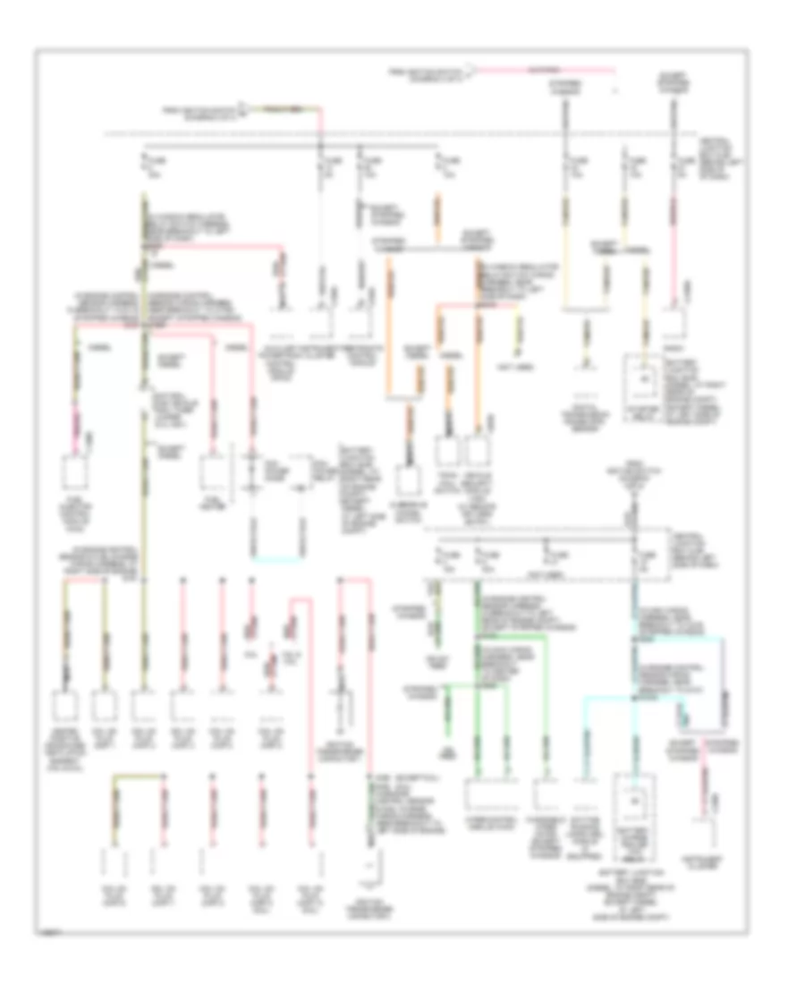
Power Distribution Wiring Diagram (4 of 4) for Ford Econoline E150 2004
List of elements for Power Distribution Wiring Diagram (4 of 4) for Ford Econoline E150 2004:
- (6.8l)
- (except 6.8l)
- (in engine control (in engine control sensor harness, in breakout to g112) (stripped chassis) s127
- (in engine control sensor & fuel charge wiring harness, at right side of engine) s161
- (in engine control sensor harness, in breakout to left rear of engine compt) (except stripped chassis) s128
- (in engine control sensor wiring harness, near breakout to g107) s1022
- (in main wiring harness, near breakout to c219) (stripped chassis) s282
- (in main wiring harness, near breakout to center of dash) s208
- (in window regulator relay switch harness, near breakout to left side of dash) s246
- (not used)
- (w/ remote keyless entry)
- 4.6l & 5.8l
- 6.8l
- Auxiliary powertrain control module (apcm)
- Battery charge trailer tow relay
- Battery junction box (bjb) (diesel: at right rear of engine compt) (except diesel: at left side of engine compt)
- C1388c
- C203b
- C2188a
- C220a
- C220b
- C310a
- Cancel switch
- Central junction box (cjb) (behind left side of dash)
- Central junction box (cjb) (behind left side of of dash)
- Coil on plug (cop) 1
- Coil on plug (cop) 10 (6.8l)
- Coil on plug (cop) 2
- Coil on plug (cop) 3
- Coil on plug (cop) 4
- Coil on plug (cop) 5
- Coil on plug (cop) 6
- Coil on plug (cop) 7
- Coil on plug (cop) 8
- Coil on plug (cop) 9 (6.8l)
- Daytime running lamps (drl) module (if equipped)
- Diesel
- Digital transmission range (dtr) sensor
- Except diesel
- Except stripped chassis
- From ignition switch (diagram 3 of 4)
- From ignition switch k (diagram 3 of 4)
- From ignition switch l (diagram 3 of 4)
- Fuel heater
- Fuel injector control module (ficm)
- Fuse
- Fuse 10a
- Fuse 15a
- Fuse 30a
- Fuse 5a
- Haul switch
- Heated positive crankcase ventilation element (4.6l & 6.8l)
- Ign feed
- Ign sw feed
- Ignition transformer capacitor 1
- Ignition transformer capacitor 2
- Instrument cluster
- Natural gas vehicle (ngv) timer jumper (5.4l ngv)
- Nca
- Overdrive
- Pcm power diode
- Pcm power relay
- Radio
- Restraints control module
- S156
- S162 (in engine control sensor & fuel charge wiring harness, near breakout to left side of engine)
- Security module (vsm)
- Sensor wiring harness, near breakout to c1760) (except stripped chassis) s1065
- Starter relay
- Stripped chassis
- Tan/red
- Town/
- Vehicle
- Windshield wiper motor (except stripped chassis)
- Wiper control module (wcm)

 Čeština
 Dansk
Dansk Deutsch
 Ελληνικά
 English
 English
 Español
 Suomi
Suomi Français
 Français
 עברית
עברית Hrvatski
 Magyar
 日本語
日本語 한국어
한국어 Nederlands
 Polski
 Português
 Português
 Română
 Русский
 Slovenčina
 Slovenščina
 Svenska
 Türkçe
 中文 (中国)