Čeština
 Dansk
Dansk Deutsch
 Ελληνικά
 English
 English
 Español
 Suomi
Suomi Français
 Français
 עברית
עברית Hrvatski
 Magyar
 日本語
日本語 한국어
한국어 Nederlands
 Polski
 Português
 Português
 Română
 Русский
 Slovenčina
 Slovenščina
 Svenska
 Türkçe
 中文 (中国)

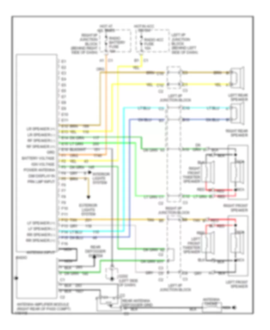
RADIO
Radio Wiring Diagrams, with Amplifier for Oldsmobile Alero GX 1999
List of elements for Radio Wiring Diagrams, with Amplifier for Oldsmobile Alero GX 1999:
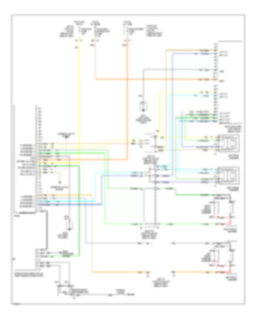

Radio Wiring Diagrams, without Amplifier for Oldsmobile Alero GX 1999
List of elements for Radio Wiring Diagrams, without Amplifier for Oldsmobile Alero GX 1999: