
 Čeština
 Dansk
Dansk Deutsch
 Ελληνικά
 English
 English
 Español
 Suomi
Suomi Français
 Français
 עברית
עברית Hrvatski
 Magyar
 日本語
日本語 한국어
한국어 Nederlands
 Polski
 Português
 Português
 Română
 Русский
 Slovenčina
 Slovenščina
 Svenska
 Türkçe
 中文 (中国)

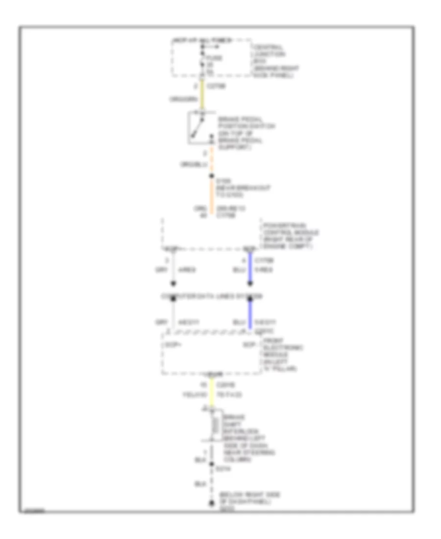
SHIFT INTERLOCK
Shift Interlock Wiring Diagram for Ford Thunderbird 2005
List of elements for Shift Interlock Wiring Diagram for Ford Thunderbird 2005:

ANTI-LOCK BRAKESCOMPUTER DATA LINESANTI-THEFTBODY CONTROL MODULESAIR CONDITIONINGDEFOGGERSEXTERIOR LIGHTSELECTRONIC POWER STEERINGHORNENGINE PERFORMANCEINSTRUMENT CLUSTERGROUND DISTRIBUTIONCOOLING FANCRUISE CONTROLINTERIOR LIGHTSHEADLIGHTSPOWER SEATSPOWER DOOR LOCKSPOWER DISTRIBUTIONSHIFT INTERLOCKRADIOSTARTING/CHARGINGPOWER TOP/SUNROOFPOWER MIRRORSSUPPLEMENTAL RESTRAINTSPOWER WINDOWSWARNING SYSTEMSTRUNK, TAILGATE, FUEL DOORTRANSMISSIONWIPER/WASHER