SUPPLEMENTAL RESTRAINTS
Supplemental Restraint Wiring Diagram for Ford Expedition 1999
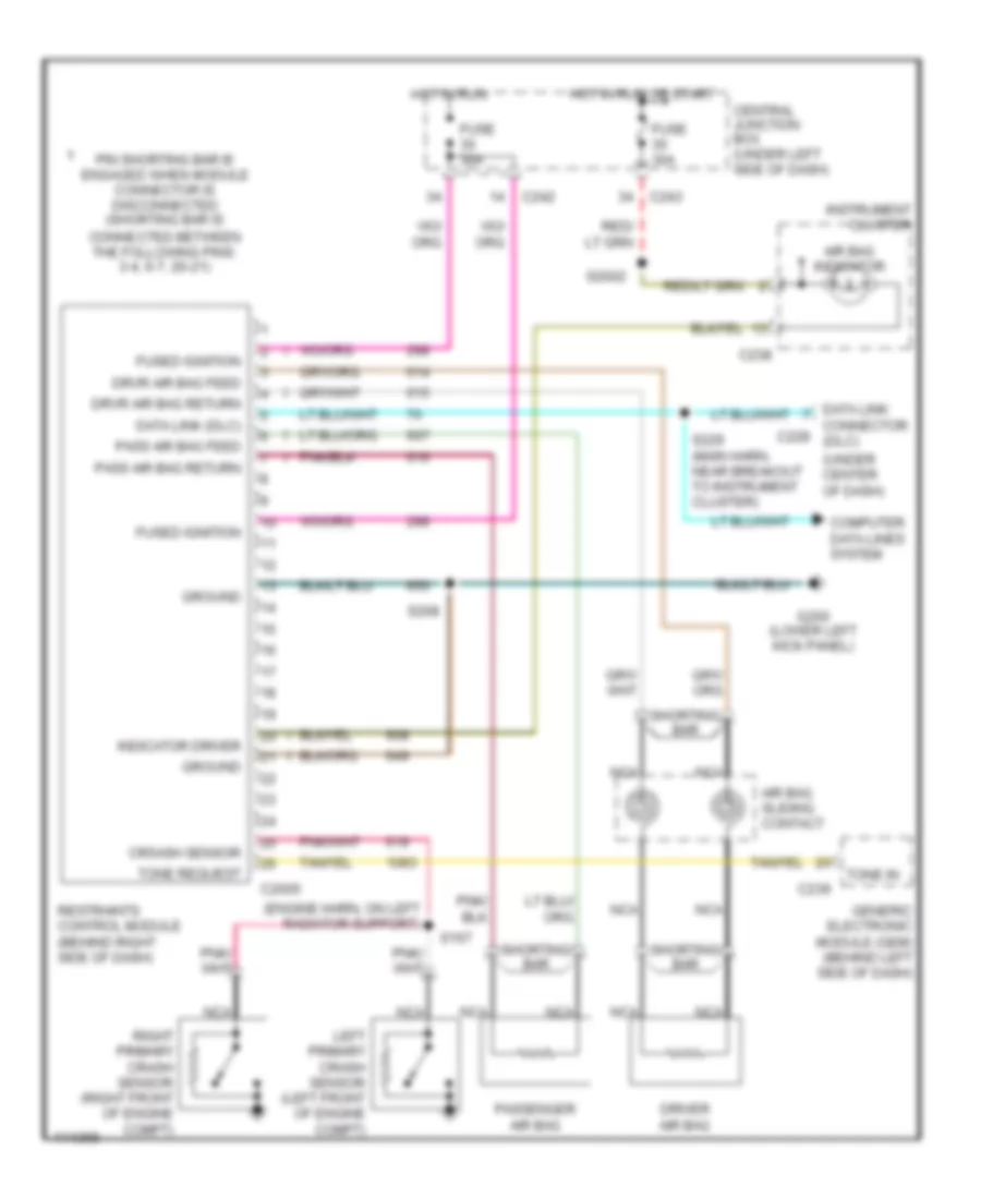
List of elements for Supplemental Restraint Wiring Diagram for Ford Expedition 1999:
- (engine harn, on left radiator support)
- (under center of dash)
- Air bag indicator
- Air bag sliding contact
- C2005
- C228
- C238
- C239
- C242
- C243
- Central junction box (under left side of dash)
- Computer data lines system
- Connector (dlc)
- Cr5ash sensor
- Data link
- Data link (dlc)
- Driver air bag
- Drvr air bag feed
- Drvr air bag return
- Fuse 30a
- Fused ignition
- G200 (lower left kick panel)
- Generic electronic module (gem) (behind left side of dash)
- Ground
- Hot in run
- Hot in run or start
- Indicator driver
- Instrument cluster
- Left primary crash sensor (left front of engine compt)
- Nca
- Pass air bag feed
- Pass air bag return
- Passenger air bag
- Pin shorting bar is engaged when module connector is disconnected (shorting bar is connected between the following pins: 3-4, 6-7, 20-21)
- Restraints control module (behind right side of dash)
- Right primary crash sensor (right front of engine compt)
- S157
- S2002
- S208
- S229 (main harn, near breakout to instrument cluster)
- Shorting bar
- Tone in
- Tone request
 Čeština
 Dansk
Dansk Deutsch
 Ελληνικά
 English
 English
 Español
 Suomi
Suomi Français
 Français
 עברית
עברית Hrvatski
 Magyar
 日本語
日本語 한국어
한국어 Nederlands
 Polski
 Português
 Português
 Română
 Русский
 Slovenčina
 Slovenščina
 Svenska
 Türkçe
 中文 (中国)
 Italiano