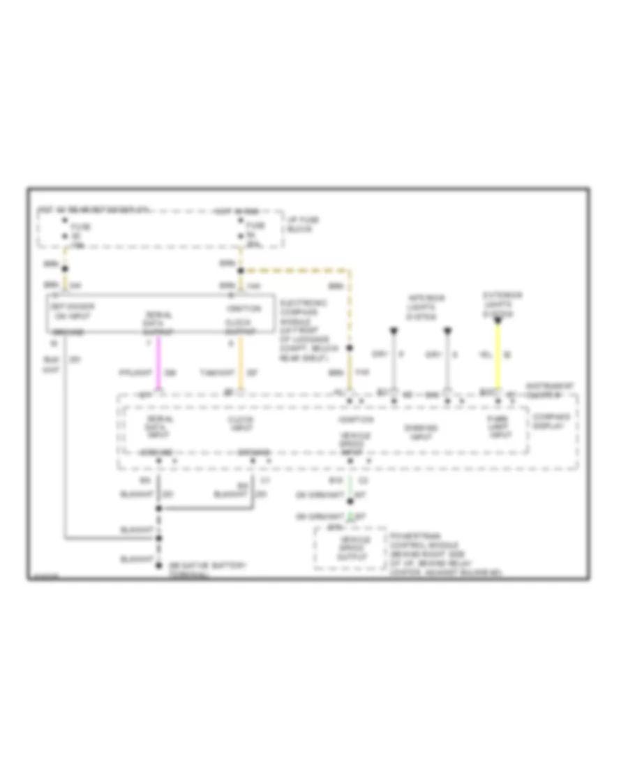
INSTRUMENT CLUSTER
Electronic Compass Wiring Diagram for Pontiac Bonneville SSEi 1994
List of elements for Electronic Compass Wiring Diagram for Pontiac Bonneville SSEi 1994:
- B10
- B12
- B16
- Clock input
- Clock output
- Compass display
- D15
- Defogger on input
- Dimming input
- Electronic compass module (lh front of luggage compt, below rear shelf)
- Exterior lights system
- Fuse 3d 10a
- Fuse 5a 10a
- Ground
- Hot in run
- Hot w/ rear defogger on
- I/p fuse block
- Ignition
- Instrument cluster
- Interior lights system
- Park lamp input
- Powertrain control module (behind right side of i/p, behind relay center, against bulkhead)
- Serial data input
- Serial data output
- Vehicle speed input
- Vehicle speed output
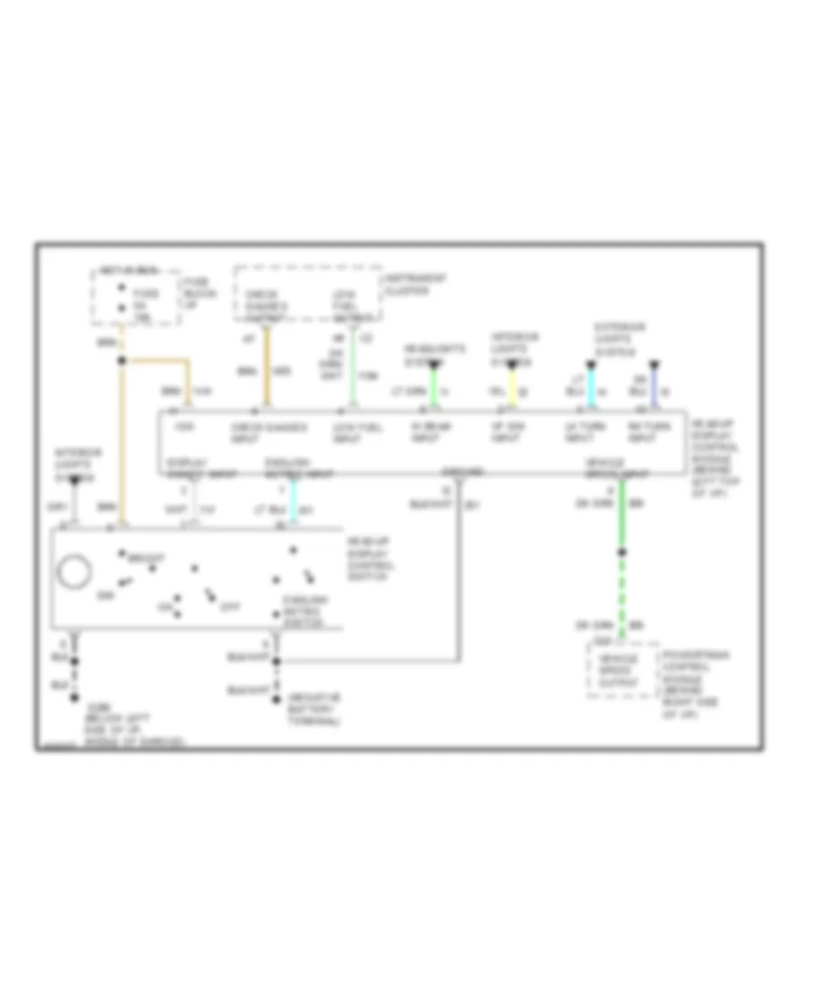
Head-Up Display Wiring Diagram for Pontiac Bonneville SSEi 1994
List of elements for Head-Up Display Wiring Diagram for Pontiac Bonneville SSEi 1994:
-
- Bright
- Check gauges input
- Check gauges output
- D15
- Dim
- Display on/off input
- English/ metric input
- English/ metric switch
- Exterior lights system
- Fuse 5a 10a
- Fuse block: i/p
- G200 (below left side of i/p, middle of shroud)
- Ground
- Head-up display control module (behind left top of i/p)
- Head-up display control switch
- Headlights system
- Hi beam input
- Hot in run
- Ign
- Instrument cluster
- Interior lights system
- Lh turn input
- Low fuel input
- Low fuel output
- Off
- Powertrain control module (behind right side of i/p)
- Rh turn input
- Vehicle speed input
- Vehicle speed output
- Vf dim input
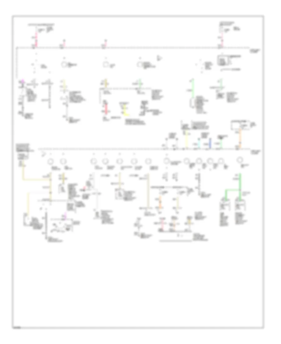
Instrument Cluster Wiring Diagram, Base for Pontiac Bonneville SSEi 1994
List of elements for Instrument Cluster Wiring Diagram, Base for Pontiac Bonneville SSEi 1994:
- (left front of engine compt)
- (not used)
- (top left side of engine)
- A12
- A13
- A16
- Abs ind. ctrl
- Acc
- Anti- lock diode
- Anti- lock ind.
- Antilock brakes system
- B1 volts ind. ctrl
- B10
- B10 ect ind. ctrl
- B11
- B12
- B16
- B17
- Brake fluid level switch
- Brake indicator
- Brake warning input
- Change oil ind.
- Check oil level ind.
- D13
- D15
- Diagnostic energy reserve module (behind i/p, right of accelerator pedal)
- Ects input
- Electronic brake control module (attached to left front strut tower)
- Engine controls system
- Engine coolant
- Engine coolant temp. gauge
- Engine coolant temperature ind.
- Engine coolant temperature sender (top left side of engine) (hot-55 ) (cold-1365 )
- Exterior lights system
- Fasten belts ind.
- Fasten belts ind. ctrl
- Fuel gauge
- Fuel gauge sender (on top of fuel tank) (full-90 ) (empty-0 )
- Fuse 1d 15a
- Fuse 5a 10a
- Fuse 8 10a
- Fuse 9c 10a
- Fuse block: i/p
- G100
- G200 (below left side of i/p)
- G203 (below right side of i/p)
- Gen input
- Gen output
- Generator
- Gnd
- Headlights system
- Hi beam ind.
- Hot at all times
- Hot in run
- Hot in run, bulb test or start
- Ignition switch
- Illumination (9 bulbs)
- Infl. rest. ind.
- Instrument cluster
- Interior lights system
- Left turn ind.
- Lock
- Low oil level output
- Low oil level sensor (lower left front of engine)
- Malfunction ind.
- Master cylinder reservoir
- Mil ind. ctrl
- Multi-function chime module (behind i/p, right of steering column)
- Nca
- Odometer
- Off
- Oil level module (behind right side of i/p)
- Oil pressure ind.
- Oil pressure switch (lower right rear of engine) (open with normal oil pressure )
- Park brake switch (opens with park brake released)
- Pass- key ii decoder module (behind top right side of i/p)
- Pnk
- Pnk a15
- Pnk a6
- Pnk b2
- Pnk b4
- Power
- Powertrain control module (behind right side of i/p)
- Red
- Relay center
- Remote accessory control module (behind right side of i/p)
- Right turn ind.
- Run
- Security ind.
- Security ind. ctrl
- Sensor return
- Signal output
- Sir ind. ctrl
- Solid state driver/ logic
- Speedometer
- Start bulb test
- Tan
- Temperature sensor
- Traction off ind.
- Vehicle speed output
- Volts ind.
- With ua6 only
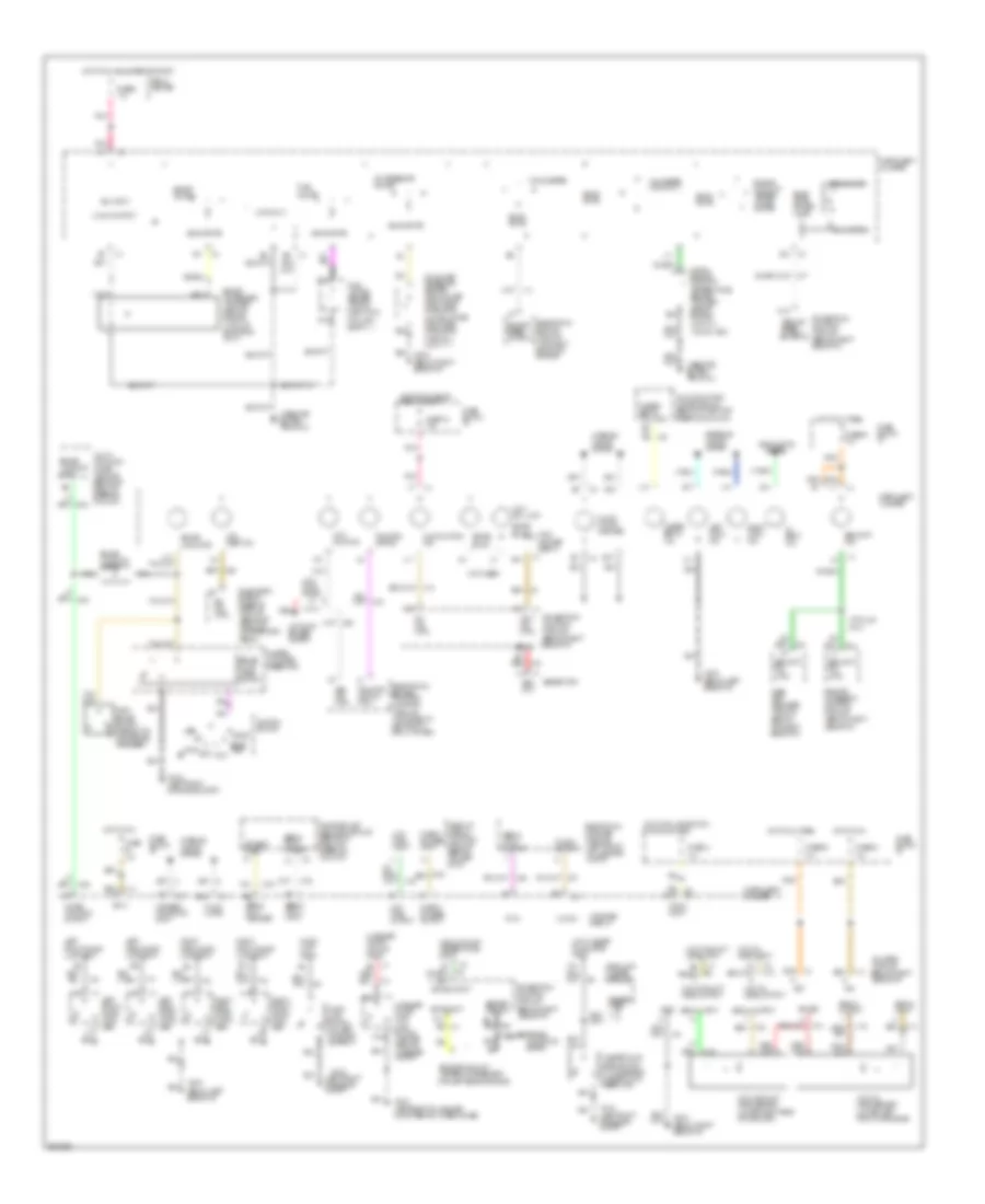
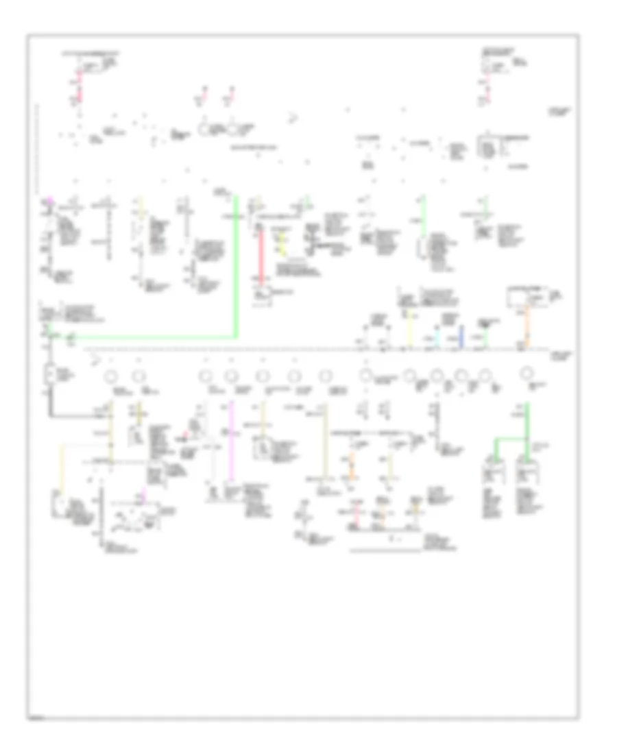
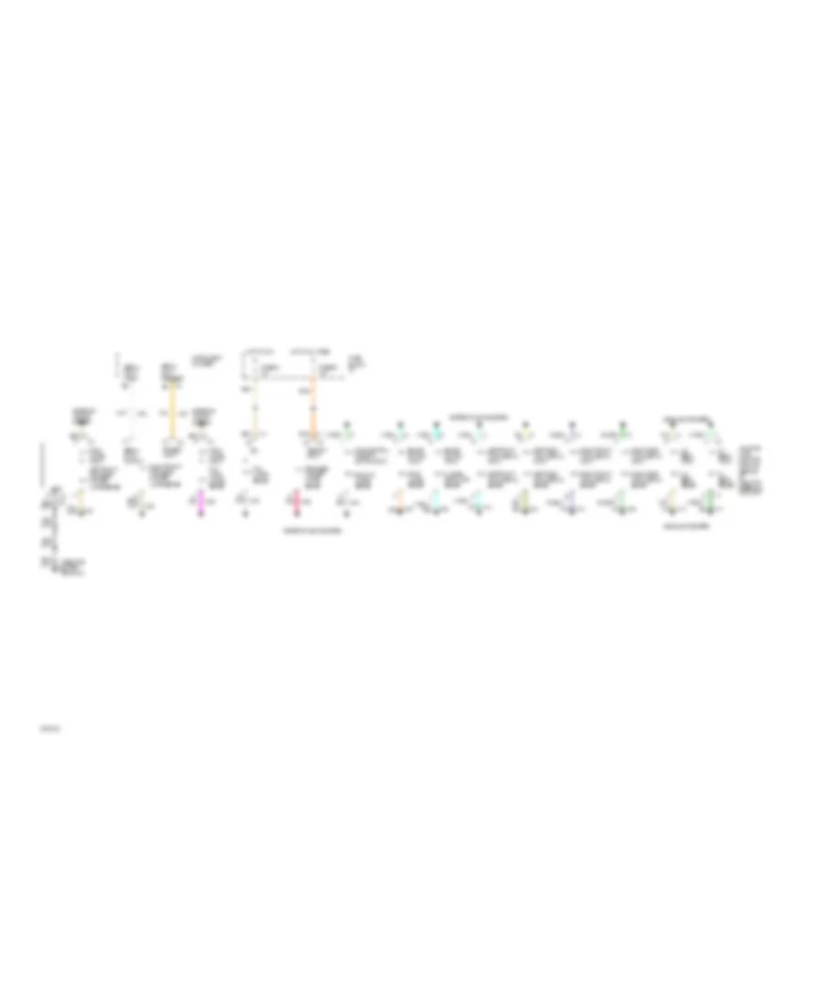
Instrument Cluster Wiring Diagram, Gauges, U2F & U50 for Pontiac Bonneville SSEi 1994
List of elements for Instrument Cluster Wiring Diagram, Gauges, U2F & U50 for Pontiac Bonneville SSEi 1994:
- (left front of engine compt)
- (not used)
- (top left side of engine)
- (u2f only)
- (u2f)
- (u50) voltage level in
- 5 volt output
- A11
- A12
- A13
- A15
- A16
- Abs ind. ctrl
- Acc
- Adaptive lamp monitor module (behind i/p, right of steering column)
- Anti- lock diode
- Anti- lock ind.
- Antilock brakes system
- B1 volt ind. ctrl
- B10
- B11
- B12
- B13
- B14
- B15
- B16
- B17
- B4 red l
- B6 serial data request
- Boost gauge
- Boost/ map sensor (top left rear of engine) (with l67 sc engine only)
- Brake fluid level switch
- Brake indicator
- Brake warning diode
- Brake warning input
- Check gauges input
- Check gauges output
- Chime control output
- Clock
- Clock output
- Compass display
- D13
- D15
- Data
- Diagnostic energy reserve module (behind i/p, right of accelerator pedal)
- Digital engine coolant temperature sender (top left side of engine) (hot-40 ) (cold-1365 )
- Ects input
- Ects output
- Electronic brake & traction control module (attached to left front strut tower)
- Electronic compass module (left front of luggage compt)
- Electronic ignition module (top right front of engine)
- Enable input a2
- Engine controls system
- Engine coolant
- Engine coolant temper- ature gauge
- Engine speed output
- Exterior lights system
- Fasten belts ind.
- Fasten belts ind. ctrl
- Fuel gauge
- Fuel gauge sender (top of fuel tank) (full-88 ) (empty-1 )
- Fuse 1d 15a
- Fuse 4a 10a
- Fuse 5a 10a
- Fuse 8 10a
- Fuse 9c 10a
- Fuse block: i/p
- G100
- G200 (below left side of i/p)
- G203 (below right side of i/p)
- G402 (left rear of luggage compt, behind wheelhouse)
- Gen in
- Gen out
- Generator
- Gnd
- Head up display control module (behind top left of i/p)
- Headlamp washer module
- Headlights
- Hi beam ind.
- High coolant temperature input
- Hood ajar input
- Hood ajar switch (on left radiator support)
- Hot at all times
- Hot in run
- Hot in run, bulb test or start
- Hot with lamp switch in park or head
- Ign 3
- Ign. input
- Ignition switch
- Illum. lamps
- Illumi- nation (8 bulbs)
- Infl. rest. ind.
- Instrument cluster
- Interior lights system
- Left front door ajar input
- Left front door lock assy
- Left rear door ajar input
- Left rear door latch assy
- Left turn ind.
- Lock
- Low coolant level input
- Low coolant level output
- Low coolant level sensor (lower right rear of radiator)
- Low fuel input
- Low fuel output
- Low oil level input
- Low oil level output
- Low oil level sensor (lower left front of engine)
- Low washer fluid level input
- Luggage compt lamp/ ajar switch (center rear of luggage compt)
- Luggage compt lid ajar input
- Malfunction ind.
- Master cylinder reservoir
- Mil ind. ctrl
- Multi- function chime module (behind i/p, right of steering column)
- Multi-function chime module (behind i/p, right of steering column)
- Nca
- Odometers
- Off
- Oil gauge pressure sender (3800-lower right rear of engine) (l67 sc-lower right side of engine) (high-84 ) (low-17 )
- Oil level module (behind right side of i/p)
- Oil pressure gauge
- Park brake switch (opens with park brake released)
- Pass- key ii decoder module (behind top right side of i/p)
- Pnk
- Pnk a10
- Power
- Powertrain control module (behind right side of i/p)
- Red
- Relay center
- Remote accessory control module (behind right side of i/p)
- Right front door ajar input
- Right front door lock assy
- Right rear door ajar input
- Right rear door latch assy
- Right turn ind.
- Run
- Security ind.
- Security ind. ctrl
- Sensor return
- Serial data input
- Serial data output
- Signal input
- Signal output
- Sir ind. ctrl
- Solid state
- Solid state driver/ logic
- Spare bulb 1
- Spare bulb 2
- Speedometer
- Start bulb test
- System
- Tachometer
- Tan
- Temperature sensor
- Traction off ind.
- Traction off ind. ctrl
- Variable vf dimming input
- Vehicle speed output
- Vf dim input
- Volt ind.
- Voltmeter (u50 only)
- Washer fluid level switch (in windshield washer fluid reservoir)
- With ua6 only
Instrument Cluster Wiring Diagram, Gauges, UB3 for Pontiac Bonneville SSEi 1994
List of elements for Instrument Cluster Wiring Diagram, Gauges, UB3 for Pontiac Bonneville SSEi 1994:
- (left front of engine compt)
- (not used)
- (top left side of engine)
- 5 volt regulator
- A11
- A12
- A13
- A16
- Abs ind. ctrl
- Acc
- Anti- lock diode
- Anti- lock ind.
- Antilock brakes system
- B10
- B11
- B12
- B13
- B15
- B16
- B17
- Brake fluid level switch
- Brake indicator
- Brake warning diode
- Brake warning input
- Change oil ind.
- Check gauges ind.
- Check oil level ind.
- Chime ctrl out
- D13
- D15
- Diagnostic energy reserve module (behind i/p, right of accelerator pedal)
- Ects input
- Electronic brake & traction control module (attached to left front strut tower)
- Electronic ignition module (top right front of engine)
- Engine controls system
- Engine coolant
- Engine coolant temp. gauge
- Engine coolant temperature sender (top left side of engine) (hot-55 ) (cold-1365 )
- Engine speed output
- Exterior lights system
- Fasten belts ind.
- Fasten belts ind. ctrl
- Fuel gauge
- Fuel gauge sender (on top of fuel tank) (full-90 ) (empty-0 )
- Fuse 1d 15a
- Fuse 5a 10a
- Fuse 8 10a
- Fuse 9c 10a
- Fuse block: i/p
- G100
- G200 (below left side of i/p)
- G203 (below right side of i/p)
- Gen input
- Gen output
- Generator
- Gnd
- Headlights system
- Hi beam ind.
- Hot at all times
- Hot in run
- Hot in run, bulb test or start
- Ignition switch
- Illumination (9 bulbs)
- Infl. rest. ind.
- Instrument cluster
- Interior lights system
- Left turn ind.
- Lock
- Low oil level output
- Low oil level sensor (lower left front of engine)
- Malfunction ind.
- Master cylinder reservoir
- Mil ind. ctrl
- Multi-function chime module (behind i/p, right of steering column)
- Nca
- Odometer
- Off
- Oil level module (behind right side of i/p)
- Oil pressure gauge
- Oil pressure sender (lower right rear of engine) (high-90 ) (low-0 )
- Park brake switch (opens with park brake released)
- Pass- key ii decoder module (behind top right side of i/p)
- Pnk
- Pnk a15
- Pnk a6
- Pnk b2
- Pnk b4
- Power
- Powertrain control module (behind right side of i/p)
- Red
- Relay center
- Remote accessory control module (behind right side of i/p)
- Right turn ind.
- Run
- Security ind.
- Security ind. ctrl
- Sensor return
- Signal output
- Sir ind. ctrl
- Solid state
- Solid state driver/ logic
- Solid state driver/logic
- Speedometer
- Start bulb test
- Tachometer
- Tan
- Temperature sensor
- Traction off ind.
- Traction off ind. ctrl
- Vehicle speed output
- Voltmeter
- Washer fluid ind.
- Washer fluid level switch (in windshield washer fluid reservoir)
- With ua6 only
Lamp Monitor Wiring Diagram for Pontiac Bonneville SSEi 1994
List of elements for Lamp Monitor Wiring Diagram for Pontiac Bonneville SSEi 1994:
- A6 ign
- Adaptive lamp monitor module (behind i/p, right of steering column)
- Back up lamps sense
- Brake switch input
- Enable input
- Exterior lights system
- Fuse 5a 10a
- Fuse 9c 15a
- Fuse block: i/p
- Headlights system
- Hi beam input
- Hi beam sense
- Hi level stop lamp sense
- Hot at all times
- Hot in run
- Instrument cluster
- Left front park/side marker lamps sense
- Left front turn signal input
- Left front turn signal sense
- Left rear turn signal input
- Left rear turn signal sense
- Lo beam input
- Lo beam sense
- Memory input
- Park lamps input
- Park lamps input tail/ turn lamps sense
- Park/neutral position switch input
- Pnk
- Rear side marker/ lamps sense
- Right front park/side marker lamps sense
- Right front turn signal input
- Right front turn signal sense
- Right rear turn signal input
- Right rear turn signal sense
- Serial data input
- Serial data output
- Serial data request
- Stop lamps sense
- Tail lamps sense
- Tan

 Čeština
 Dansk
Dansk Deutsch
 Ελληνικά
 English
 English
 Español
 Suomi
Suomi Français
 Français
 עברית
עברית Hrvatski
 Magyar
 日本語
日本語 한국어
한국어 Nederlands
 Polski
 Português
 Português
 Română
 Русский
 Slovenčina
 Slovenščina
 Svenska
 Türkçe
 中文 (中国)