ELECTRONIC SUSPENSION
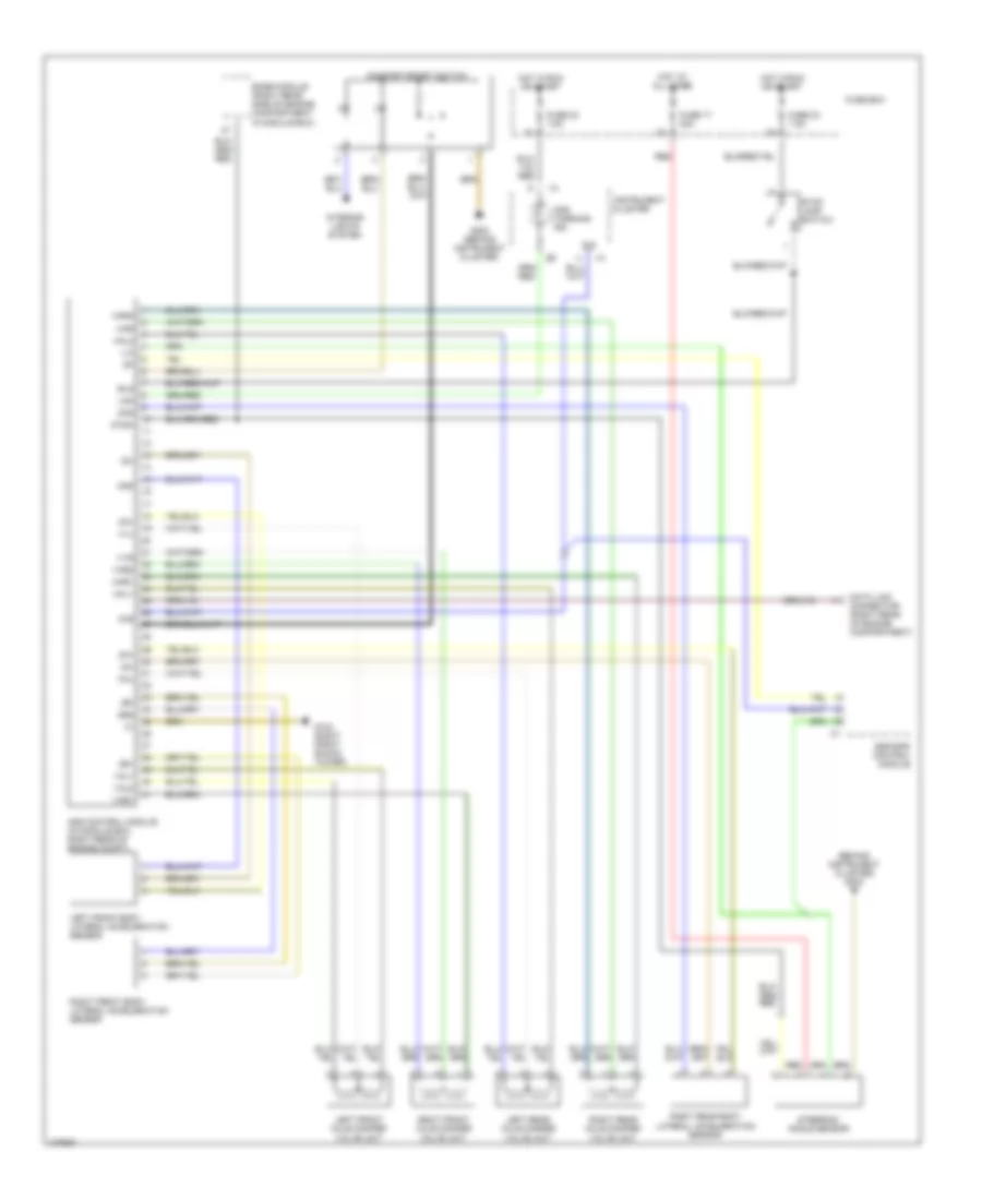
Electronic Suspension Wiring Diagram for Mercedes-Benz S500 1997
List of elements for Electronic Suspension Wiring Diagram for Mercedes-Benz S500 1997:
- (behind instrument cluster) g202
- 61e
- 61e
- 87isa
- Ads control module (in module box, right rear of engine compt)
- Ads warning ind.
- Base module (right rear side of engine compartment, in module box)
- Bls
- Comfort/sport switch
- Data link connector (right rear of engine compartment)
- Esp/sps control module
- Fuse 17 20a
- Fuse 23 7.5a
- Fuse 24 7.5a
- Fuse box
- G103 (right front shock tower)
- G202 (behind instrument cluster)
- Hal
- Hal1
- Hal2
- Har
- Har1
- Har2
- Hot at all times
- Hot in run or start
- Instrument cluster
- Interior lights system
- Lam
- Left front axle damper valve unit
- Left front body lateral acceleration sensor
- Left rear axle damper valve unit
- Red
- Right front axle damper valve unit
- Right front body lateral acceleration sensor
- Right rear axle damper valve unit
- Right rear body lateral acceleration sensor
- Steering angle sensor
- Stop lamp switch
- Val1
- Val2
- Var1
- Var2
- Vvl
- Vvr
- Za+
- Za-
- Zas
- Zr+
- Zr-
- Zrs
 Čeština
 Dansk
Dansk Deutsch
 Ελληνικά
 English
 English
 Español
 Suomi
Suomi Français
 Français
 עברית
עברית Hrvatski
 Magyar
 日本語
日本語 한국어
한국어 Nederlands
 Polski
 Português
 Português
 Română
 Русский
 Slovenčina
 Slovenščina
 Svenska
 Türkçe
 中文 (中国)
 Italiano