СИСТЕМА ПЕРЕДАЧИ ДАННЫХ
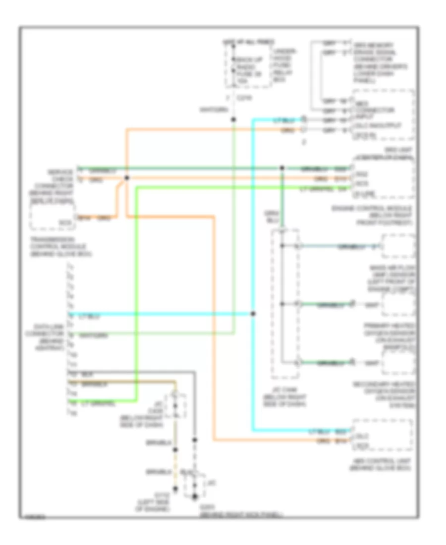
Электросхема линии передачи данных CAN для Acura 2.5TL 1998
Электросхема линии передачи данных CAN для Acura 2.5TL 1998 - Список элементов:
- (behind ashtray)
- Abs control unit (behind glove box)
- B14
- B22
- Back up radio fuse 39 10a
- C216
- Connector (behind driver's lower dash panel)
- Connector (behind right side of dash)
- D13
- D22
- Data link connector
- Dlc
- Dlc in/output
- Engine control module (below right front footrest)
- G112 (left side of engine)
- G203 (behind right kick panel)
- Hot at all times
- J/c
- J/c c436 (below right side of dash)
- J/c c444 (below right side of dash)
- K-line
- Mass air flow (maf) sensor (left front of engine compt)
- Mes connector input
- Primary heated oxygen sensor (on exhaust manifold)
- Scs
- Scs in
- Secondary heated oxygen sensor (on exhaust system)
- Service check
- Sg2
- Srs memory erase signal
- Srs unit (center of dash)
- Transmission control module (behind glove box)
- Under- hood fuse/ relay box
 Čeština
 Dansk
Dansk Deutsch
 Ελληνικά
 English
 English
 Español
 Suomi
Suomi Français
 Français
 עברית
עברית Hrvatski
 Magyar
 日本語
日本語 한국어
한국어 Nederlands
 Polski
 Português
 Português
 Română
 Русский
 Slovenčina
 Slovenščina
 Svenska
 Türkçe
 中文 (中国)
 Italiano