ENGINE PERFORMANCE
2.4L
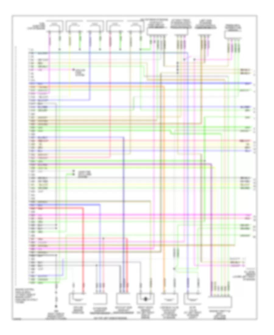
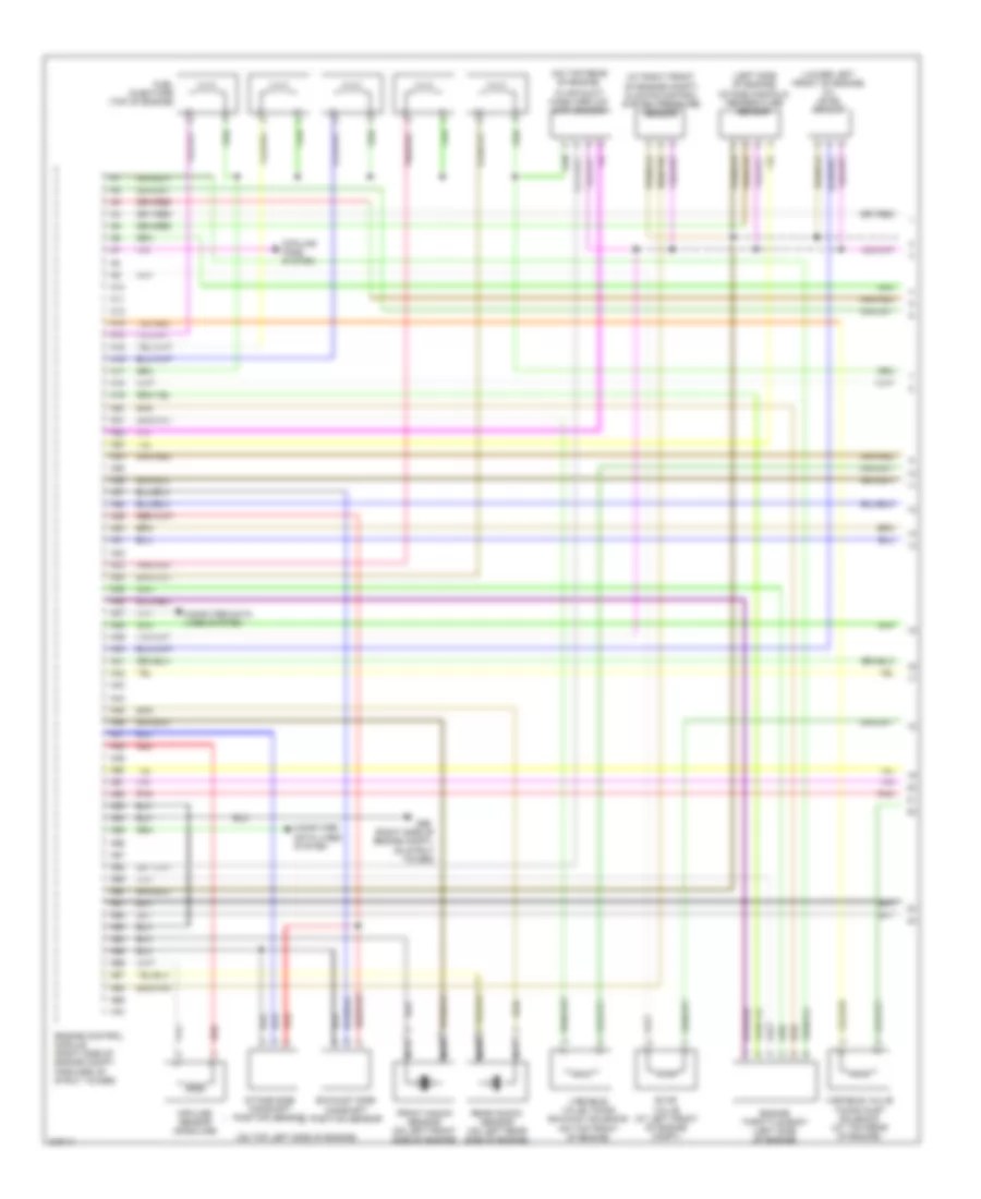
2.4L, Engine Performance Wiring Diagram (1 of 3) for Volvo V70 R 2005
List of elements for 2.4L, Engine Performance Wiring Diagram (1 of 3) for Volvo V70 R 2005:
- (at right front of engine compt) climate control pressure sensor
- (left side of engine) intake manifold pressure sensor
- (on top left side of engine)
- (on top rear of engine,
- A10
- A11
- A12
- A13
- A14
- A15
- A16
- A17
- A18
- A19
- A20
- A21
- A22
- A23
- A24
- A25
- A26
- A27
- A28
- A29
- A30
- A31
- A32
- A33
- A34
- A35
- A36
- A37
- A38
- A39
- A40
- A41
- A42
- A43
- A44
- A45
- A46
- A47
- A48
- A49
- A50
- A51
- A52
- A53
- A54
- A55
- A56
- A57
- A58
- A59
- A60
- A61
- A62
- A63
- A64
- A65
- A66
- A67
- A68
- A69
- A70
- Computer data lines system
- Cooling fans system
- Engine control module (ecm) (at right side of engine compt, forward of strut tower)
- Engine throttle body (left side of engine)
- Evap valve (at left front of engine compt)
- Exhaust side camshaft position sensor
- Front knock sensor (on left front side of engine)
- Fuel injectors (top of engine)
- G96 (right side of engine compt, on strut tower)
- Impulse sensor (gasoline)
- In air duct) mass airflow (maf) sensor
- Intake side camshaft position sensor
- Oil level sensor (lower left front of engine)
- Pnk
- Pressure & temperature sensor
- Red
- Variable valve timing inlet solenoid (at top rear of engine)
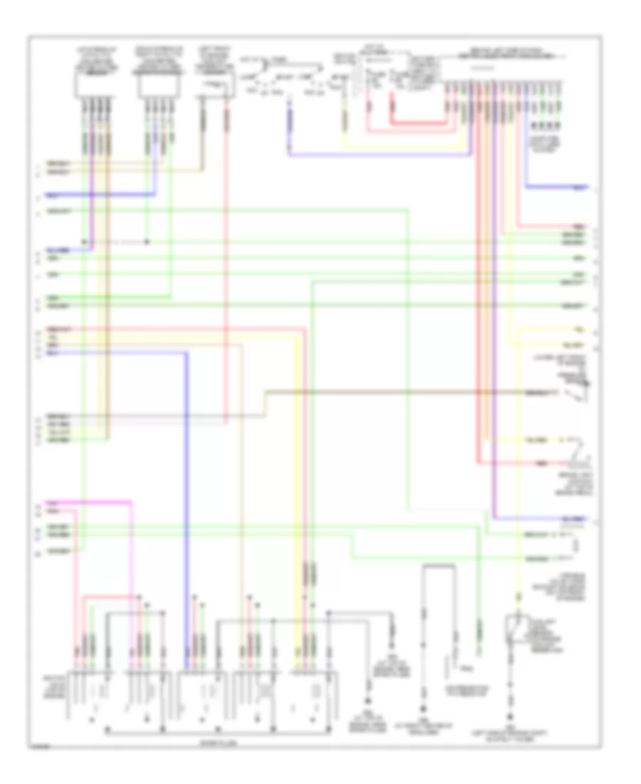
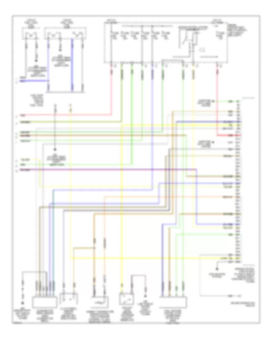
2.4L, Engine Performance Wiring Diagram (2 of 3) for Volvo V70 R 2005
List of elements for 2.4L, Engine Performance Wiring Diagram (2 of 3) for Volvo V70 R 2005:
- (behind left side of dash) central electronic module (cem)
- (down stream of right catalytic converter) heated oxygen sensor diagnosis 1
- (left front of engine) coolant temperature sensor
- (lower left front of engine) oil pressure sensor
- (up stream of catalytic converter) heated oxygen sensor
- A16
- Acc
- Air preheating ptc resistor
- B11
- B16
- Battery fuse box (next to battery, in cargo compt)
- Brake light contact (at top of brake pedal)
- C14
- C21
- C22
- C34
- C35
- Computer data lines system
- Coolant level sensor (on engine coolant reservoir)
- D16
- D34
- D49
- D60
- Fuse e4 15a
- Fuse e5 10a
- G88 (at top of engine, near spark plugs)
- G89 (at top of engine, near spark plugs)
- G93 (left side of engine compt, on strut tower)
- G96 (at front center of headliner)
- Hot at all times
- Ignition coils (top of engine)
- Ignition switch
- Lock
- Nca
- Pnk
- Red
- Run
- Spark plugs
- Start
- Variable valve timing exhaust solenoid (on top front of engine)
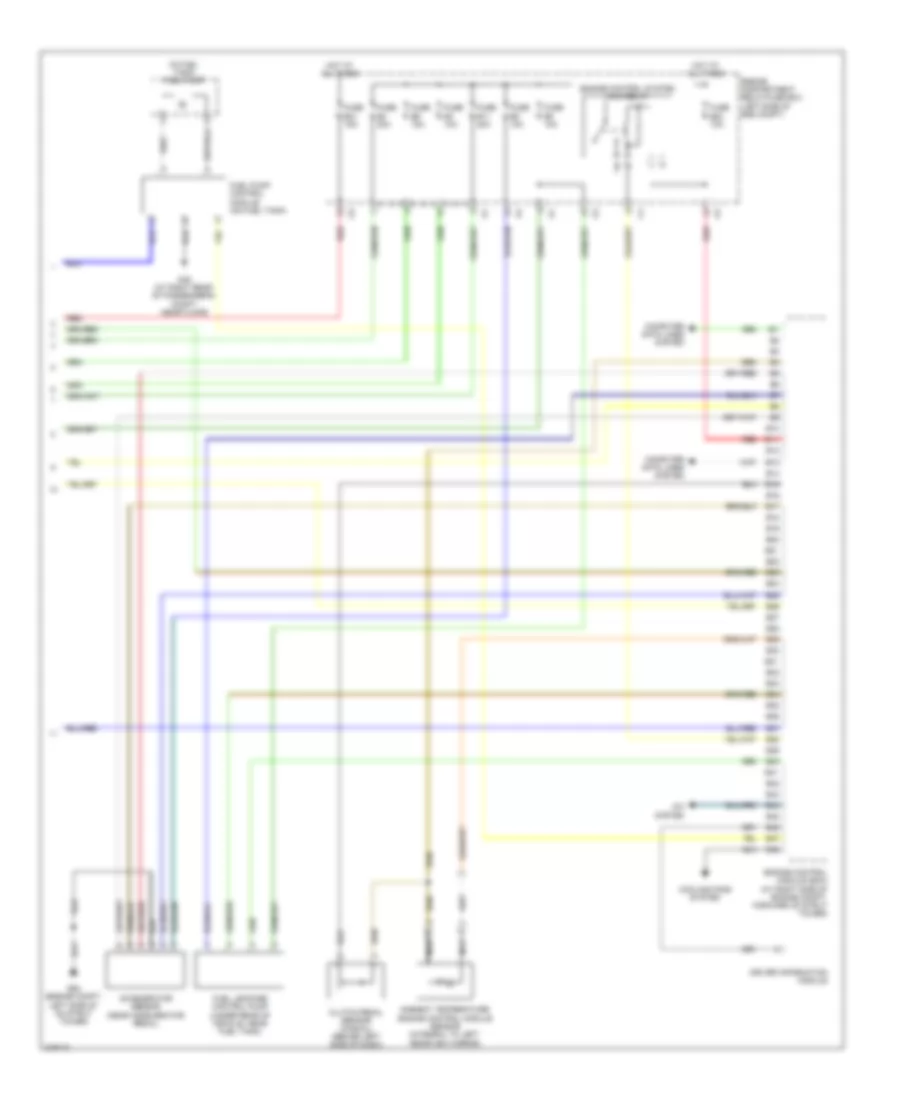
2.4L, Engine Performance Wiring Diagram (3 of 3) for Volvo V70 R 2005
List of elements for 2.4L, Engine Performance Wiring Diagram (3 of 3) for Volvo V70 R 2005:
- (in fuel tank) fuel pump
- A/c system
- Accelerator sensor (near accelerator pedal)
- Ambient temperature engine control module sensor (integral to left rearview mirror)
- B10
- B11
- B12
- B13
- B14
- B15
- B16
- B17
- B18
- B19
- B20
- B21
- B22
- B23
- B24
- B25
- B26
- B27
- B28
- B29
- B30
- B31
- B32
- B33
- B34
- B35
- B36
- B37
- B38
- B39
- B40
- B41
- B42
- B43
- B44
- B45
- B46
- B47
- B48
- Clutch pedal sensor (manual) (behind left side of dash)
- Computer data lines system
- Cooling fans system
- Driver information module
- Engine compartment relay/fuse box (left side of eng compt)
- Engine control module (ecm) (at right side of engine compt, forward of strut tower)
- Engine control system main relay
- Fuel leakage control pump (under rear of vehicle, near fuel tank)
- Fuel pump control module (on fuel tank)
- Fuse b11 20a
- Fuse b21 15a
- Fuse b23 10a
- Fuse b3 10a
- Fuse b4 20a
- Fuse b5 10a
- Fuse b6 15a
- Fuse b8 10a
- G48 (at right rear of passenger's compt, near floor)
- G93 (engine compt, left side of on strut tower)
- Hot at all times
- Nca
- Red
2.4L TURBO
2.4L Turbo, Engine Performance Wiring Diagram (1 of 3) for Volvo V70 R 2005
List of elements for 2.4L Turbo, Engine Performance Wiring Diagram (1 of 3) for Volvo V70 R 2005:
- (at right front of engine compt) climate control system pressure sensor
- (left side of engine) intake manifold temperature sensor
- (lower left front of engine) oil level sensor
- (on top left side of engine)
- (on top rear of engine,
- (right side of engine compt, on strut tower)
- A10
- A11
- A12
- A13
- A14
- A15
- A16
- A17
- A18
- A19
- A20
- A21
- A22
- A23
- A24
- A25
- A26
- A27
- A28
- A29
- A30
- A31
- A32
- A33
- A34
- A35
- A36
- A37
- A38
- A39
- A40
- A41
- A42
- A43
- A44
- A45
- A46
- A47
- A48
- A49
- A50
- A51
- A52
- A53
- A54
- A55
- A56
- A57
- A58
- A59
- A60
- A61
- A62
- A63
- A64
- A65
- A66
- A67
- A68
- A69
- A70
- Computer data lines system
- Cooling fans system
- Engine control module (right side of engine compt, forward of strut tower)
- Engine throttle body (left side of engine)
- Evap valve (at left front of engine compt)
- Exhaust side camshaft position sensor
- Front knock sensor (on left front side of engine)
- Fuel injectors (top of engine)
- G96
- Impulse sensor (gasoline)
- In air duct) mass airflow (maf) sensor
- Intake side camshaft position sensor
- Nca
- Pnk
- Rear knock sensor (on left rear side of engine)
- Red
- Variable valve timing exhaust solenoid (on top front of engine)
- Variable valve timing inlet solenoid (at top rear of engine)
2.4L Turbo, Engine Performance Wiring Diagram (2 of 3) for Volvo V70 R 2005
List of elements for 2.4L Turbo, Engine Performance Wiring Diagram (2 of 3) for Volvo V70 R 2005:
- (behind left side of dash) central electronic module (cem)
- (left front of engine)
- (up stream of catalytic converter) heated oxygen sensor
- A16
- Acc
- Air preheating ptc resistor
- B11
- B16
- Battery fuse box (next to battery, in cargo compt)
- Brake light contact (at top of brake pedal)
- C14
- C21
- C22
- C34
- C35
- Computer data lines system
- Coolant temperature sensor
- D16
- D34
- D49
- D60
- Fuse e4 15a
- Fuse e5 10a
- G88 (at top of engine, near spark plugs)
- G89 (at top of engine, near spark plugs)
- G96 (at front center of headliner)
- Heated oxygen sensor diagnosis 1 (down stream of right catalytic converter)
- Hot at all times
- Ignition coils (top of engine)
- Ignition switch
- Lock
- Nca
- Off
- Oil pressure sensor (on left side of engine)
- Pnk
- Pressure & temperature sensor
- Red
- Run
- Spark plugs
- Start
- Turbo control valve (top rear of engine)
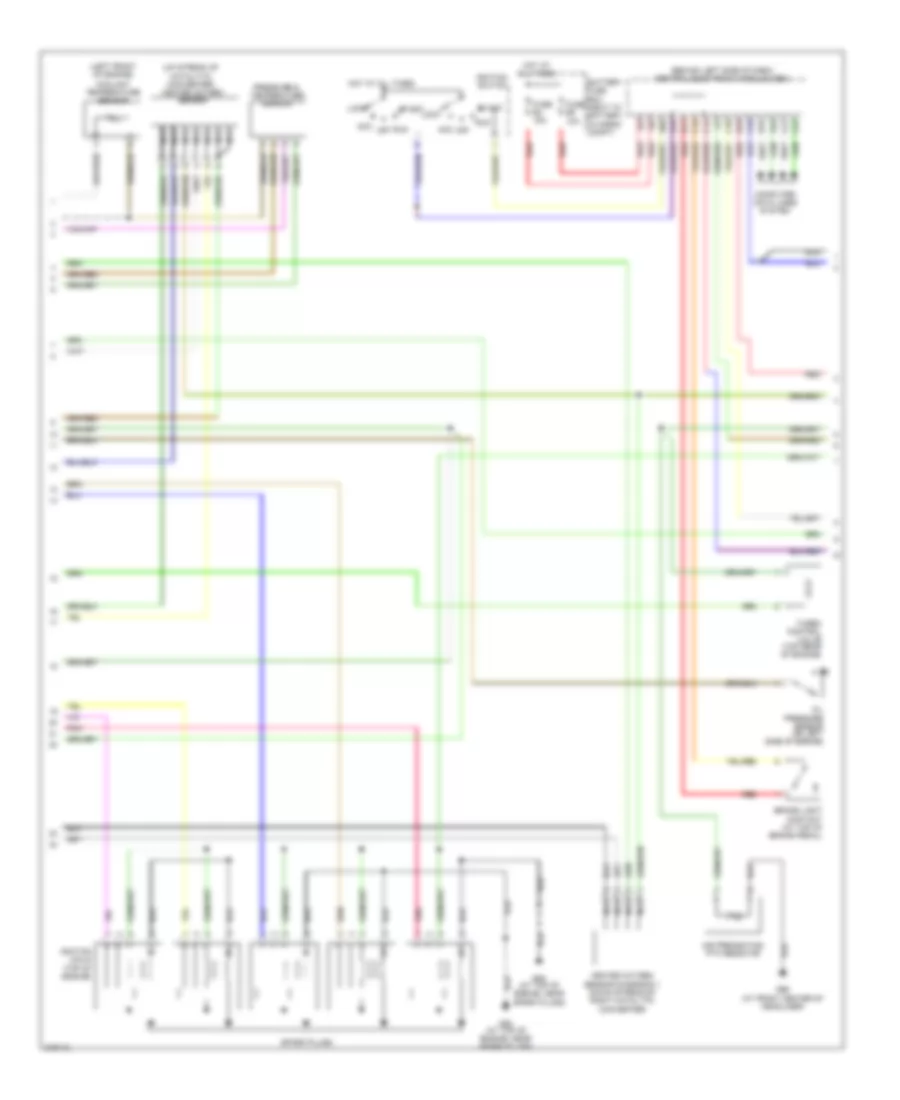
2.4L Turbo, Engine Performance Wiring Diagram (3 of 3) for Volvo V70 R 2005
List of elements for 2.4L Turbo, Engine Performance Wiring Diagram (3 of 3) for Volvo V70 R 2005:
- (top of fuel tank) fuel pump
- (v70r)
- Accelerator pedal sensor (near accelerator pedal)
- Ambient temperature engine control module sensor (integral to left rearview mirror)
- B10
- B11
- B12
- B13
- B14
- B15
- B16
- B17
- B18
- B19
- B20
- B21
- B22
- B23
- B24
- B25
- B26
- B27
- B28
- B29
- B30
- B31
- B32
- B33
- B34
- B35
- B36
- B37
- B38
- B39
- B40
- B41
- B42
- B43
- B44
- B45
- B46
- B47
- B48
- Clutch pedal sensor (manual) (behind left side of dash)
- Computer data lines system
- Coolant level sensor (on engine coolant reservoir)
- Cooling fans system
- Driver information module
- Engine compartment relay/fuse box (left side of eng compt)
- Engine control module (ecm) (at right side of engine compt, forward of strut tower)
- Engine control system main relay
- Fuel leakage control pump (under rear of vehicle, near fuel tank)
- Fuel pump control module (top of fuel tank)
- Fuse b11 20a
- Fuse b21 15a
- Fuse b23 10a
- Fuse b4 20a
- Fuse b5 15a
- Fuse b6 15a
- Fuse b8 10a
- G48 (at right rear of passenger's compt, near floor)
- G93 (engine compt, left side of on strut tower)
- G93 (left side of engine compt, on strut tower)
- Hot at all times
- Nca
- Red
2.5L TURBO
2.5L Turbo, Engine Performance Wiring Diagram (1 of 3) for Volvo V70 R 2005
List of elements for 2.5L Turbo, Engine Performance Wiring Diagram (1 of 3) for Volvo V70 R 2005:
- (at right front of engine compt) climate control system pressure sensor
- (left side of engine) intake manifold temperature sensor
- (lower left front of engine) oil level sensor
- (on top left side of engine)
- (on top rear of engine,
- (right side of engine compt, on strut tower)
- A10
- A11
- A12
- A13
- A14
- A15
- A16
- A17
- A18
- A19
- A20
- A21
- A22
- A23
- A24
- A25
- A26
- A27
- A28
- A29
- A30
- A31
- A32
- A33
- A34
- A35
- A36
- A37
- A38
- A39
- A40
- A41
- A42
- A43
- A44
- A45
- A46
- A47
- A48
- A49
- A50
- A51
- A52
- A53
- A54
- A55
- A56
- A57
- A58
- A59
- A60
- A61
- A62
- A63
- A64
- A65
- A66
- A67
- A68
- A69
- A70
- Computer data lines system
- Cooling fans system
- Engine control module (right side of engine compt, forward of strut tower)
- Engine throttle body (left side of engine)
- Evap valve (at left front of engine compt)
- Exhaust side camshaft position sensor
- Front knock sensor (on left front side of engine)
- Fuel injectors (top of engine)
- G96
- Impulse sensor (gasoline)
- In air duct) mass airflow (maf) sensor
- Intake side camshaft position sensor
- Nca
- Pnk
- Rear knock sensor (on left rear side of engine)
- Red
- Variable valve timing exhaust solenoid (on top front of engine)
- Variable valve timing inlet solenoid (at top rear of engine)
2.5L Turbo, Engine Performance Wiring Diagram (2 of 3) for Volvo V70 R 2005
List of elements for 2.5L Turbo, Engine Performance Wiring Diagram (2 of 3) for Volvo V70 R 2005:
- (behind left side of dash) central electronic module (cem)
- (left front of engine)
- (up stream of catalytic converter) heated oxygen sensor
- A16
- Acc
- Air preheating ptc resistor
- B11
- B16
- Battery fuse box (next to battery, in cargo compt)
- Brake light contact (at top of brake pedal)
- C14
- C21
- C22
- C34
- C35
- Computer data lines system
- Coolant temperature sensor
- D16
- D34
- D49
- D60
- Fuse e4 15a
- Fuse e5 10a
- G88 (at top of engine, near spark plugs)
- G89 (at top of engine, near spark plugs)
- G96 (at front center of headliner)
- Heated oxygen sensor diagnosis 1 (down stream of right catalytic converter)
- Hot at all times
- Ignition coils (top of engine)
- Ignition switch
- Lock
- Nca
- Off
- Oil pressure sensor (on left side of engine)
- Pnk
- Pressure & temperature sensor
- Red
- Run
- Spark plugs
- Start
- Turbo control valve (top rear of engine)
2.5L Turbo, Engine Performance Wiring Diagram (3 of 3) for Volvo V70 R 2005
List of elements for 2.5L Turbo, Engine Performance Wiring Diagram (3 of 3) for Volvo V70 R 2005:
- (top of fuel tank) fuel pump
- (v70r)
- Accelerator pedal sensor (near accelerator pedal)
- Ambient temperature engine control module sensor (integral to left rearview mirror)
- B10
- B11
- B12
- B13
- B14
- B15
- B16
- B17
- B18
- B19
- B20
- B21
- B22
- B23
- B24
- B25
- B26
- B27
- B28
- B29
- B30
- B31
- B32
- B33
- B34
- B35
- B36
- B37
- B38
- B39
- B40
- B41
- B42
- B43
- B44
- B45
- B46
- B47
- B48
- Clutch pedal sensor (manual) (behind left side of dash)
- Computer data lines system
- Coolant level sensor (on engine coolant reservoir)
- Cooling fans system
- Driver information module
- Engine compartment relay/fuse box (left side of eng compt)
- Engine control module (ecm) (at right side of engine compt, forward of strut tower)
- Engine control system main relay
- Fuel leakage control pump (under rear of vehicle, near fuel tank)
- Fuel pump control module (top of fuel tank)
- Fuse b11 20a
- Fuse b21 15a
- Fuse b23 10a
- Fuse b4 20a
- Fuse b5 15a
- Fuse b6 15a
- Fuse b8 10a
- G48 (at right rear of passenger's compt, near floor)
- G93 (engine compt, left side of on strut tower)
- G93 (left side of engine compt, on strut tower)
- Hot at all times
- Nca
- Red

 Čeština
 Dansk
Dansk Deutsch
 Ελληνικά
 English
 English
 Español
 Suomi
Suomi Français
 Français
 עברית
עברית Hrvatski
 Magyar
 日本語
日本語 한국어
한국어 Nederlands
 Polski
 Português
 Português
 Română
 Русский
 Slovenčina
 Slovenščina
 Svenska
 Türkçe
 中文 (中国)