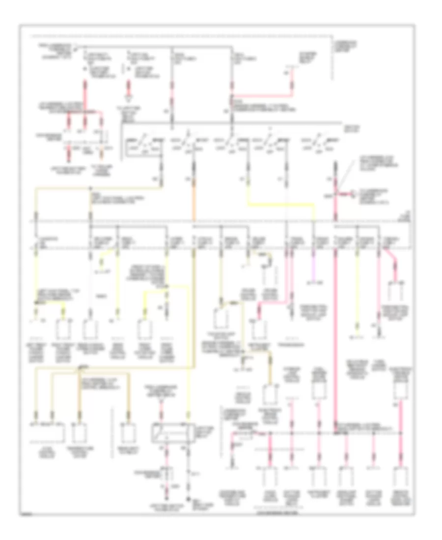
POWER DISTRIBUTION
Power Distribution Wiring Diagram (1 of 3) for Chevrolet Astro 1997


List of elements for Power Distribution Wiring Diagram (1 of 3) for Chevrolet Astro 1997:
- (engine harness, 24 cm from underhood fuse-relay center) s109
- (front of dash, 18 cm from fwd lamp harness breakout)
- (i/p harness, 17 cm from cluster breakout)
- (i/p harness, 2 cm from headlamp switch breakout) s211 red
- (i/p harness, 21 cm from heater a/c control breakout)
- (i/p harness, 4 cm from headlamp switch breakout)
- (i/p harness, 9 cm from cluster breakout) s220
- (left door harness, 4 cm from power door lock switch connector breakout)
- (left door harness, 6 cm from outside rearview mirror breakout)
- (power seat harness, 7 cm from left power seat breakout)
- (right door harness, 4 cm from power door lock switch breakout)
- (vanity mirror harness, 7 cm from left vanity mirror breakout) s237
- A/c comp mini fuse k11 10a
- A/c enable relay
- A/c maxi fuse m3 30a
- A12
- Abs maxi fuse m4 60a
- Audio alarm module
- Aux pwr fuse 7 25a
- Batt maxi fuse 7 50a
- Battery
- Blower motor resistor and relay pack
- C207
- C222
- Center dome lamp
- Center dome/reading lamps
- Cig ltr fuse 13 20a
- Cigarette lighter
- Convenience center
- Ctsy fuse 3 20a
- Data link connector
- Daytime running lamp diode
- Door lock control module
- Door lock relay
- Driver seat adjuster switch
- Drl fuse 15 10a
- Ecm-b mini fuse f11 20a
- Electronic brake control module
- Electronic variable orifice module
- From underhood a fuse-relay center above
- Front auxiliary power outlets
- Front dome/ reading lamps
- Fuel pump relay
- Fusible link
- G901 (right "a" pillar)
- G999 (left "d" pillar)
- Generator
- Headlamp and panel dimmer
- Headlamp and panel dimmer switch
- Horn mini fuse h11 20a
- Horn relay
- Hvac control module
- I/p compartment lamp
- I/p fuse block
- Illum fuse 14 10a
- Interior lamp control module
- Interior lights
- Interior lights system
- Left courtesy lamp
- Left door courtesy lamp
- Left power door lock switch
- Left vanity lamp
- Liftgate lock/latch module
- Lighting maxi fuse 8 40a
- Locks/ seats cb 30a
- Oil pressure switch and sender
- Outside rearview mirror switch
- Passenger seat adjuster switch
- Pk lps fuse 9 20a
- Radio
- Radio batt fuse 19 10a
- Rear auxiliary power outlet
- Rear defog mini fuse f9 30a
- Rear dome lamp
- Rear heat- a/c relay
- Red
- Relay center
- Remote control door lock receiver
- Right courtesy lamp
- Right door courtesy lamp
- Right power door lock switch
- Right stepwell lamp
- Right vanity lamp
- Rr heat a/c maxi fuse m2 30a
- S132
- S213
- S223
- S227
- S319
- S322 (left side of vehicle, 4 cm from side door harness breakout)
- S500
- S600
- Starter solenoid
- Steering fuse 21 10a
- Stop/haz fuse 1 20a
- Subwoofer amplifier
- Switch
- System
- Tcc/stoplamp switch
- To underhood fuse-relay center (diagram 2 of 3)
- To underhood fuse-relay center below
- Turn/ hazard switch
- Underhood fuse-
- Underhood fuse-relay center
- Upfitter battery power stud
- Vehicle control module
Power Distribution Wiring Diagram (2 of 3) for Chevrolet Astro 1997
List of elements for Power Distribution Wiring Diagram (2 of 3) for Chevrolet Astro 1997:
- (front of dash, 4 cm from bulkhead grommet, toward windshield washer motor) s134
- (i/p harness, 14 cm from heater a/c control breakout)
- (i/p harness, 2 cm from temperature control motor breakout) s303
- (i/p harness, 6 cm from connector at lower steering column)
- (left kick panel, 7 cm from park brake switch breakout) s305
- (not used)
- Acc
- Air bag fuse 10 10a
- Audio alarm module
- B10
- B17
- Brake fuse 18 10a
- C200
- C214
- Center (diagram 1 of 3)
- Compass and temperature display module
- Convenience center
- Crank fuse 8 10a
- Cruise control module
- Cruise control switch
- Cruise fuse 6 10a
- Daytime running lamps module
- Daytime running lamps relay
- E nca
- Electronic brake control module
- Electronic variable orifice module
- From underhood fuse-relay b
- From underhood fuse-relay center above
- Front pulse wiper/ washer switch
- Front wiper motor and module
- Fuel/ sender gauge module
- G201 (right side of dash)
- Gauges fuse 4 10a
- Headlamp and panel dimmer switch
- Htr-a/c fuse 12 20a
- Hvac control module
- I/p fuse block
- Ign-a maxi fuse 6 40a
- Ign-b maxi fuse 5 40a
- Ignition switch
- Inflatable restraint sensing diagnostic module
- Instrument cluster
- Interior lamp control module
- Left front power window master switch
- Lock
- Nca
- Off
- Park/neutral position and backup lamp switch
- Pnk
- Pnk (i/p harness, 4 cm from headlamp switch breakout) s213
- Pnk c207
- Radio
- Radio fuse 17 10a
- Rear heat- a/c relay
- Rear radio control module
- Rear window wiper/washer switch
- Red
- Remote control door lock receiver
- Right front power window master switch
- Rr wiper fuse 23 20a
- Run
- S108 (engine harness, 17 cm from underhood fuse-relay center)
- S111
- S114
- S203 (left kick panel, 4 cm from bulkhead connector)
- S205
- S224
- Start
- Starter enable relay
- Tcc/stoplamp switch
- Temperature control motor
- To trailer wiring harness
- To underhood fuse-relay center (diagram 3 of 3)
- To upfitter ignition relay below
- Trans fuse 20 10a
- Transmission
- Turn-b/u fuse 4 10a
- Turn/ hazard switch
- Underhood fuse-relay center
- Upfit-batt maxi fuse p8 30a
- Upfit-ign maxi fuse p7 30a
- Upfitter battery power stud
- Upfitter ignition power stud
- Upfitter ignition relay
- Vehicle control module
- Windows cb 30a
- Wiper fuse 11 25a
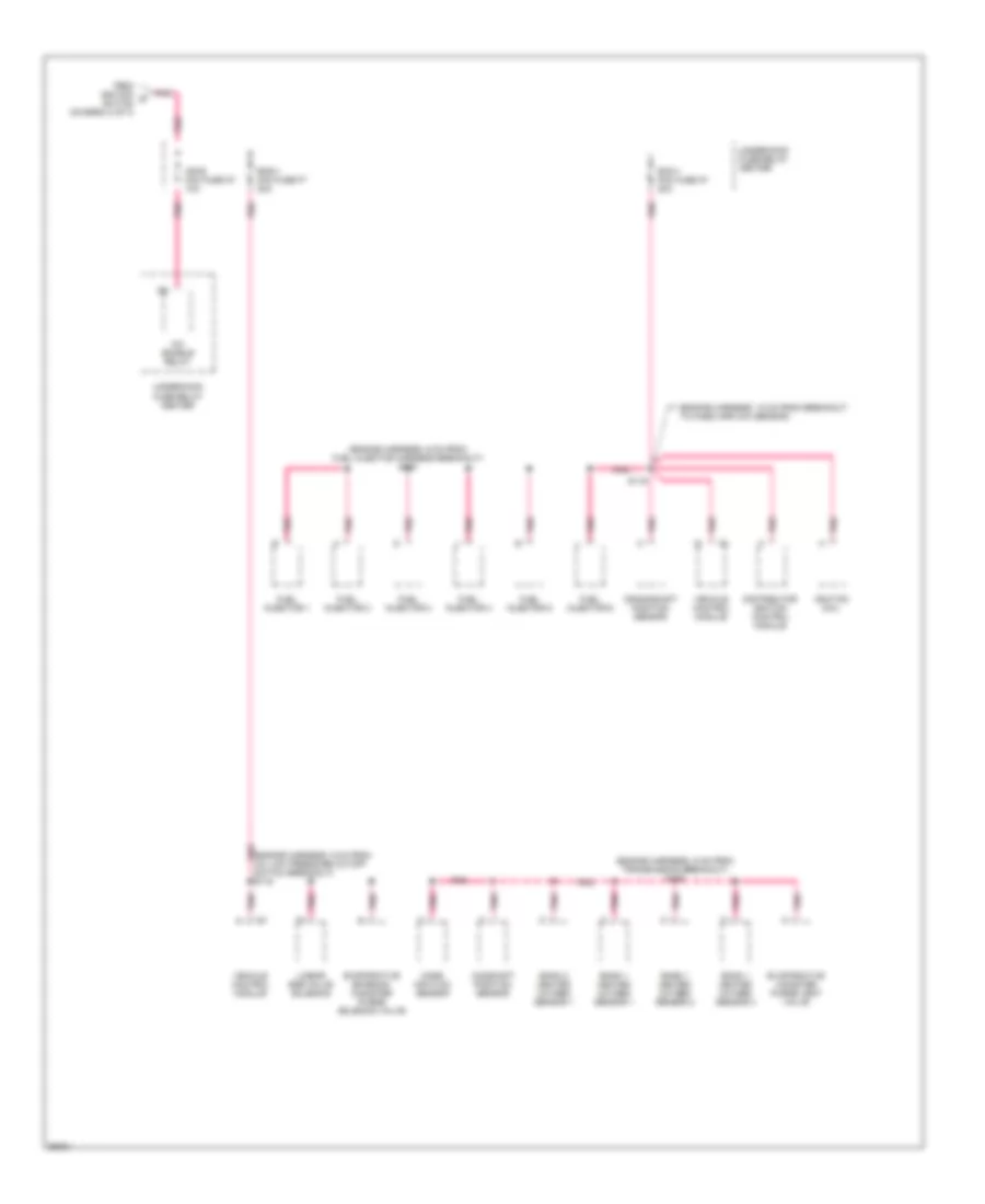
Power Distribution Wiring Diagram (3 of 3) for Chevrolet Astro 1997
List of elements for Power Distribution Wiring Diagram (3 of 3) for Chevrolet Astro 1997:
- (engine harness, 18 cm from breakout to mass airflow sensor)
- (engine harness, 6 cm from fuel injector harness breakout) s123
- (engine harness, 6 cm from transmission breakout) s126
- (engine harness, 9 cm from a/c low pressure cutoff switch breakout) s119
- A/c enable relay
- Bank 1 heated oxygen sensor 1
- Bank 1 heated oxygen sensor 2
- Bank 1 heated oxygen sensor 3
- Bank 2 heated oxygen sensor 1
- Camshaft position sensor
- Crankshaft position sensor
- Distributor ignition control module
- Ecm-1 mini fuse k7 20a
- Eng-1 mini fuse f7 20a
- Evaporative canister purge vent valve
- Evaporative emission canister purge solenoid valve
- From ignition d switch (diagram 2 of 3)
- Fuel injector 1
- Fuel injector 2
- Fuel injector 3
- Fuel injector 4
- Fuel injector 5
- Fuel injector 6
- Ign-e mini fuse m7 10a
- Ignition coil
- Linear egr valve solenoid
- Mass air flow sensor
- Pnk
- S116
- Underhood fuse-relay center
- Vehicle control module

 Čeština
 Dansk
Dansk Deutsch
 Ελληνικά
 English
 English
 Español
 Suomi
Suomi Français
 Français
 עברית
עברית Hrvatski
 Magyar
 日本語
日本語 한국어
한국어 Nederlands
 Polski
 Português
 Português
 Română
 Русский
 Slovenčina
 Slovenščina
 Svenska
 Türkçe
 中文 (中国)