ENGINE PERFORMANCE
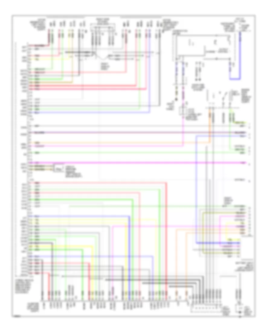
Hybrid System Wiring Diagram (1 of 3) for Toyota Prius 2003
List of elements for Hybrid System Wiring Diagram (1 of 3) for Toyota Prius 2003:
- (right side of dash)
- (right side of dash) j/c 8, j/c 9
- As1
- As1g
- Battery input relay (left rear of luggage compt)
- C10
- C11
- Cbi
- Cei
- Charge
- Circuit breaker sensor (left side of engine compt)
- Combination meter
- Compt) m3
- Computer data lines system
- Con1
- Con2
- Cvrsw
- Engine room r/b 2 (rear of engine compt)
- G-finv
- G-ginv
- G-invt
- G-iva
- G-ivb
- G-iwa
- G-iwb
- G-sdn
- G-sinv
- G-uu
- G-vu
- G-wu
- G1t
- Gauge fuse 10a
- Gcs
- Gcsg
- Gfiv
- Giva
- Givb
- Givg
- Giwa
- Giwb
- Gmt
- Gmtg
- Gnd
- Grf
- Grfg
- Gsdn
- Gsiv
- Gsn
- Gsng
- Guu
- Gvu
- Gwu
- H10
- H11
- H12
- Hot at all times
- Hybrid vehicle control ecu (behind right side of dash, forward of glove box)
- I10
- I11
- I12
- I13
- I14
- Igct
- Igct relay
- Ih (right kick panel)
- Instrument panel j/b (left end of dash)
- Inverter (left side of engine compt)
- J/c 1 (left end of dash)
- J/c 27, j/c 28 (upper left center j28
- J/c 7 (right end of dash)
- J27
- M-finv
- M-ginv
- M-invt
- M-iva
- M-ivb
- M-iwa
- M-iwb
- M-sdn
- M-sinv
- M-uu
- M-vu
- M-wu
- Mcs
- Mcsg
- Mfiv
- Mit
- Miva
- Mivb
- Mivg
- Miwa
- Miwb
- Mmt
- Motor generator 1 (left front of engine compt)
- Motor generator 2 (left front of engine mrf
- Mrel
- Mrf
- Mrfg
- Msdn
- Msiv
- Msn
- Msng
- Muu
- Mvu
- Mwu
- Nca
- Nmtg
- Nodd
- Of dash)
- Output control
- Pnk
- Red
- Spdi
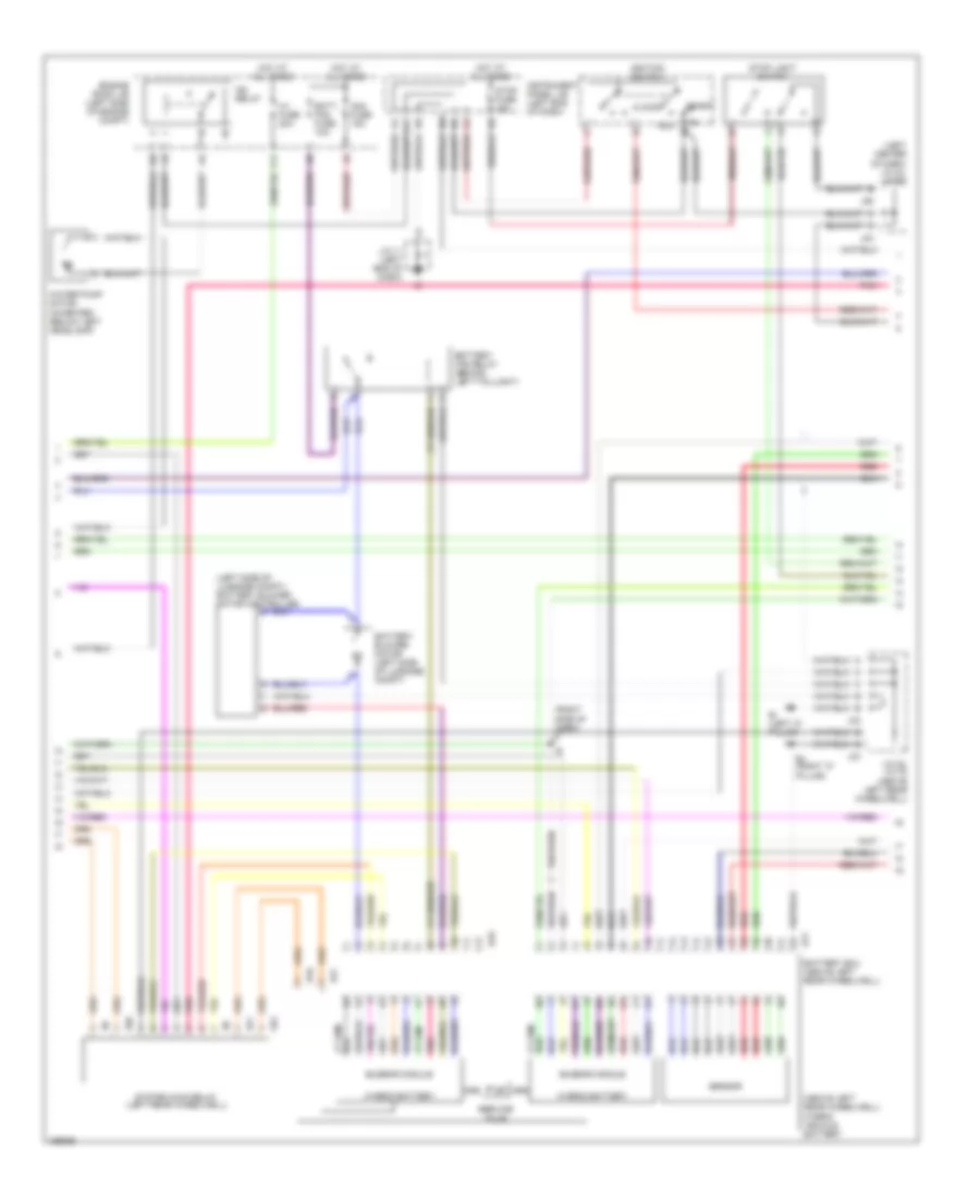
Hybrid System Wiring Diagram (2 of 3) for Toyota Prius 2003
List of elements for Hybrid System Wiring Diagram (2 of 3) for Toyota Prius 2003:
- (above left rear wheelwell) hybrid vehicle battery
- (left center of dash) j/c 24, j/c 25
- (left side of luggage compt) battery blower motor controller
- (right side of dash)
- Acc
- Am2 fuse 15a
- B17
- B18
- Batt fan fuse 10a
- Battery blower motor (left side of luggage compt)
- Battery ecu (above left rear wheelwell)
- Battery fan relay (behind left taillight)
- Bi (left "c" pillar)
- Bj (right "c"
- Busbar module
- Engine room j/b (left side of engine compt)
- F11
- G11
- H16
- H17
- Hot at all times
- Hv fuse 20a
- Hybrid battery
- Ig2 relay
- Ignition switch
- Instrument panel j/b (left end of dash)
- J/c 11 (left end of dash)
- J/c 32, j/c 33 (above left rear wheelwell)
- J24
- J25
- J32
- J33
- Lock
- Pillar)
- Pnk
- Red
- S10
- S11
- S12
- Sensor
- Service plug
- Start
- Stop fuse 15a
- Stop light switch
- System main relay (left rear wheelwell)
- Water pump motor (inverter) (below left headlamp)
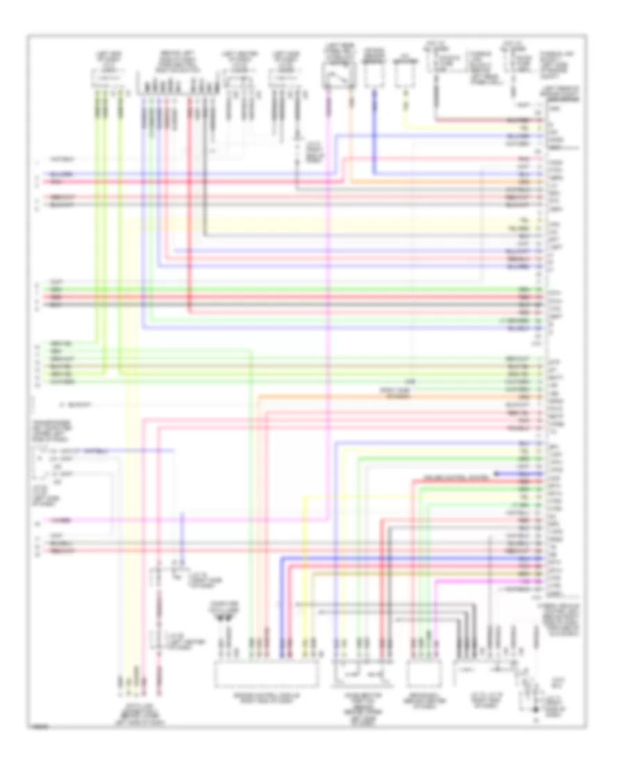
Hybrid System Wiring Diagram (3 of 3) for Toyota Prius 2003
List of elements for Hybrid System Wiring Diagram (3 of 3) for Toyota Prius 2003:
- (behind left side of dash) park/neutral position switch
- (left center of dash) j/c 24, j/c 25
- (left end of dash) j/c 2, j/c 3
- (left rear of engine compt) converter
- (left rear wheelwell)
- (left side of dash) j/c 22, j/c 23
- (right side of dash)
- +b1
- +b2
- A j19
- A/c amplifier
- Abfs
- Accelerator position sensor (behind upper
- Air bag sensor assembly
- Amd
- Batt
- Brake ecu (behind center of dash)
- Bth+
- Bth-
- Ccs
- Computer data lines system
- Con3
- Cruise control system
- Data link connector 3 (behind lower left side of dash)
- Dc/dc fuse 100a
- Dc/dc-s fuse 5a
- Dth+
- Dth-
- E10
- Engine control module (right end of dash)
- Eom
- Ep1
- Ep2
- Estp
- Eth+
- Eth-
- Fcvc
- Fusible link block 1 (left side of engine compt)
- Fusible link block 2 (behind left rear wheelwell)
- Gnd1
- Gnd2
- Gsft
- H13
- H14
- Hai
- Hao
- Hot at all times
- Htb+
- Htb-
- Htd+
- Htd-
- Hte+
- Hte-
- Hybrid vehicle control ecu (behind right side of dash, forward of glove box)
- Idh
- Igct
- Igsw
- Ilk
- Interlock switch
- J/c 16 (right side of dash)
- J/c 17 (right side of dash)
- J/c 18, j/c 19 (right end of dash)
- J/c 21 (right end of dash)
- J/c 22, j/c 23 (left side of dash)
- J/c 26 (left center of dash)
- J18
- J19
- J22
- J23
- J24
- J25
- Left side of dash)
- Mcs
- Mcsg
- Mmt
- Mrf
- Mrfg
- Msn
- Msng
- Nca
- Nmtg
- Nodd
- Pnk
- Red
- Sft
- Sil
- Spdo
- St-
- St2
- Stp
- Transponder key computer (upper left side of dash)
- Vcp1
- Vcp2
- Vpa1
- Vpa2
- Vsft
- Wfse
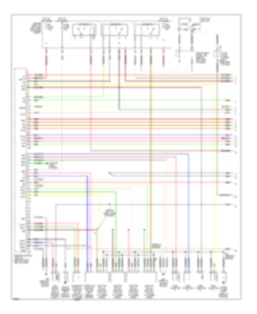
1.5L
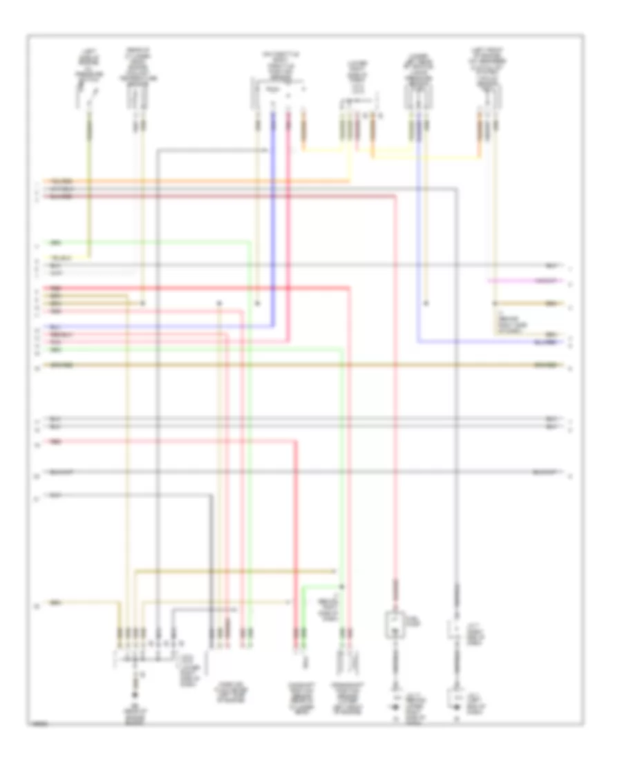
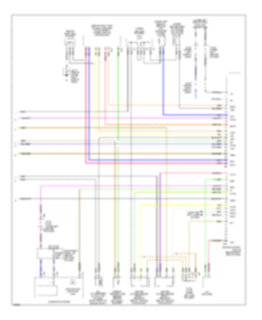
1.5L, Engine Controls Wiring Diagram (1 of 3) for Toyota Prius 2003
List of elements for 1.5L, Engine Controls Wiring Diagram (1 of 3) for Toyota Prius 2003:
- #10
- #20
- #30
- #40
- (rear of engine)
- +bm
- A10
- Acc
- Am2 fuse 15a
- Batt
- Camshaft timing oil control valve (front of cylinder head)
- Cir relay
- Cooling fans system
- E01
- E02
- E03
- E4 (rear of engine)
- Ea (rear of engine block)
- Eb (rear of engine block)
- Efi fuse 15a
- Efi relay
- Engine control module (behind right end of dash)
- Engine room j/b (left side of engine compt)
- Evg
- Evp1
- F12
- F13
- Fan
- Fuel injector
- G11
- Ge01
- Hot at all times
- I7 (behind right side of dash)
- Ig2 relay
- Igf
- Ignition coil & ignitor 1 (top of cylinder head)
- Ignition coil & ignitor 2 (top of cylinder head)
- Ignition coil & ignitor 3 (top of cylinder head)
- Ignition coil & ignitor 4 (top of cylinder head)
- Ignition switch
- Igt1
- Igt2
- Igt3
- Igt4
- Instrument panel j/b (behind left end of dash)
- J/c 24, j/c 25 (upper left j25 center of dash)
- J24
- Knk1
- Knock sensor (left side of engine)
- Lock
- Me01
- Mops
- Nca
- Ne+
- Ne-
- Noise filter (left rear of engine)
- Ocv+
- Ocv-
- Pnk
- Red
- Side of engine)
- Start
- Tha
- Thro fuse 15a
- Throttle control motor (left
- Thw
- Vsv (evap) (right side of engine compt)
- Vta
- Vta2
1.5L, Engine Controls Wiring Diagram (2 of 3) for Toyota Prius 2003
List of elements for 1.5L, Engine Controls Wiring Diagram (2 of 3) for Toyota Prius 2003:
- (left front of engine) (hc absorber & catalyst system) vacuum sensor
- (left side of engine) oil pressure switch
- (lower right side of dash) j/c 8, j/c 9
- (on throttle body) throttle position sensor
- (rear of cylinder head) engine coolant temperature sensor
- (under left rear of vehicle) vapor pressure sensor
- Camshaft position sensor (rear of cylinder head)
- Crankshaft position sensor (lower left front of engine)
- Eb (rear of engine block)
- Fuel pump
- I7 (behind right side of dash)
- J/c 1 (left end of dash)
- J/c 17 (behind upper right side of dash)
- J/c 7 (right end of dash)
- J/c 8, j/c 9 (lower right side of dash)
- Mass air flow meter (left side of engine)
- Nca
- Pnk
- Red
1.5L, Engine Controls Wiring Diagram (3 of 3) for Toyota Prius 2003
List of elements for 1.5L, Engine Controls Wiring Diagram (3 of 3) for Toyota Prius 2003:
- (behind right end of dash) j/c 18
- (behind right side of dash, forward of glove box) hybrid vehicle control ecu
- (lower left side of dash) data link connector 3
- (under center rear of vehicle) vsv (purge switching valve)
- (under left rear of vehicle) vsv (canister closed valve)
- (upper
- A/c amplifier
- Act
- Ambient temperature sensor (behind
- C10
- C11
- Ccv
- Combination meter
- Computer data lines system
- E10
- E11
- Engine control module (behind right end of dash)
- Estp
- Eth+
- Eth-
- Gauge fuse 15a
- H12
- H14
- Hcc
- Hcls
- Heated oxygen sensor (bank 1, sensor 2) (below vehicle, on exhaust)
- Hot in on or start
- Ht1a
- Ht1b
- Hte-
- Igsw
- Instrument panel j/b (behind left end of dash)
- J/c 16 (upper right side of dash)
- J/c 17 (behind upper right side of dash)
- J/c 22 (upper left side of dash)
- J/c 22, j/c 23 (upper
- J/c 26 (upper left center of dash)
- J/c 27, j/c 28 (upper left center j27 of dash)
- J22
- J23
- J28
- Left end of dash) j/c 4, j/c 5
- Left front bumper)
- Left side of dash)
- Malfunction indicator lamp
- Mpx1
- Mpx2
- Mrel
- Nca
- Neo
- Ox1a
- Ox1b
- Pnk
- Ptnk
- Sil
- Spd
- Sphv
- Tam
- Tbp
- Vsv (hc absorber & catalyst system (right front of engine compt)

 Čeština
 Dansk
Dansk Deutsch
 Ελληνικά
 English
 English
 Español
 Suomi
Suomi Français
 Français
 עברית
עברית Hrvatski
 Magyar
 日本語
日本語 한국어
한국어 Nederlands
 Polski
 Português
 Português
 Română
 Русский
 Slovenčina
 Slovenščina
 Svenska
 Türkçe
 中文 (中国)