Čeština
 Dansk
Dansk Deutsch
 Ελληνικά
 English
 English
 Español
 Suomi
Suomi Français
 Français
 עברית
עברית Hrvatski
 Magyar
 日本語
日本語 한국어
한국어 Nederlands
 Polski
 Português
 Português
 Română
 Русский
 Slovenčina
 Slovenščina
 Svenska
 Türkçe
 中文 (中国)

2005 GENERAL MOTORS Hummer H2
Hummer H2 2005 - BUZZERS, RELAYS & TIMERS
Hummer H2 2005 BUZZERS, RELAYS & TIMERS LOCATION
Component Location FUEL PMP RELAY In underhood fuse block. HDLP HIGH RELAY In underhood fuse block. HDLP LOW RELAY In underhood fuse block. HORN RELAY In underhood fuse block. IGN 1 RELAY (GAS) In underhood fuse block. Liftgate Relay (Except SUT) At base of right "B" pillar. See Fig. 68 . LOCK RELAY In I/P fuse block. See Fig. 26 . PARK LP RELAY In underhood fuse block. REAR DEFOG RELAY In I/P relay block. See Fig. 27 . STARTER RELAY In underhood fuse block. Sun Roof Relay Attached to headliner harness, near left side of dash. See Fig. 76 . UNLOCK RELAY In I/P fuse block. See Fig. 26 . W/S WASH RELAY In underhood fuse block.
Hummer H2 2005 - CIRCUIT PROTECTION DEVICES
Hummer H2 2005 CIRCUIT PROTECTION DEVICES LOCATION
Component Location Body Relay Block Near parking brake assembly. See Fig. 40 . I/P Fuse Block I/P On lower left side of dash. See Fig. 2 . I/P Junction Block On lower right side of dash. See Fig. 4 . I/P Relay Block On left side of dash, near left kick panel. See Fig. 3 . Rear Junction Block On underside of rear body, near center of rear bumper. Steering Column Fuse Holder In steering column harness, near base of steering column. Underhood Fuse Block At left side of engine compartment, near battery. See Fig. 1 .
Hummer H2 2005 - CONTROL UNITS
Hummer H2 2005 CONTROL UNITS LOCATION
Component Location Air Suspension Module (ZM6) Near right front of compressor. Blower Motor Control Processor Behind right side of dash, on HVAC assembly. See Fig. 31 . Body Control Module (BCM) On top left side of dash, above I/P fuse block. See Fig. 15 . Driver Door Module (DDM) Behind driver's door panel. See Fig. 65 . Electronic Brake Control Module (ECBM) On left side of inner frame. See Fig. 41 . Heated Seat Control Module-LR Under left side of 2nd row seat. See Fig. 100 . Heated Seat Control Module-RR Under right side of 2nd row seat. See Fig. 100 . HVAC Control Module Center of dash. See Fig. 101 . HVAC Module On HVAC assembly. See Fig. 31 . Inflatable Restraint I/P Module Behind right side of dash. See Fig. 101 . Inflatable Restraint I/P Module Connector Behind right side of dash. See Fig. 56 . Inflatable Restraint Sensing & Diagnostic Module (SDM) Under left front seat. See Fig. 56 . Inflatable Restraint Sensing & Diagnostic Module (SDM) Connector Under left front seat. See Fig. 18 . Inflatable Restraint Steering Wheel Module Under horn pad. See Fig. 56 . Memory Seat Module Under driver seat. See Fig. 77 . Midgate Control Module (SUT) Center of midgate assembly, attached to window regulator assembly. Passenger Door Module (PDM) In passenger door. See Fig. 66 . Powertrain Control Module (PCM) On left front of engine compartment. See Fig. 47 . Rear Window Wiper/Washer Module (Except SUT) At center of liftgate. See Fig. 69 . RSA Controller At rear of center console. See Fig. 6 . Sunroof Module In front of headliner, near front overhead console. See Fig. 75 . Theft Deterrent Control Module In steering column. Throttle Actuator Control (TAC) Module At left rear of engine compartment. See Fig. 47 . Transfer Case Shift Control Module Behind headlamp switch. See Fig. 8 . Vehicle Communication Interface Module (UE9) At center of dash, below HVAC control module. See Fig. 61 . Windshield Wiper/Washer Module Under windshield cowl, between wiper arms. See Fig. 81 .
Hummer H2 2005 - MOTORS
Hummer H2 2005 MOTORS LOCATION
Component Location Air Suspension Compressor Center rear of vehicle, rear of trailer hitch. See Fig. 96 . Air Temperature Actuator - Left) Attached to lower middle underside of HVAC assembly, below evaporator. See Fig. 31 . Air Temperature Actuator - Right At middle top of HVAC assembly, above evaporator. See Fig. 31 . Blower Motor At right lower side of dash, on HVAC assembly. Encoder Motor At rear of transfer case. See Fig. 37 . Fuel Pump & Sender Assembly In fuel tank. See Fig. 49 . Mode Actuator On left side of HVAC assembly. See Fig. 31 . Rear Window Wiper Motor At center of liftgate. See Fig. 81 . Recirculation Actuator On top front of HVAC assembly. See Fig. 31 . Seat Bolster Motor-Driver In driver seat back. See Fig. 55 . Seat Bolster Motor-Passenger In passenger seat back. See Fig. 79 . Seat Front Vertical Motor-Driver Under driver seat. See Fig. 102 . Seat Front Vertical Motor-Front Passenger Under front passenger seat. See Fig. 103 . Seat Horizontal Motor-Driver Under driver seat. See Fig. 102 . Seat Horizontal Motor-Front Passenger Under front passenger seat. See Fig. 103 . Seat Lumbar Motor-Driver In driver seat back. See Fig. 55 . Seat Lumbar Motor-Passenger In passenger seat back. See Fig. 79 . Seat Rear Vertical Motor-Driver Under driver seat. See Fig. 102 . Seat Rear Vertical Motor-Front Passenger Under front passenger seat. See Fig. 103 . Seat Recline Motor-Driver Under driver seat. See Fig. 102 . Seat Recline Motor-Front Passenger Under front passenger seat. See Fig. 103 . Starter At lower right side of engine. See Fig. 105 . Throttle Actuator Control Assembly Mounted to throttle body assembly, on top of engine. Throttle Actuator Control Motor Mounted to throttle body assembly, on top of engine. Transfer Case Encoder Motor At left rear of transfer case assembly. See Fig. 38 . Window Motor - Driver In driver door. See Fig. 65 . Window Motor - Front Passenger In front passenger door. See Fig. 66 . Window Motor-LR In left rear door. See Fig. 67 . Window Motor-RR In the right rear door. See Fig. 95 . Windshield Washer Fluid Pump - Reversible In washer fluid reservoir. See Fig. 81 . Windshield Wiper Motor And Module At center rear of engine compartment. See Fig. 81 .
Hummer H2 2005 - SENDING UNITS & SENSORS
Hummer H2 2005 SENDING UNITS & SENSORS LOCATION
Component Location A/C Refrigerant Pressure Sensor In rear of A/C compressor. Air Suspension Pressure Sensor (ZM6) At right side of compressor head. Air Suspension Sensor - LR (ZM6) At left rear frame rail, attached to top of frame. See Fig. 34 . Air Suspension Sensor - RR (ZM6) At right rear frame rail, attached to top of frame. Air Temperature Sensor Connector - Lower Left On left side of HVAC assembly. See Fig. 31 . Air Temperature Sensor Connector - Lower Right On left side of HVAC assembly. See Fig. 31 . Air Temperature Sensor Connector - Upper Right At right side of dash panel. See Fig. 30 . Air Temperature Sensor - Upper Left At left side of dash panel. See Fig. 30 . Air Temperature Sensor - Upper Right At right side of dash panel. See Fig. 30 . Ambient Air Temperature Sensor Assembly-HVAC At middle left side of headliner, above driver's seat. See Fig. 60 . Ambient Air Temperature Sensor - HVAC At right front of vehicle, to right of radiator support. See Fig. 30 . Ambient Air Temperature Sensor - Mirror At right front of vehicle, to right of radiator support. See Fig. 30 . Ambient Light/Sunload Sensor Assembly On top center of dash. See Fig. 30 . APP Sensor Below left side of dash. See Fig. 44 . APP Sensor Connector At APP sensor. See Fig. 44 . Camshaft Position (CMP) Sensor Connector At top center rear of engine, near engine oil pressure sensor. See Fig. 10 . Crankshaft Position (CKP) Sensor At lower right rear side of engine block, behind starter solenoid. See Fig. 46 . Crankshaft Position (CKP) Sensor Connector At sensor. See Fig. 72 . Engine Coolant Temperature (ECT) Sensor Near rear of engine block, below exhaust manifold. See Fig. 45 . Engine Oil Pressure (EOP) Sensor Connector At left rear of engine. See Fig. 10 . Fuel Level Sensor At top of fuel tank. See Fig. 74 . Fuel Tank Pressure (FTP) Sensor On fuel tank, integral to fuel pump & sender assembly. See Fig. 49 . Heated Oxygen Sensor (HO2S)-Bank 1 Sensor 1 In left exhaust pipe, before catalytic converter. See Fig. 49 . Heated Oxygen Sensor (HO2S)-Bank 1 Sensor 2 In left exhaust pipe, after catalytic converter. See Fig. 49 . Heated Oxygen Sensor (HO2S)-Bank 2 Sensor 1 In right exhaust pipe, before catalytic converter. See Fig. 49 . Heated Oxygen Sensor (HO2S)-Bank 2 Sensor 2 In right exhaust pipe, after catalytic converter. See Fig. 49 . Inflatable Restraint Electronic Frontal Sensor (EFS) (2) At front left/right of engine compartment. See Fig. 58 . Inflatable Restraint Front End Sensor - Left On left front of vehicle, by core support. See Fig. 56 . Inflatable Restraint Front End Sensor - Right On right front of vehicle, by core support. See Fig. 57 . Intake Air Temperature (IAT)/Mass Airflow (MAF) Sensor In air induction tube. See Fig. 28 . Knock Sensor (KS) 1 In valley, under intake manifold. See Fig. 50 . Knock Sensor (KS) 2 In valley, under intake manifold. See Fig. 50 . Knock Sensor Pigtail At top of engine. See Fig. 48 . Manifold Absolute Pressure (MAP) Sensor On top rear of engine, on intake manifold. See Fig. 48 . Passlock Sensor Part of ignition lock cylinder, in steering column assembly. See Fig. 43 . Seat Front Vertical Position Sensor - Driver Under the driver's seat. Seat Front Vertical Position Sensor - Passenger Under the passenger seat. Vehicle Speed Sensor (VSS) On rear of transfer case assembly. See Fig. 52 . VSS Sensor At rear of transfer case. See Fig. 54 . Washer Fluid Level Sensor In washer fluid reservoir. See Fig. 81 . Wheel Speed Sensor (WSS) - LF (RF Similar) On front wheel hub assembly. See Fig. 41 . Wheel Speed Sensor (WSS) - LR (RR Similar) On rear wheel hub assembly. See Fig. 41 .
Hummer H2 2005 - SOLENOIDS & SOLENOID VALVES
Hummer H2 2005 SOLENOIDS & SOLENOID VALVES LOCATION
Component Location A/C Compressor Clutch At lower right front of engine. See Fig. 29 . A/C Compressor Clutch Connector At lower right front of engine. See Fig. 29 . Air Suspension Exhaust Valve Connector (ZM6) At air suspension exhaust valve. Air Suspension Exhaust Valve (ZM6) Attached to right side of compressor head. Air Suspension Inlet Valve Connector-LR/RR (ZM6) At air suspension inlet valve. Air Suspension Inlet Valve-Left Rear (ZM6) Near right front of compressor. Air Suspension Inlet Valve-Right Rear (ZM6) Near right front of compressor. A/T Shift Lock Control Solenoid Integral to floor shift assembly. Door Latch Assembly - Driver At rear of driver door. See Fig. 65 . Door Latch Assembly-LR (RR Similar) At rear of door. See Fig. 67 . Door Latch Assembly - Passenger At rear of passenger door. See Fig. 66 . Door Lock Actuator-Liftgate At lower center of liftgate. See Fig. 69 . Evaporative Emission Canister Vent (EVAP) Solenoid On right front side of fuel tank. See Fig. 49 . Evaporative Emissions (EVAP) Canister Purge Solenoid On top right front of engine. See Fig. 48 . Fuel Injector 1 At left side of engine. See Fig. 45 . Fuel Injector 2 At right side of engine. See Fig. 104 . Fuel Injector 3 At left side of engine. See Fig. 45 . Fuel Injector 4 At right side of engine. See Fig. 104 . Fuel Injector 5 At left side of engine. See Fig. 45 . Fuel Injector 6 At right side of engine. See Fig. 104 . Fuel Injector 7 At left side of engine. See Fig. 45 . Fuel Injector 8 At right side of engine. See Fig. 104 . Ignition Lock Cylinder Control Actuator Behind ignition switch assembly. See Fig. 62 . Ignition Lock Cylinder Control Actuator Connector At ignition lock cylinder. See Fig. 62 . Liftgate Lock Actuator In the center rear of liftgate, behind trim panel. Park Lock Solenoid Part of automatic transmission shift lever. Pressure Control (PC) Solenoid Valve In automatic transmission. See Fig. 52 . Rear Differential Lock Actuator On rear axle, at top of differential housing. See Fig. 36 . Starter Solenoid At right rear of engine. See Fig. 105 . Torque Converter Clutch Pulse Width Modulation (TCC PWM) Solenoid Valve In automatic transmission. See Fig. 52 . Torque Converter Clutch (TCC) Solenoid Valve In automatic transmission. See Fig. 52 . 1-2 Shift Solenoid (SS) Valve At rear of transmission. See Fig. 52 . 2-3 Shift Solenoid (SS) Valve At rear of transmission. See Fig. 52 . 3-2 Shift Solenoid (SS) Valve Assembly In transmission. See Fig. 52 .
Hummer H2 2005 - SWITCHES
Hummer H2 2005 SWITCHES LOCATION
Component Location A/C Low Pressure Switch On right side of accumulator. See Fig. 28 . A/C Refrigerant Pressure Switch At right front of engine. See Fig. 29 . Air Suspension Inflator Switch Connector (ZM6) At right rear frame body mount. See Fig. 23 . Air Suspension Inflator Switch (ZM6) Near right "D" pillar. See Fig. 34 . Automatic Transmission Fluid Pressure (TFP) Manual Valve Position Switch In automatic transmission. See Fig. 52 . Brake Fluid Level Switch Connector On left side of brake fluid reservoir. See Fig. 39 . Door Lock Switch - Rear Near right "D" pillar. See Fig. 34 . Engine Oil Level Switch On lower right side of oil pan. See Fig. 47 . Ignition Key Alarm Switch On ignition key cylinder. See Fig. 43 . Ignition Lock Cylinder Control Switch Part of automatic transmission shift lever. Ignition Switch On steering column. See Fig. 43 . Inflatable Restraint I/P Module Disable Switch Behind right side of dash. See Fig. 101 . Liftgate Ajar Switch-Left (Except SUT) At lower left side of liftgate. See Fig. 69 . Liftgate Ajar Switch-Right (Except SUT) At lower right side of liftgate. See Fig. 69 . Midgate Latch Release Switch-Left (SUT) On LH side of midgate trim panel, below midgate glass. Midgate Latch Release Switch-Right (SUT) On RH side of midgate trim panel, below midgate glass. Park Brake Switch Connector Part of parking brake assembly. See Fig. 40 . PNP Switch On left side of transmission. See Fig. 53 . Seat Belt Switch Connector At right side of driver seat. See Fig. 55 . Stop Lamp Switch On top of brake pedal bracket. See Fig. 51 .
Hummer H2 2005 - MISCELLANEOUS
Hummer H2 2005 MISCELLANEOUS LOCATION
Component Location Accessory Power Outlet-LR (Console) At rear of center console. See Fig. 6 . Accessory Power Outlet-RR (Console) At rear of center console. See Fig. 6 . Accessory Power Outlet-RR (Rear Cargo Storage Bin) At rear of rear cargo storage bin. See Fig. 7 . Accessory Power Outlet (2) At center of dash. See Fig. 5 . Audio Amplifier Under front floor console, between front seats. See Fig. 63 . Battery At left side of engine compartment. See Fig. 58 . Cell Phone/GPS Antenna At left front of roof. See Fig. 59 . Cellular Microphone LF headliner, driver side. See Fig. 60 . Cellular & Navigation Antenna At top left front of roof. See Fig. 99 . Data Link Connector (DLC) Under left side of dash, below steering column. See Fig. 15 . Digital Radio Antenna LF corner of roof panel, near luggage roof rail. Digital Radio Receiver Behind the glove box. See Fig. 101 . Electric Locking Differential Case Assembly Integral to lock differential. See Fig. 35 . Generator At top left of engine. See Fig. 105 . Global Positioning System (GPS) Antenna (I/P) On dash. See Fig. 99 . Heated Seat Element Connector-LR Under left side of 2nd row seat. See Fig. 80 . Heated Seat Element Connector-RR Under right side of 2nd row seat. See Fig. 80 . Heated Seat Element-Driver Cushion In driver seat. See Fig. 55 . Heated Seat Element-Driver Cushion Connector In driver seat. See Fig. 55 . Heated Seat Element - Passenger Cushion In the passenger seat cushion. Heated Seat Element-Passenger Cushion Connector (W/KA7) Under front passenger seat. See Fig. 79 . Horn Connector-Left At horn. See Fig. 70 . Horn-Left On left lower corner of radiator core support. See Fig. 70 . Horn-Right On right lower corner of radiator core support. See Fig. 70 . Ignition Coil 1 At left side of engine. See Fig. 45 . Ignition Coil 2 At right side of engine. See Fig. 104 . Ignition Coil 3 At left side of engine. See Fig. 45 . Ignition Coil 4 At right side of engine. See Fig. 104 . Ignition Coil 5 At left side of engine. See Fig. 45 . Ignition Coil 6 At right side of engine. See Fig. 104 . Ignition Coil 7 At left side of engine. See Fig. 45 . Ignition Coil 8 At right side of engine. See Fig. 104 . Inflatable Restraint Steering Wheel Module Coil On steering column, behind steering wheel. Junction Block - Battery Cable At left side of engine. See Fig. 42 . Locking Differential Coil Assembly Integral to lock differential. See Fig. 35 . Longnitudinal Accelerometer Behind center of dash. See Fig. 41 . Midgate Latch-Left (SUT) LH side of midgate, at latch assembly. Midgate Latch-Right (SUT) RH side of midgate, at latch assembly. Navigation Radio Antenna (UM8) Behind right side of dash. See Fig. 63 . Parking Brake Assembly Under left side of dash. See Fig. 40 . Radio Center of dash. See Fig. 101 . Radio Antenna At right front of vehicle. See Fig. 99 . RCDLR (Part Of The Front Passenger Door Module) In front passenger door module. See Fig. 64 . SIR Coil At top of steering column. See Fig. 32 . Starter At right rear of engine. See Fig. 42 . Stud #1 On underhood fuse block. See Fig. 1 . Stud #2-Trailer Connector Power Feed On underhood fuse block. See Fig. 1 . Theft Deterrent Control Module Electric Park Lock In steering column. See Fig. 33 . Throttle Body Assembly Top of engine, mounted to front of intake manifold. See Fig. 104 . Trailer Receptacle At rear bumper fascia. See Fig. 25 .
Hummer H2 2005 - CONNECTORS
Hummer H2 2005 CONNECTORS LOCATION
Component Location C100 (Black, 16 Pin) Below underhood fuse block. See Fig. 87 . C101 (Black, 10 Pin) Below underhood fuse block. See Fig. 83 . C102 (Black, 12 Pin) On rear side of underhood fuse block. See Fig. 1 . C103 (Black, 14 Pin) Attached to front side of underhood fuse block. See Fig. 90 . C103 (Black, 14 Pin) Attached to front side of underhood fuse block. See Fig. 90 . C104 (Black, 12 Pin) Near underhood fuse block. See Fig. 83 . C105 (Black, 1 Pin) Near wheelwell. See Fig. 83 . C106 (Blue, 12 Pin) Below underhood fuse block. See Fig. 83 . C115 (Black, 2 Pin) At top left rear of engine, in engine harness. See Fig. 48 . C148 (Light Gray, 8 Pin) In engine harness to odd ignition coil harness. See Fig. 45 . C158 (Light Gray, 8 Pin) In engine harness to odd ignition coil harness. See Fig. 104 . C175 (Gray, 20 Pin) At right side of automatic transmission. See Fig. 86 . C200 (Black, 16 Pin) Behind left side of dash. See Fig. 13 . C201 (Yellow, 4 Pin) On left side of dash, behind left kick panel. See Fig. 13 . C202 (Black, 52 Pin) Attached to transfer case shift control bracket. See Fig. 98 . C203 (Yellow, 2 Pin) Below steering column. See Fig. 98 . C210 (Black, 12 Pin) At bottom left side of dash. See Fig. 73 . C277 (Black, 8 Pin) In top of steering column. C298 (Light Gray, 22 Pin) Behind right kick panel. See Fig. 85 . C300 (8 Pin) Left side of midgate. C310 (Black, 17 Pin) At left side "B" pillar. See Fig. 67 . C311 (Black, 3 Pin) At base of left roof rail, above driver. C320 (Black, 6 Pin) Under left rear seat. See Fig. 100 . C325 (Black, 16 Pin) Under driver's seat. See Fig. 102 . C326 (Light Gray, 13 Pin) In driver's seat harness, under driver's seat. See Fig. 102 . C327 (Light Blue, 24 Pin) In driver's seat harness, under driver's seat. See Fig. 102 . C328 (White, 10 Pin) In driver's seat harness, under driver's seat. See Fig. 102 . C329 (Black 6 Pin) In driver's seat harness, under driver's seat. See Fig. 102 . C330 (Gray, 6 Pin) In driver's seat harness, under driver's seat. See Fig. 102 . C333 (Black, 8 Pin) In driver's seat harness, under driver's seat. See Fig. 55 . C350 (Light Gray, 22 Pin) Under front floor console. See Fig. 91 . C350 (Light Gray, 22 Pin) Under front floor console. See Fig. 91 . C355 (Black, 8 Pin) At front of audio amplifier. C375 (Black, 16 Pin) Under passenger seat. See Fig. 78 . C376 (Black, 6 Pin) Under passenger seat. See Fig. 78 . C377 (Gray, 6 Pin) Under passenger seat. See Fig. 79 . C378 (Black, 4 Pin) Under passenger seat. See Fig. 79 . C380 (Black, 6 Pin) Under right rear seat. See Fig. 100 . C390 (White, 17 Pin) At right side "B" pillar. C400 (8 Pin) Right rear corner of frame, near right rear body mount. C401 (2 Pin) Right rear corner of frame, near right rear body mount. C402 (2 Pin) Right rear corner of frame, near right rear body mount. C420 (Medium Gray, 12 Pin) At top left area of liftgate. See Fig. 94 . C450 (Black, 2 Pin) At rear underside of vehicle, attached to air suspension assembly. See Fig. 96 . C451 (Black, 16 Pin) At rear underside of vehicle, attached to air suspension assembly. See Fig. 96 . C900 (Black, 12 Pin) Inside top left body opening of liftgate. See Fig. 92 .
Hummer H2 2005 - GROUNDS
Hummer H2 2005 GROUNDS LOCATION
Component Location Fuel Tank Filler Ground At left rear frame body mount. See Fig. 22 . G100 At left side of engine compartment. See Fig. 105 . G100-Forward Lamp Harness On left front frame body mount. See Fig. 9 . G100-Negative Battery Cable On left front frame body mount. See Fig. 9 . G102-Engine Harness Ground At left front side of engine block. See Fig. 11 . G102-Negative Battery Cable At left front side of engine block. See Fig. 11 . G103 At top right rear of engine. See Fig. 48 . G103-Engine Harness Ground At top right rear of engine. See Fig. 10 . G104 At top left rear of engine. See Fig. 10 . G105-Engine Harness Ground At lower left side of engine. See Fig. 71 . G105-Negative Battery Cable At lower left side of engine. See Fig. 71 . G106 At right rear of engine compartment, on forward dash panel. See Fig. 12 . G200 On left side of dash, near left kick panel. See Fig. 13 . G203 At lower right side of dash, near right kick panel. See Fig. 14 . G300 On left side body mount, in front of driver door. See Fig. 97 . G302 At left inner center "B" pillar. See Fig. 17 . G304 Under passenger seat. See Fig. 18 . G306 At right inner center "B" pillar. See Fig. 19 . G308 At right frame body mount, near right rear door. See Fig. 20 . G310 At left body mount. See Fig. 21 . G320 Left side of midgate. G401 At left rear frame body mount. See Fig. 22 . G402 Attached to front of air suspension mounting bracket. See Fig. 84 . G403 At right frame body mount, near right rear door. G405 At right rear frame body mount. See Fig. 23 . G410 On right rear inner side body panel. See Fig. 24 .
Hummer H2 2005 - SPLICES
Hummer H2 2005 SPLICES LOCATION
Component Location SP205 In I/P harness, on left side of dash, near footwell courtesy lamp. See Fig. 15 . SP206 In I/P harness, on left side of dash, near steering column in-line connector. See Fig. 8 . SP207 In body harness, on left side of dash, near left kick panel. See Fig. 16 . SP410 (Except SUT) Inside right rear cargo area, at middle of right rear "D" pillar. See Fig. 24 . S100 In forward lamp harness, 28 cm from junction of left horn harness to forward lamp harness. See Fig. 88 . S101 In forward lamp harness, 5 cm from ambient temperature sensor harness. See Fig. 89 . S102 In engine harness, 4 cm from knock sensor connector. See Fig. 87 . S103 In engine harness, 10 cm from junction of fuel injector No. 3 harness to engine harness. See Fig. 87 . S104 In engine harness, 30 cm from junction of fuel injector No. 3 harness to engine harness. See Fig. 87 . S105 (UNR) In brushguard lamp harness, 10 cm from off road lamp connector breakout. S106 (UNR) In brushguard lamp harness, 10 cm from off road lamp connector breakout. S125 In transmission wiring harness, approximately 12 cm after 1-2 shift solenoid valve breakout. S140 In ignition coil harness. S141 In ignition coil harness. S142 In ignition coil harness. S160 In ignition coil harness. S161 In ignition coil harness. S162 In ignition coil harness. S200 In dash harness, approximately 30 cm from air suspension ride height switch breakout. S201 In dash harness, approximately 24 cm from air suspension ride height switch breakout. S208 (UNR/USB/USC) In body relay harness, approximately 25 cm from dash relay block. S209 (UNR/USB/USC) In body relay harness, approximately 25 cm from dash relay block. S210 In I/P harness, 8.5 cm from junction of instrument cluster connector harness to I/P harness. S211 In I/P harness, 15 cm from junction of instrument cluster connector harness to I/P harness. S213 In I/P harness, 45.4 cm from junction of instrument cluster connector harness to I/P harness. S214 In I/P harness, 50.4 cm from junction of instrument cluster connector harness to I/P harness. S215 In I/P harness, 5.5 cm from junction of air temperature sensor. S216 In I/P harness, 2.5 cm from junction of air temperature sensor. S217 (Except SUT) In I/P harness, 25.4 cm from headlamp panel dimmer switch. S218 In steering column harness. S219 In steering column harness. S277 In steering wheel harness approximately 2.5 cm from C277. S278 In steering wheel harness approximately 2.5 cm (1 in) from C277. S290 In I/P harness, 6.5 cm from junction of I/P compartment lamp to I/P harness. S300 In headliner harness, 10 cm from junction of courtesy/reading lamp center harness to headliner harness. S301 In headliner harness, at top of left "A" pillar near corner of windshield. See Fig. 76 . S302 In headliner harness, near middle of left "A" pillar. See Fig. 76 . S303 In roof-marker harness, 22 cm from right front marker lamp connector. See Fig. 93 . S304 In chassis harness, 21.5 cm from G300. S305 In headliner harness, 5 cm from top mounting clip. See Fig. 76 . S306 In left rear seat harness. S310 In body harness, 8.5 cm from right "B" pillar courtesy lamp harness junction to body harness. S313 (USB/USC) In crossrail roof lamp harness approximately 4 cm from C311. S314 (USB/USC) In crossrail roof lamp harness approximately 10 cm from off road lamp - roof - left inner breakout. S315 (USB/USC) In crossrail roof lamp harness approximately 2 cm from C311. S326 In driver seat jumper harness, 5 cm from junction of C330 & C328. S327 In driver seat jumper harness, 10 cm from junction of C330 & C328. S328 In driver seat jumper harness, 4.5 cm from memory seat module C3. S330 (Except SUT) In body harness approximately 12 cm from C320 breakout. S331 (Except SUT) In body harness approximately 22 cm from C320 breakout. S332 (Except SUT) In body harness approximately 16.5 cm from C375 breakout. S333 (Except SUT) In body harness approximately 10 cm from C375 breakout. S334 (SUT) In midgate harness approximately 10 cm from right midgate latch breakout. S335 (SUT) In midgate harness approximately 47 cm from right midgate latch breakout. S336 (SUT) In midgate harness approximately 13 cm from left midgate latch breakout. S337 (SUT) In midgate harness approximately 13 cm from right midgate latch breakout. S338 (SUT) In midgate harness approximately 5 cm from left midgate latch breakout. S339 (SUT) In midgate harness approximately 5 cm from right midgate latch release switch breakout. S345 In roof marker harness, 16.5 cm from junction of right center roof lamp connector to roof marker harness. See Fig. 93 . S350 In console harness, 7 cm from junction of body harness in-line C355 to floor console harness. See Fig. 82 . S351 In console harness, 28.5 cm from junction of body harness in-line C355 to floor console harness. See Fig. 82 . S375 In chassis harness, 63.5 cm from rear differential lock actuator, on chassis harness. S376 In chassis harness, 63.5 cm from rear differential lock actuator, on chassis harness. S380 In passenger seat harness, 21 cm from seat adjuster switch, between lumbar bolster switch & seat adjuster switch, on right side of seat. S381 In passenger seat harness, 16 cm from lumbar bolster switch. S390 In body harness, 18.5 cm from junction of SIR module. S393 In right rear seat harness, 34 cm from heated seat module. S400 (ZM6) In chassis harness, at right rear frame rail, 15 cm from junction of right rear air suspension sensor to chassis harness. S401 (ZM6) In chassis harness, at right rear frame rail, 30 cm from junction of right rear air suspension sensor to chassis harness. S402 In chassis harness 33 cm from G405 breakout. S403 In chassis harness 39 cm from G401 breakout. S404 (SUT) In chassis harness 15 cm from G401 breakout. S405 (SUT) In chassis harness 13 cm from G405 breakout. S406 (SUT) In chassis harness 19 cm from rear differential lock actuator breakout. S407 (Except Early Production SUV) In air suspension harness at rear underside of vehicle. S408 (Except Early Production SUV) In air suspension harness at rear underside of vehicle. S409 (Except Early Production SUV) In air suspension harness at rear underside of vehicle. S410 (Except Early Production SUV) In air suspension harness at rear underside of vehicle. S411 In body harness, 15.2 cm from junction of left rear marker lamp to body harness. S412 (Except SUT) In body harness, 27.5 cm from junction of left rear side marker lamp to body harness. S413 (ZM6) (Early Production SUV) At rear underside of vehicle, in air suspension harness. S414(ZM6) At rear underside of vehicle, in air suspension harness. S480 (Except SUT) In body harness, 28 cm from junction of C420. S720 In right rear door harness, 12 cm from junction of speaker connector harness to door harness. S820 In left door harness, 11.5 cm from junction of door courtesy lamp connector harness to door harness. S900 (Except SUT) At left side of liftgate, near junction of right rear defogger connector to liftgate harness. See Fig. 69 . S901 (Except SUT) At lower right side of liftgate, 10 cm from junction of rear wiper motor connector to liftgate harness. See Fig. 69 . S902 (Except SUT) At lower right side of liftgate, 6.5 cm from right liftgate ajar switch junction to liftgate harness. See Fig. 69 .
Hummer H2 2005 - COMPONENT LOCATION GRAPHICS
NOTE:
Fig.res may show multiple component locations. - appropriate table for proper figure references.


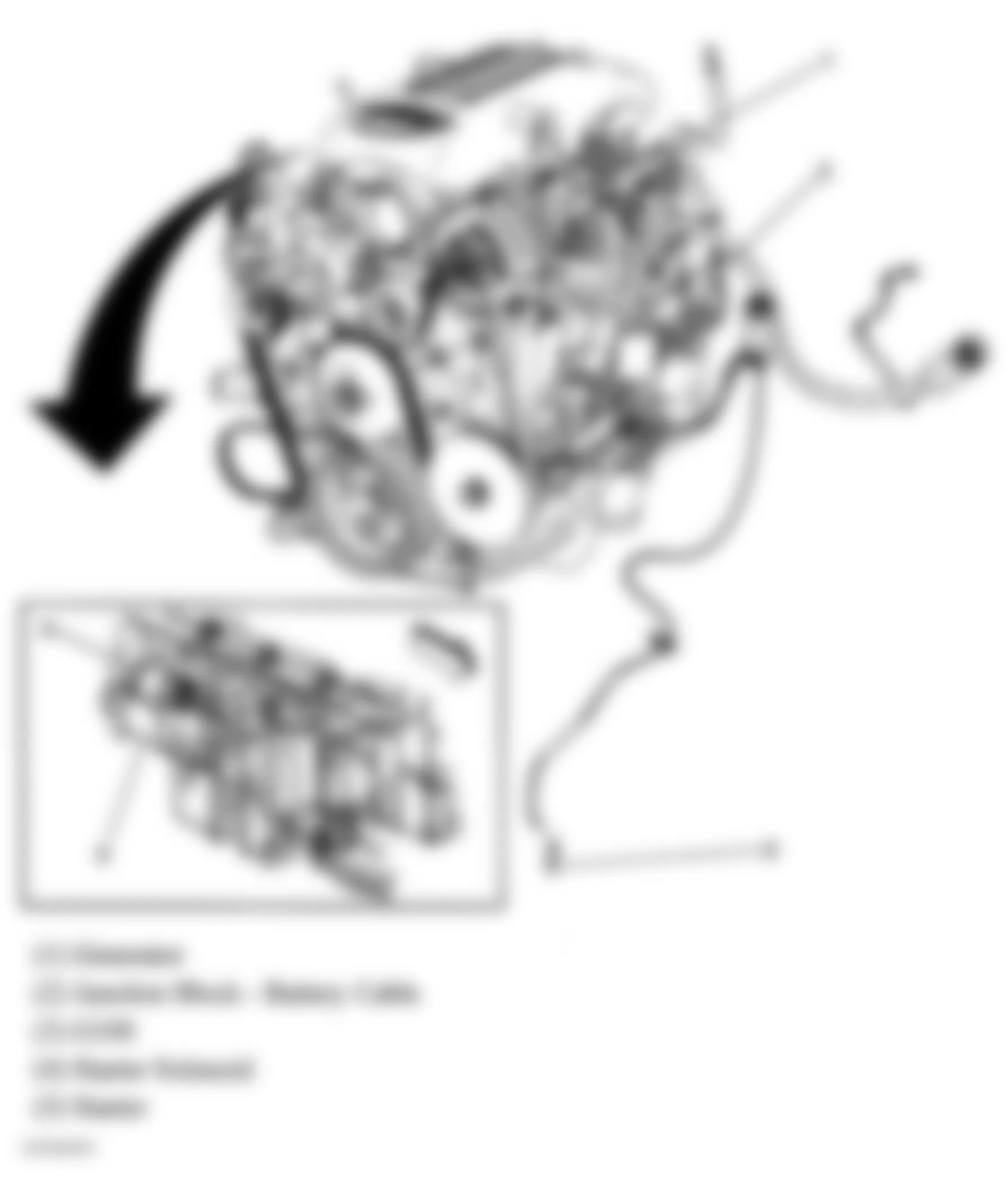
Fig. 1: Hummer H2 2005 - Component Locations - Engine Compartment
Fig. 2: Hummer H2 2005 - Component Locations - Left End Of Dash
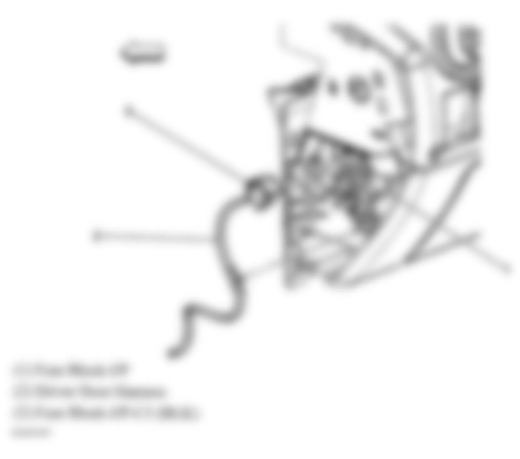
Fig. 3: Hummer H2 2005 - Component Locations - Left End Of Dash
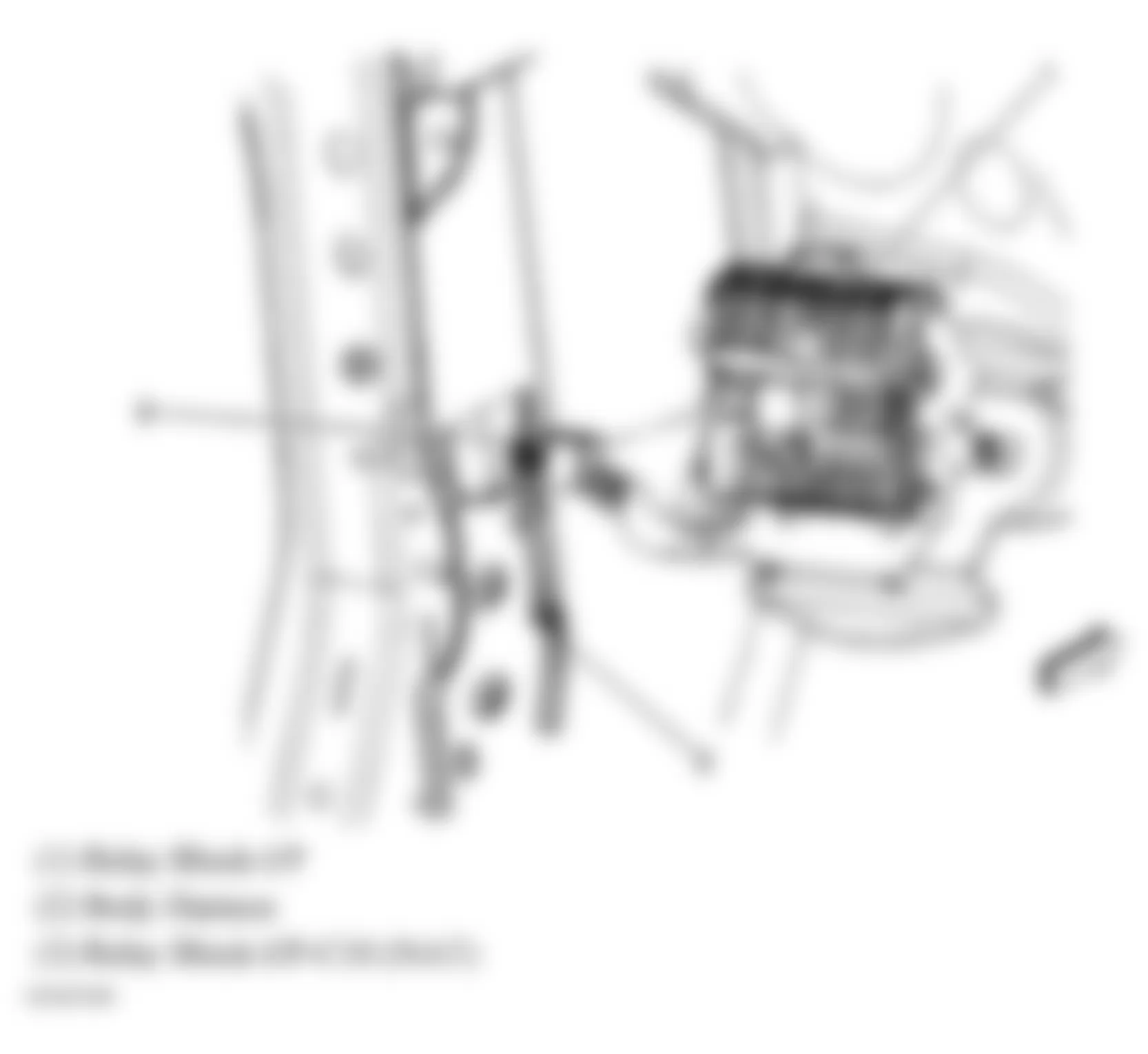
Fig. 4: Hummer H2 2005 - Component Locations - Right Side Of Dash
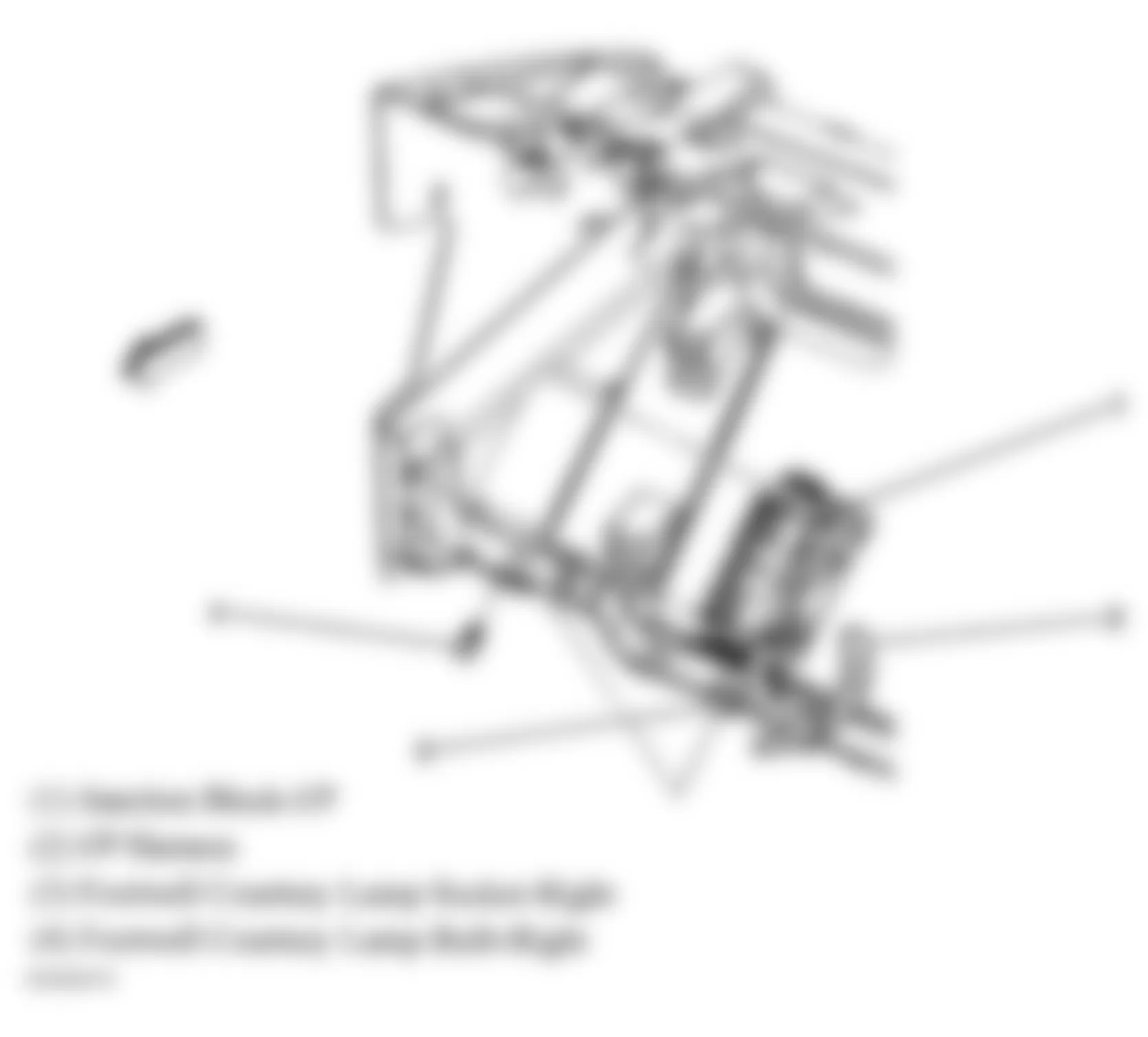
Fig. 5: Hummer H2 2005 - Component Locations - Center Of Dash
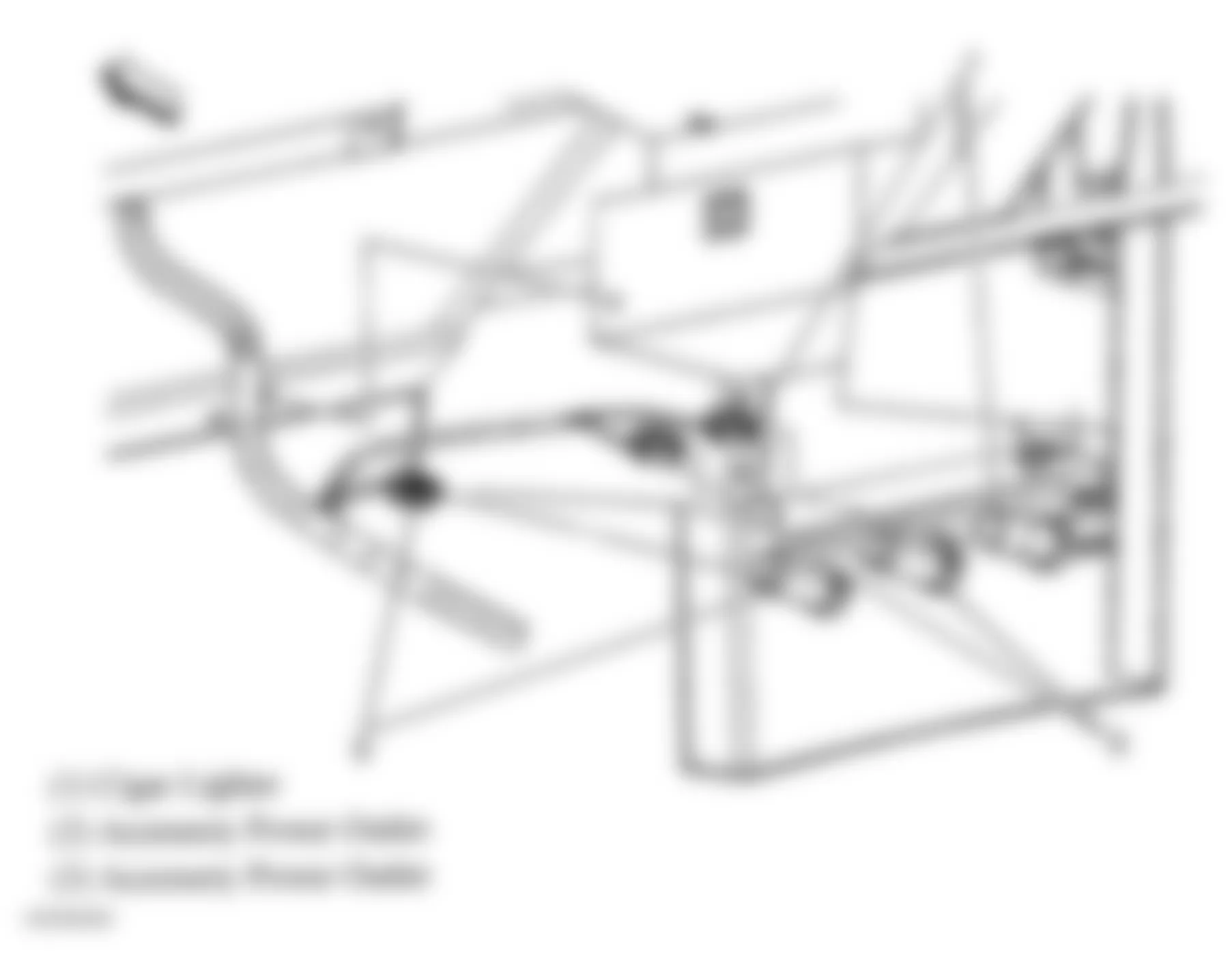
Fig. 6: Hummer H2 2005 - Component Locations - Front Floor Console
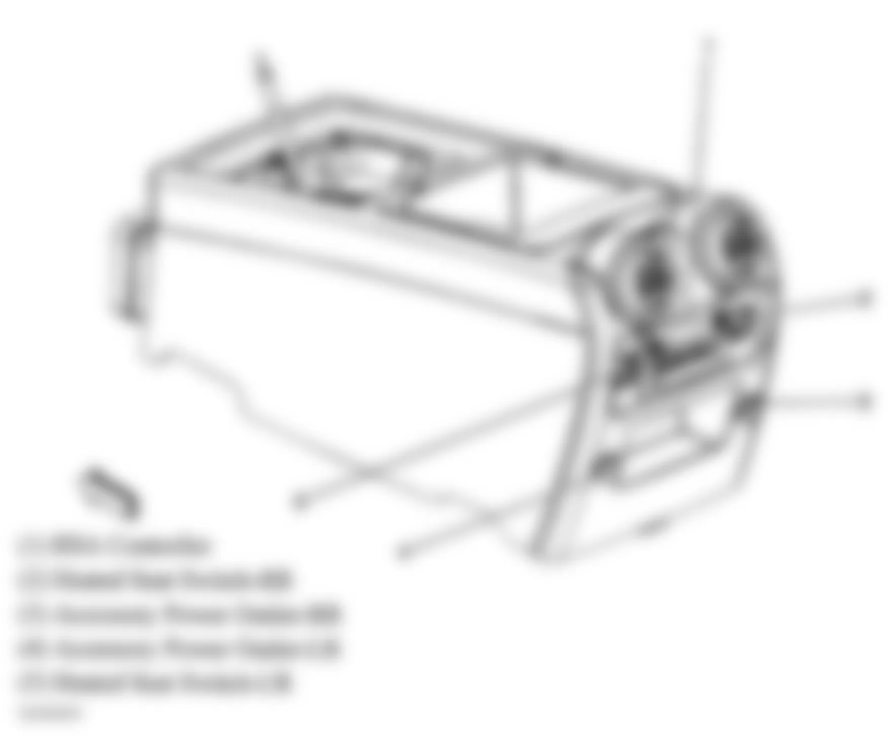
Fig. 7: Hummer H2 2005 - Component Locations - Rear Cargo Storage Bin
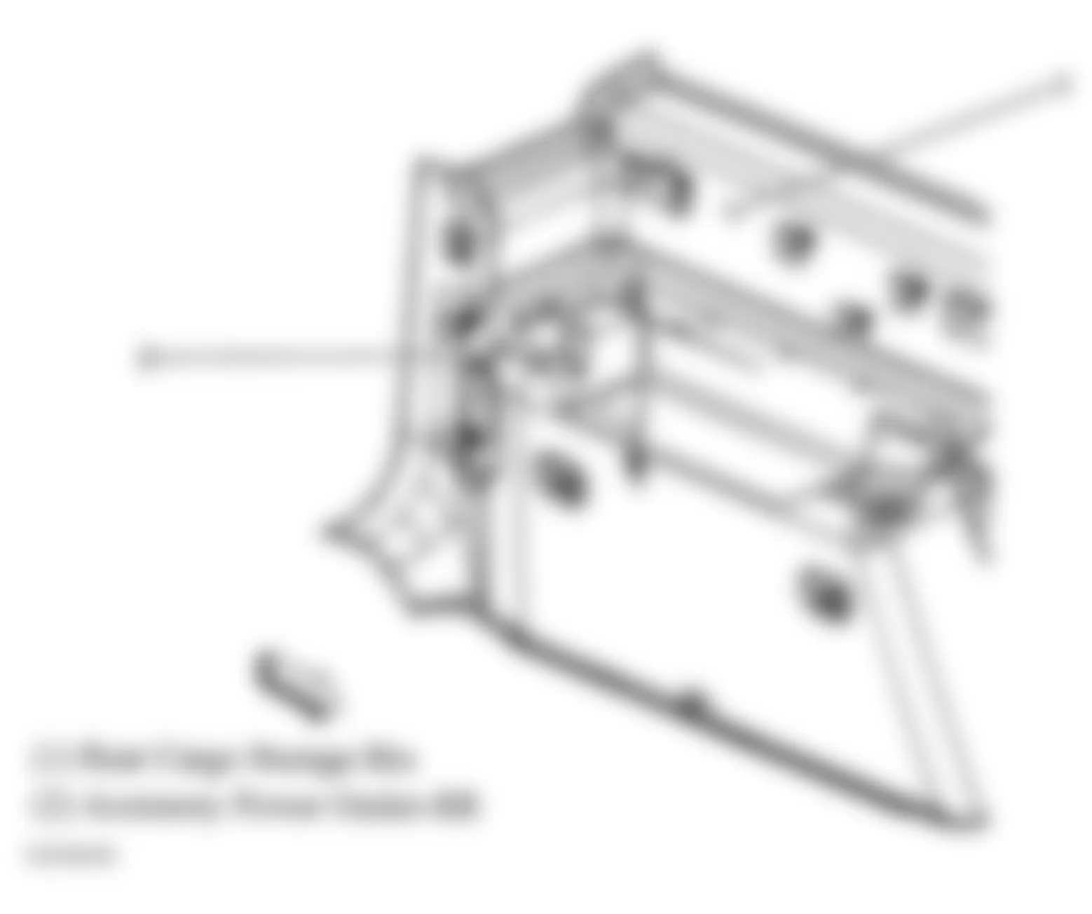
Fig. 8: Hummer H2 2005 - Component Locations - Left Side Of Dash
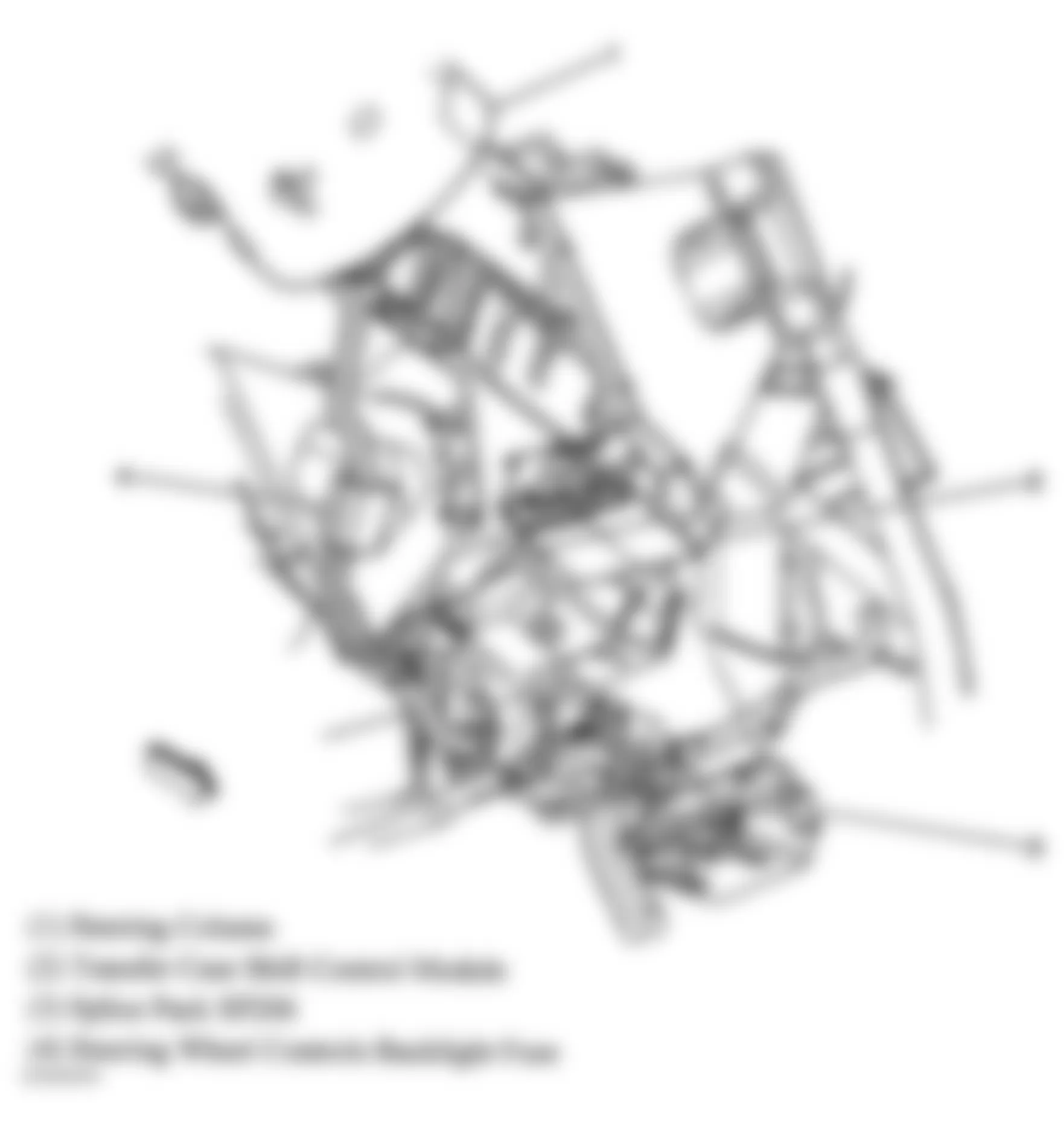
Fig. 9: Hummer H2 2005 - Component Locations - Left Front Frame Rail
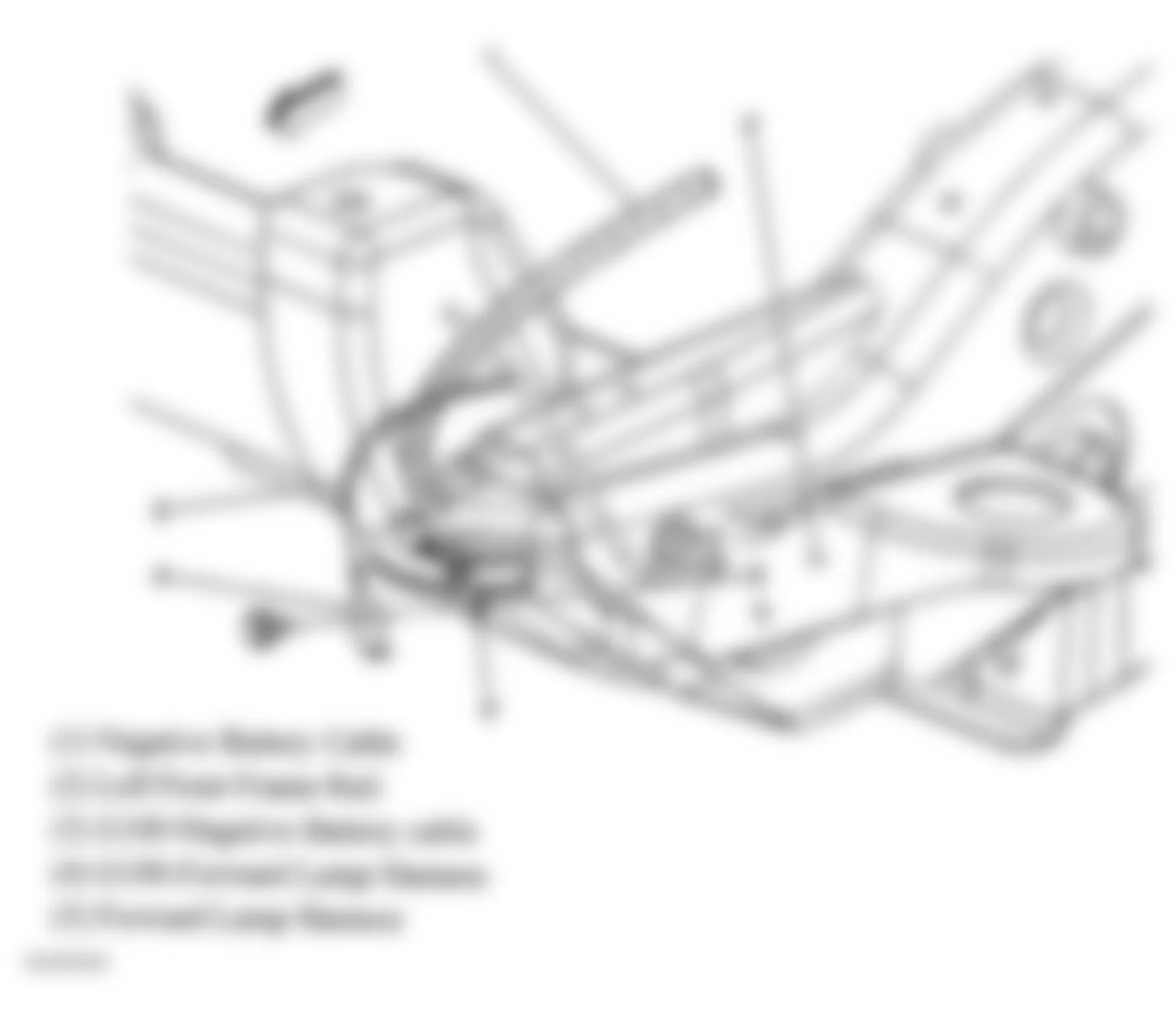
Fig. 10: Hummer H2 2005 - Component Locations - Left Rear Of Engine
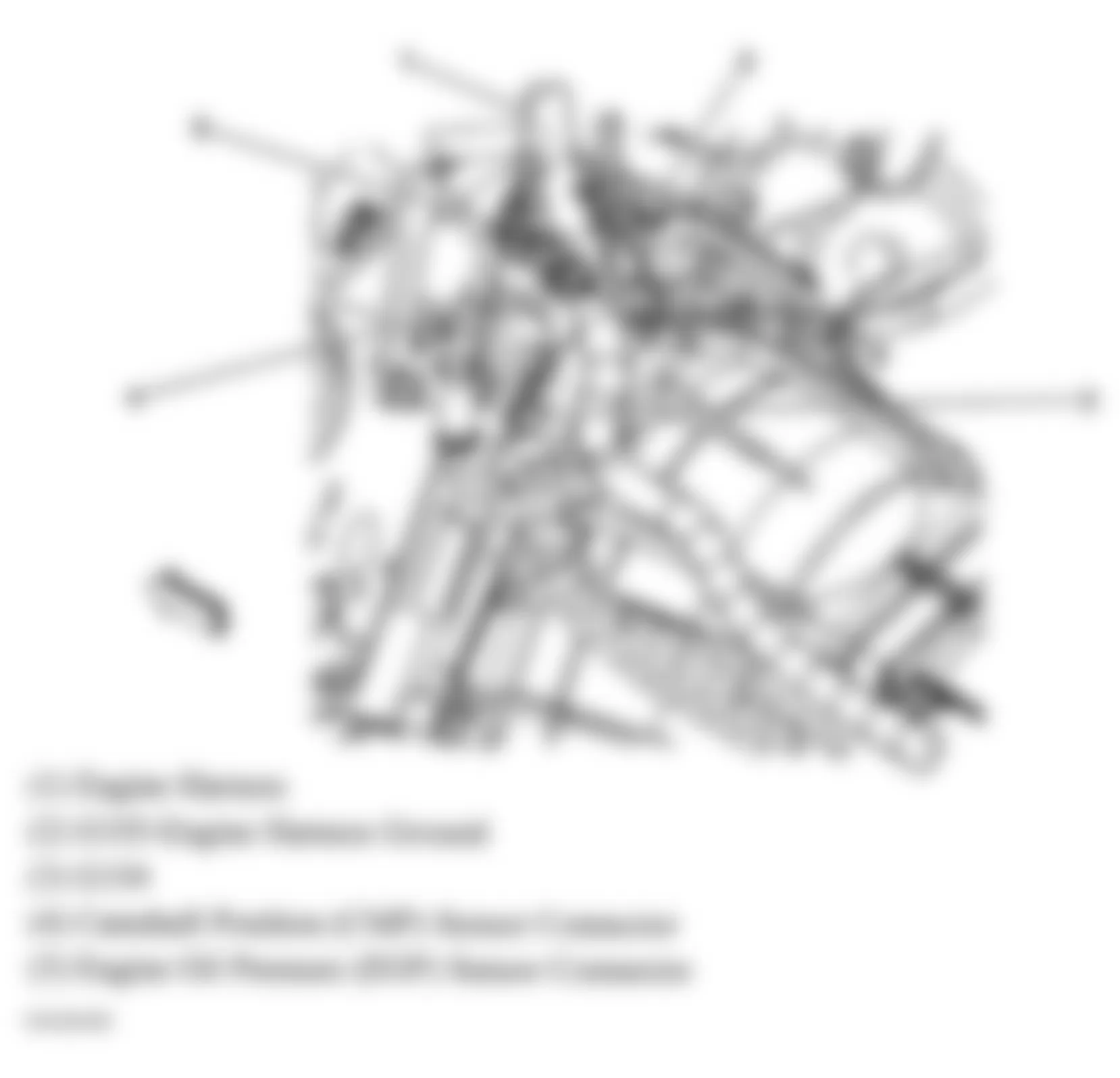
Fig. 11: Hummer H2 2005 - Component Locations - Left Side Of Engine
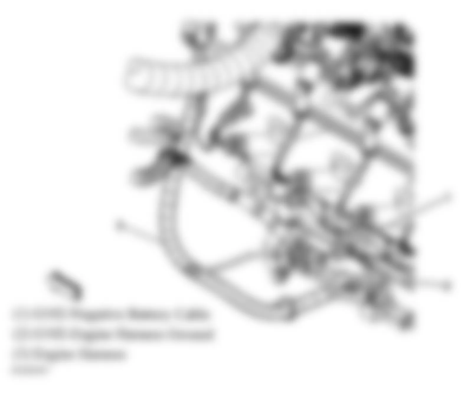
Fig. 12: Hummer H2 2005 - Component Locations - Rear Of Engine Compartment
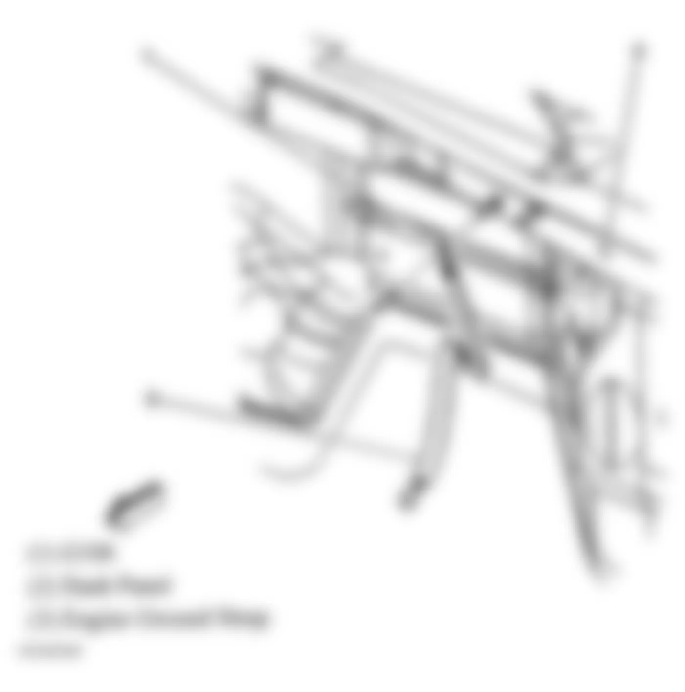
Fig. 13: Hummer H2 2005 - Component Locations - Left Kick Panel
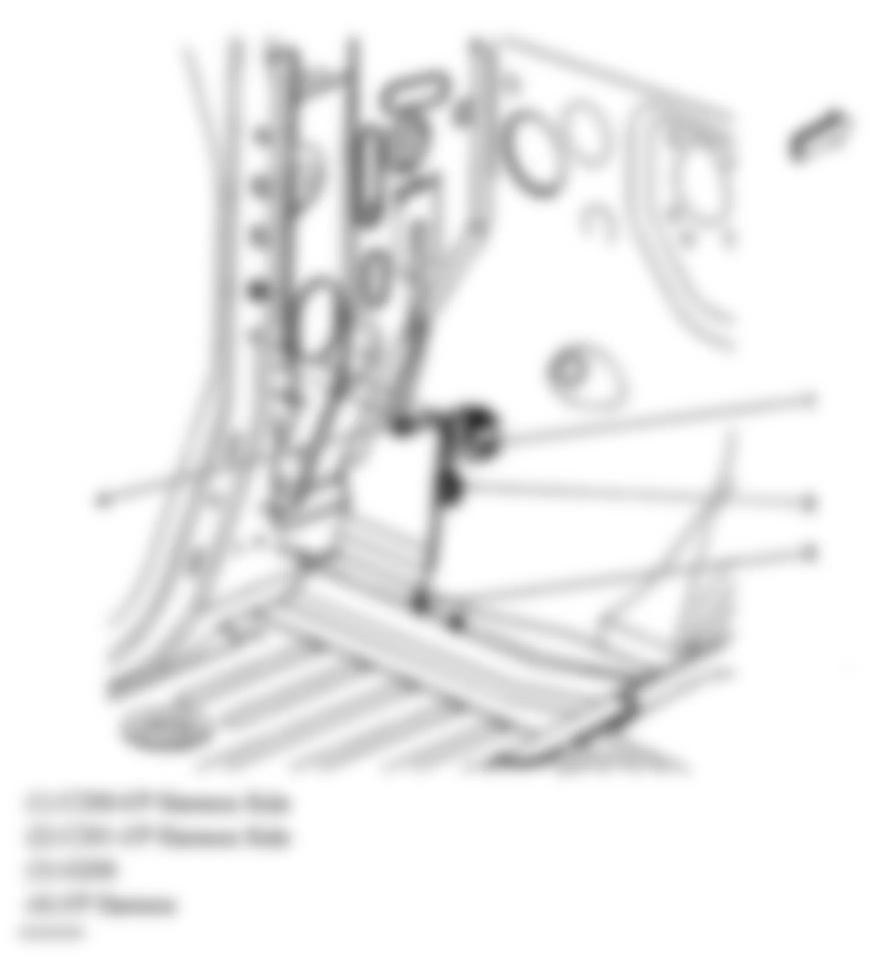
Fig. 14: Hummer H2 2005 - Component Locations - Right Kick Panel
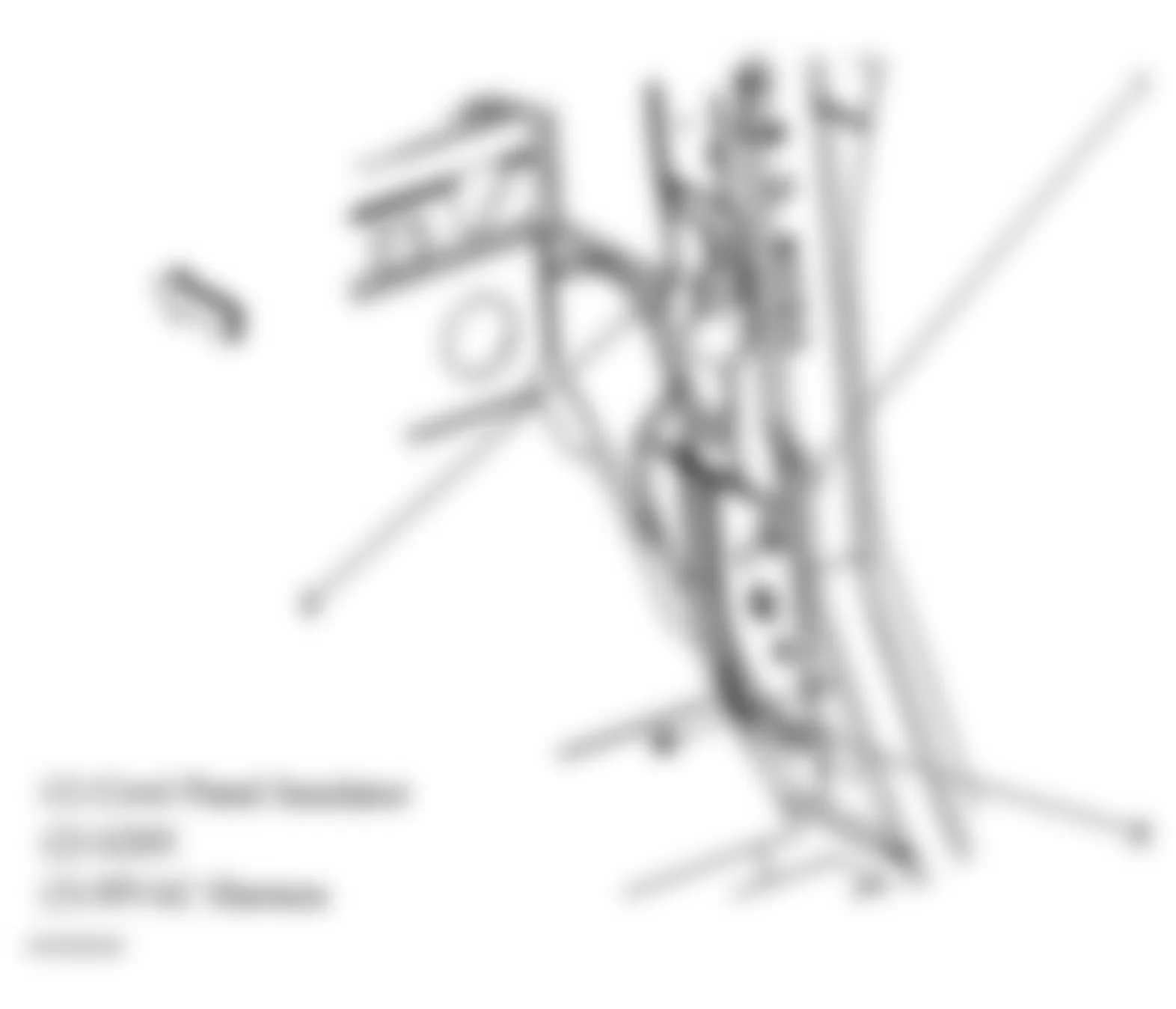
Fig. 15: Hummer H2 2005 - Component Locations - Left Side Of Dash
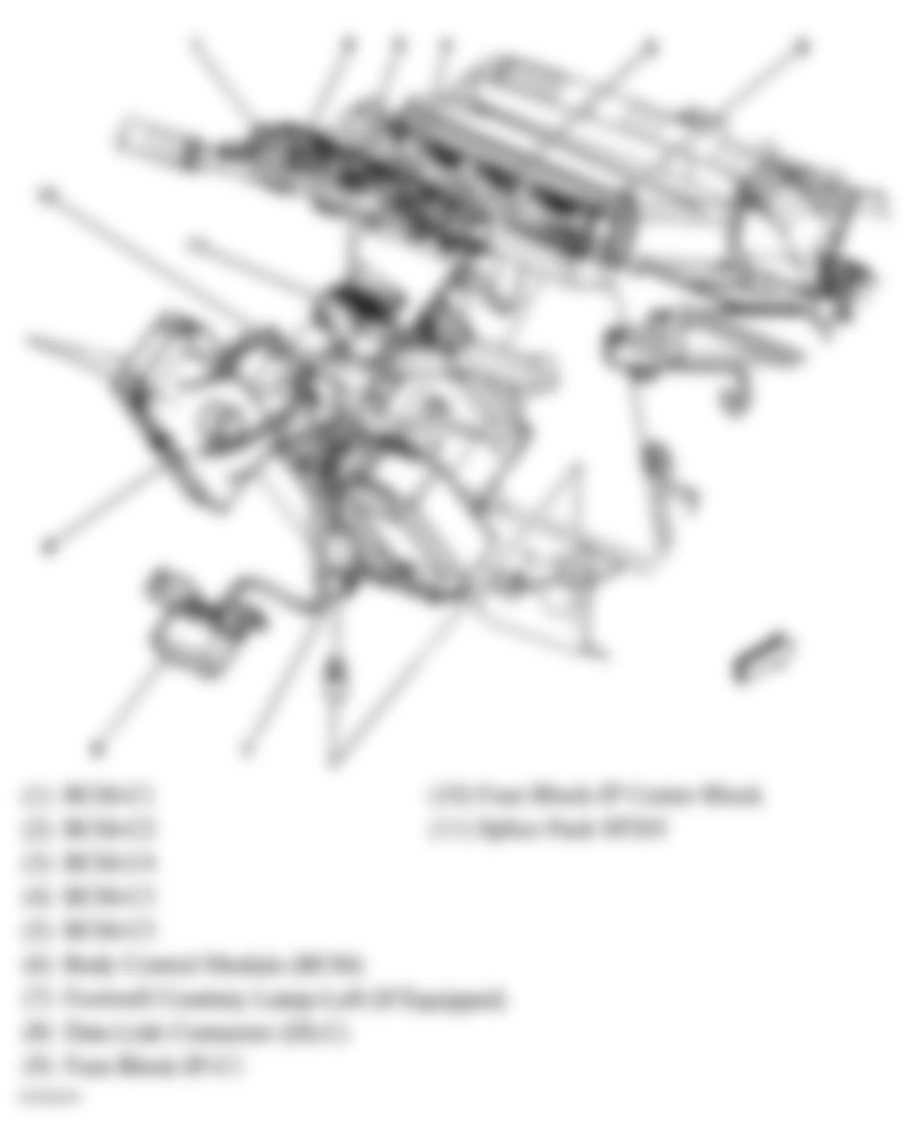
Fig. 16: Hummer H2 2005 - Component Locations - Left Kick Panel
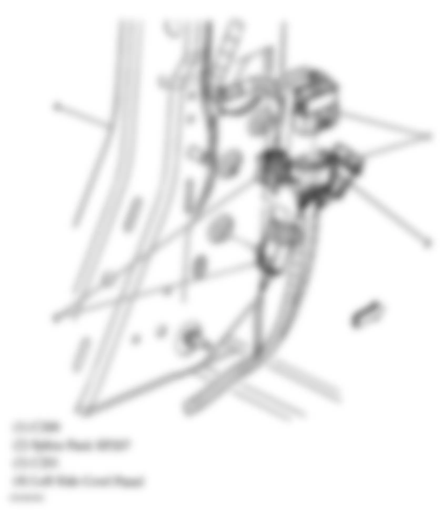
Fig. 17: Hummer H2 2005 - Component Locations - Left "B" Pillar
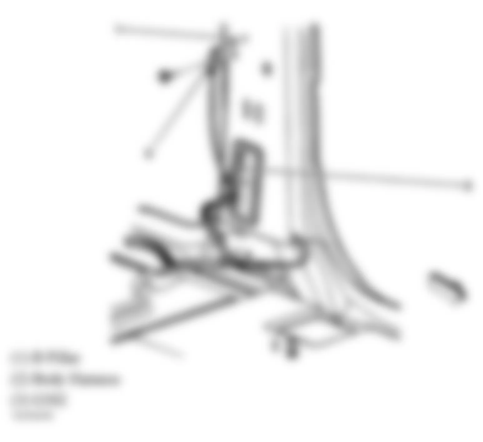
Fig. 18: Hummer H2 2005 - Component Locations - Vehicle Floor
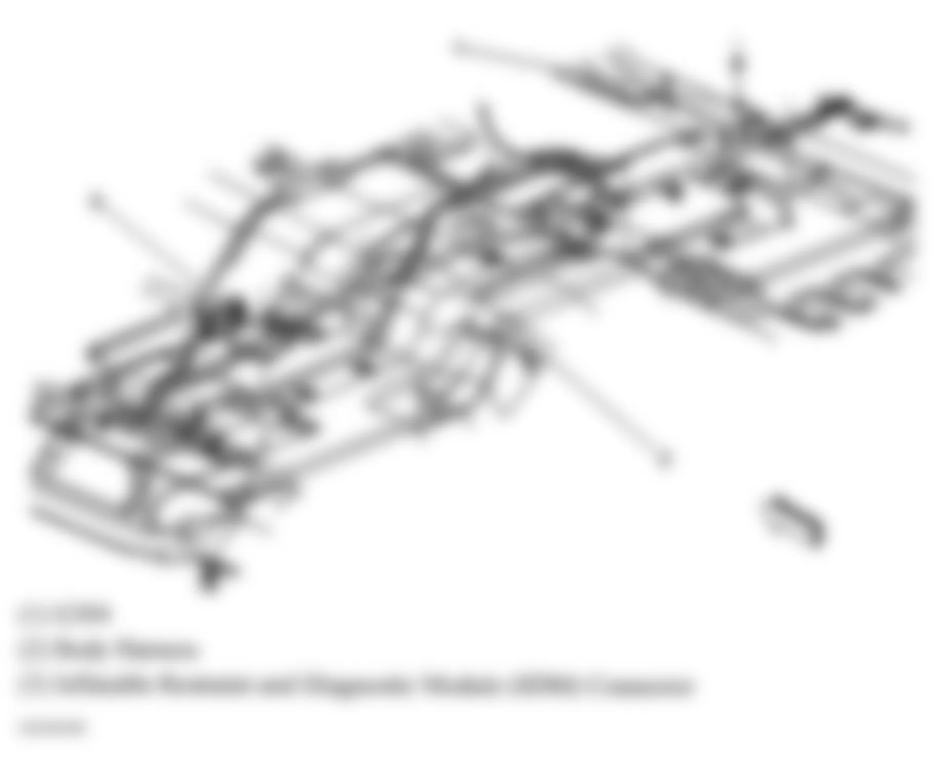
Fig. 19: Hummer H2 2005 - Component Locations - Right "B" Pillar
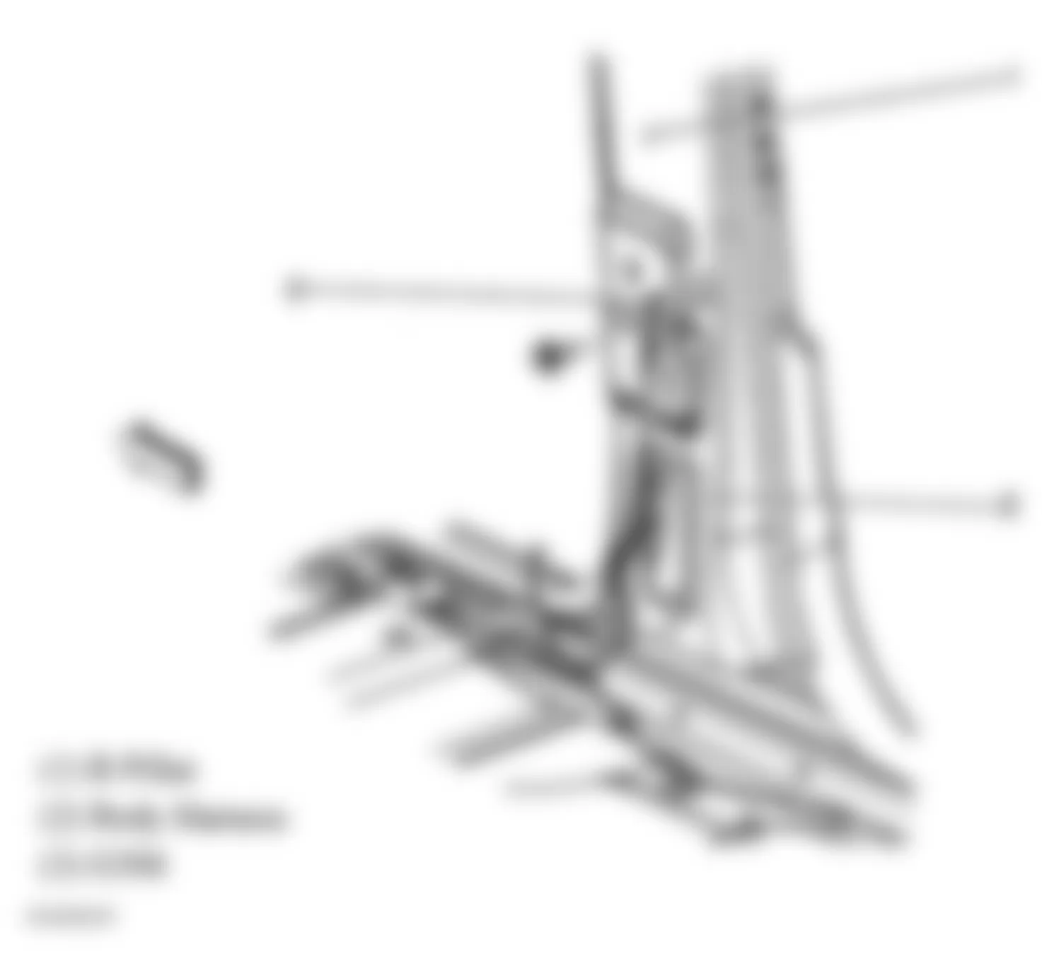
Fig. 20: Hummer H2 2005 - Component Locations - Right Frame Rail
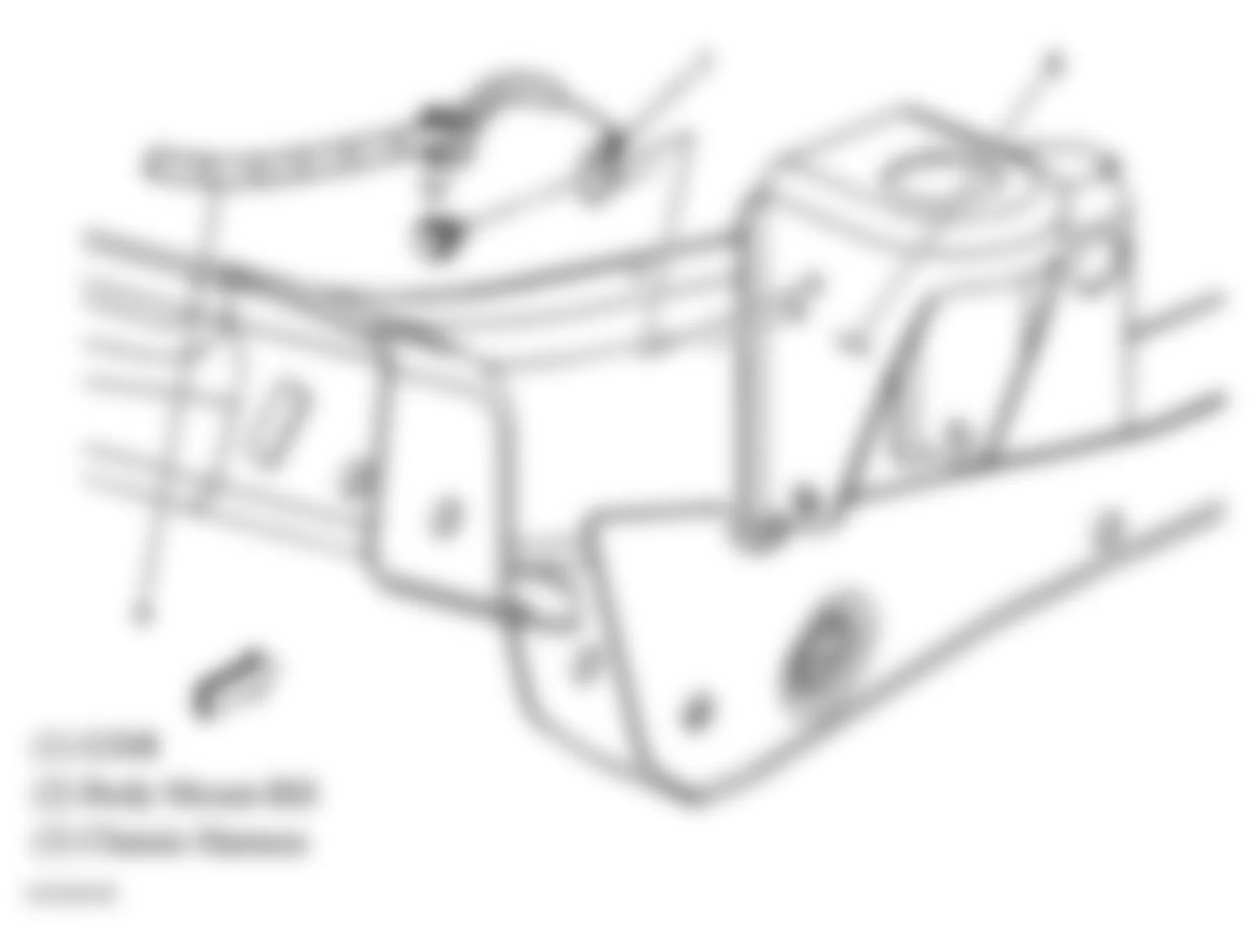
Fig. 21: Hummer H2 2005 - Component Locations - Left Frame Rail
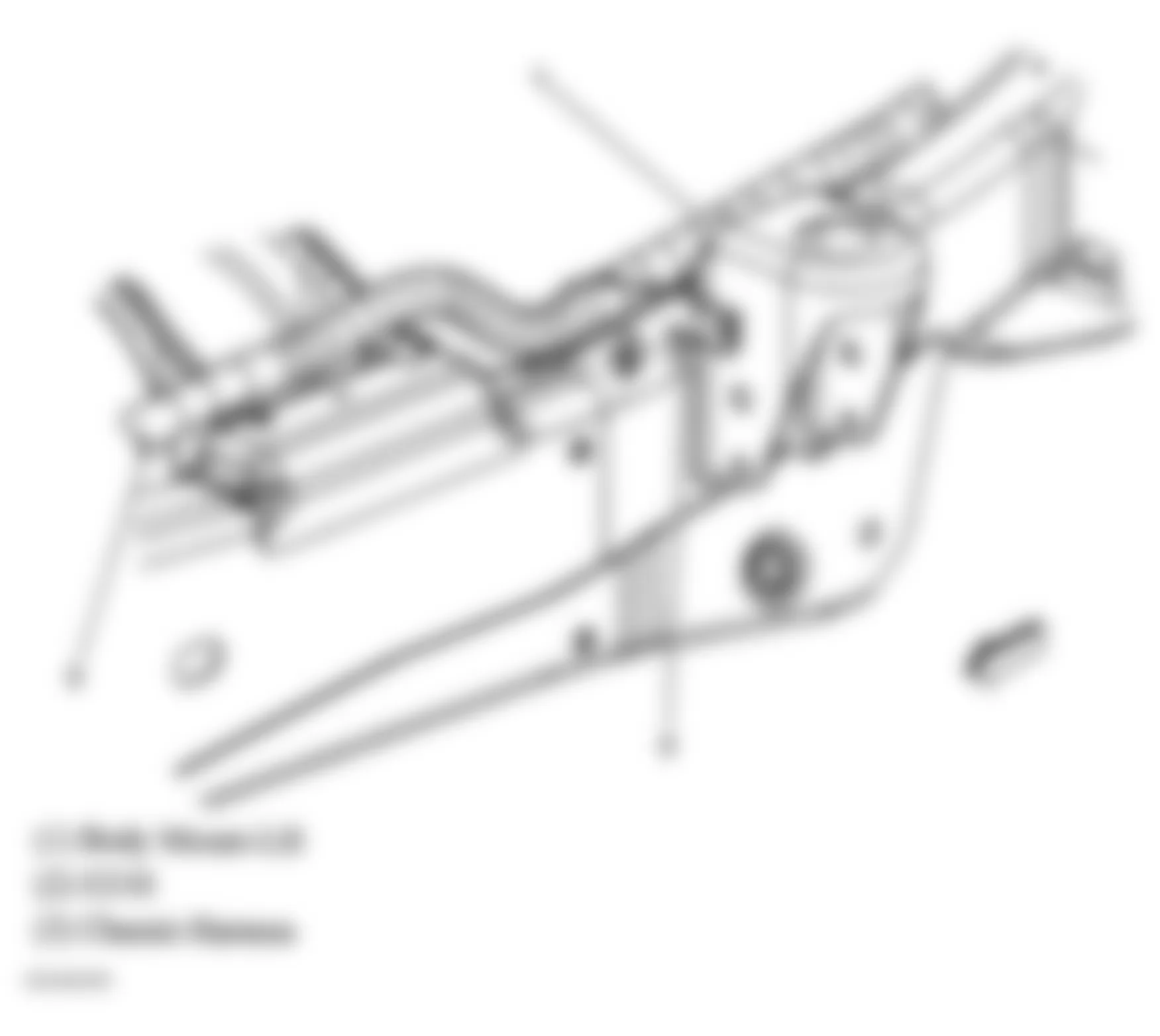
Fig. 22: Hummer H2 2005 - Component Locations - Rear Of Left Frame Rail
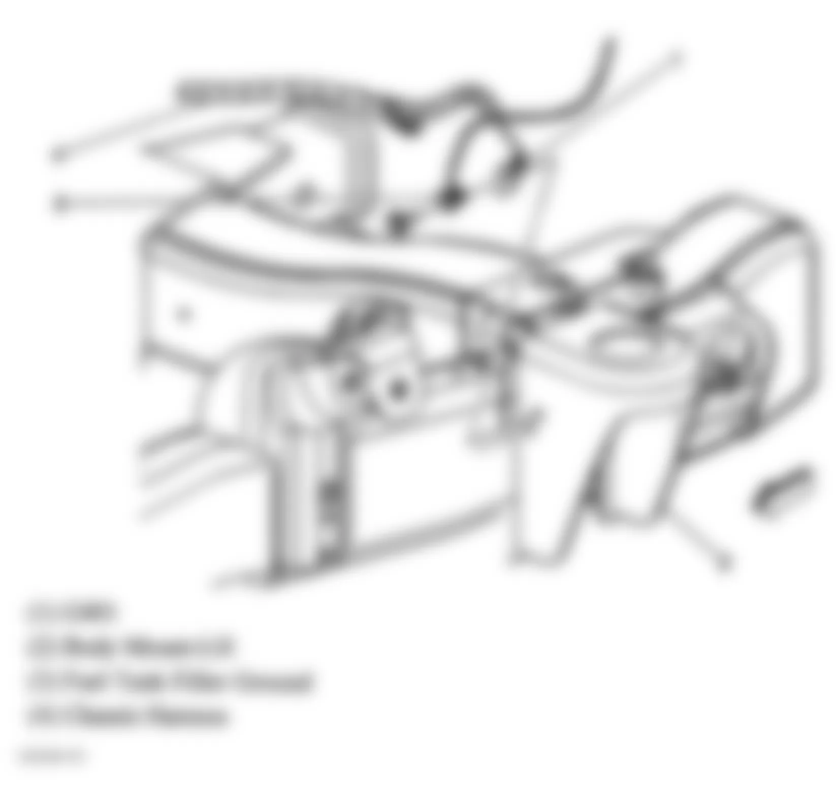
Fig. 23: Hummer H2 2005 - Component Locations - Rear Of Right Frame Rail
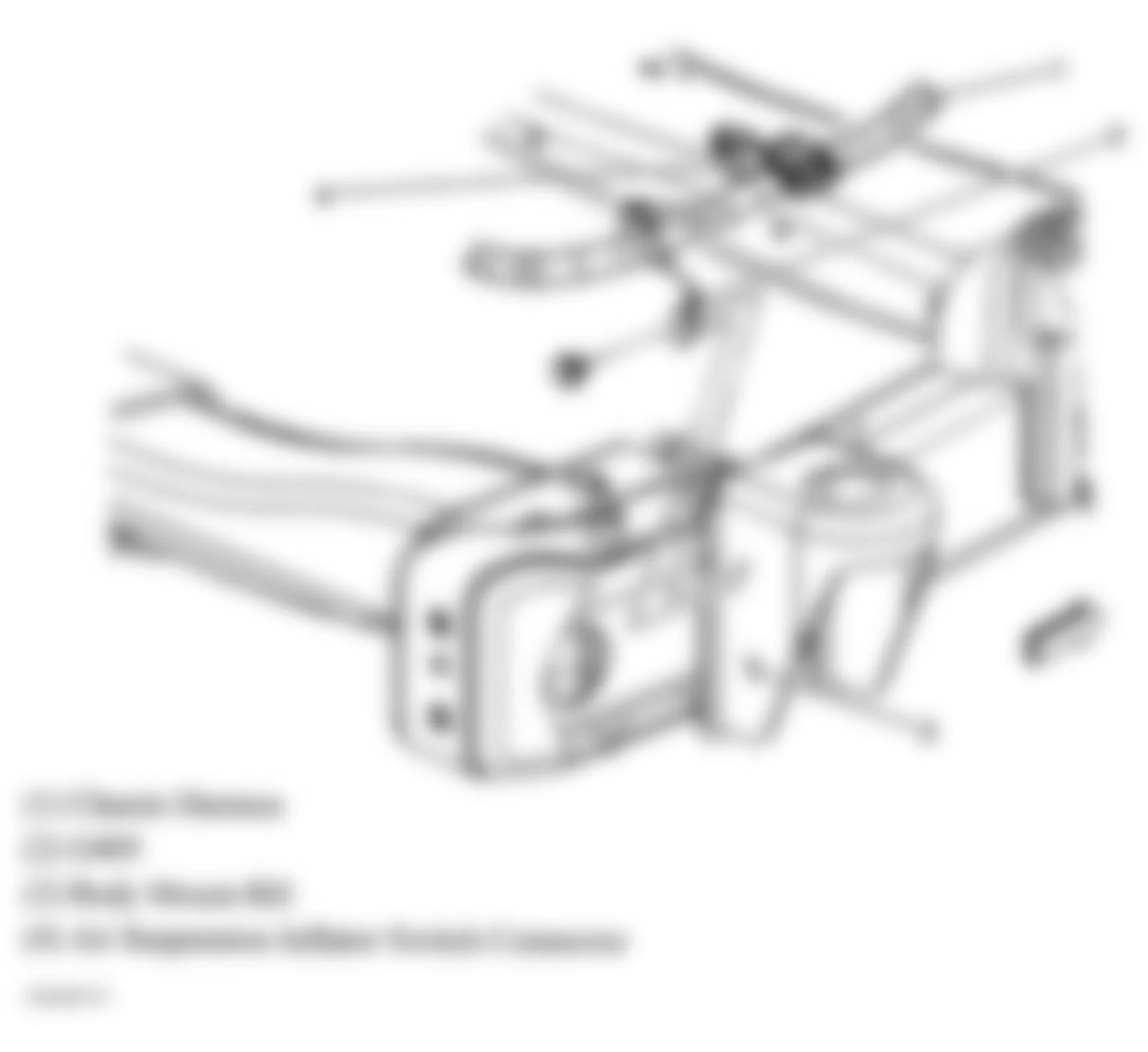
Fig. 24: Hummer H2 2005 - Component Locations - Right Rear Corner Of Vehicle
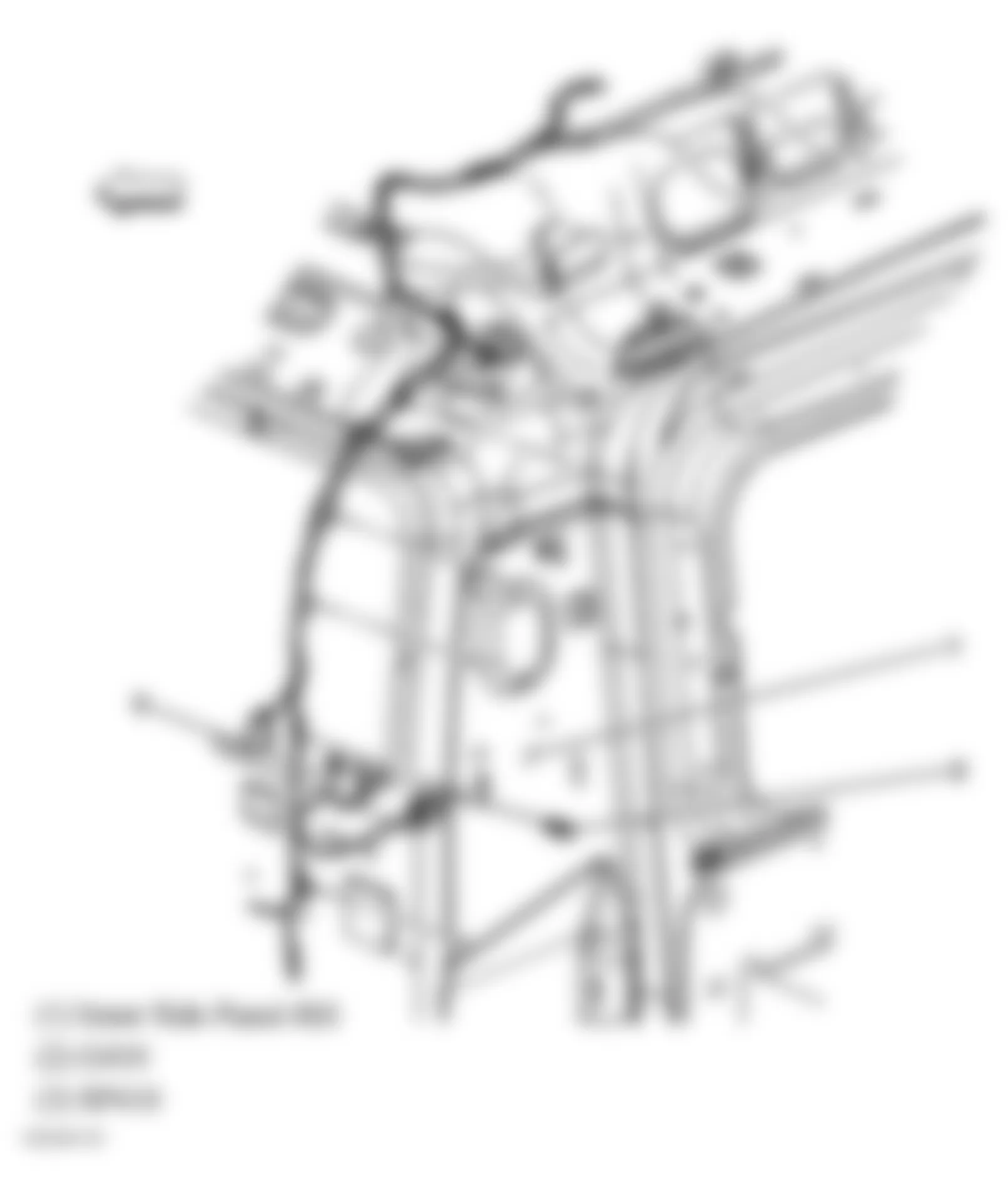
Fig. 25: Hummer H2 2005 - Component Locations - Rear Bumper Fascia
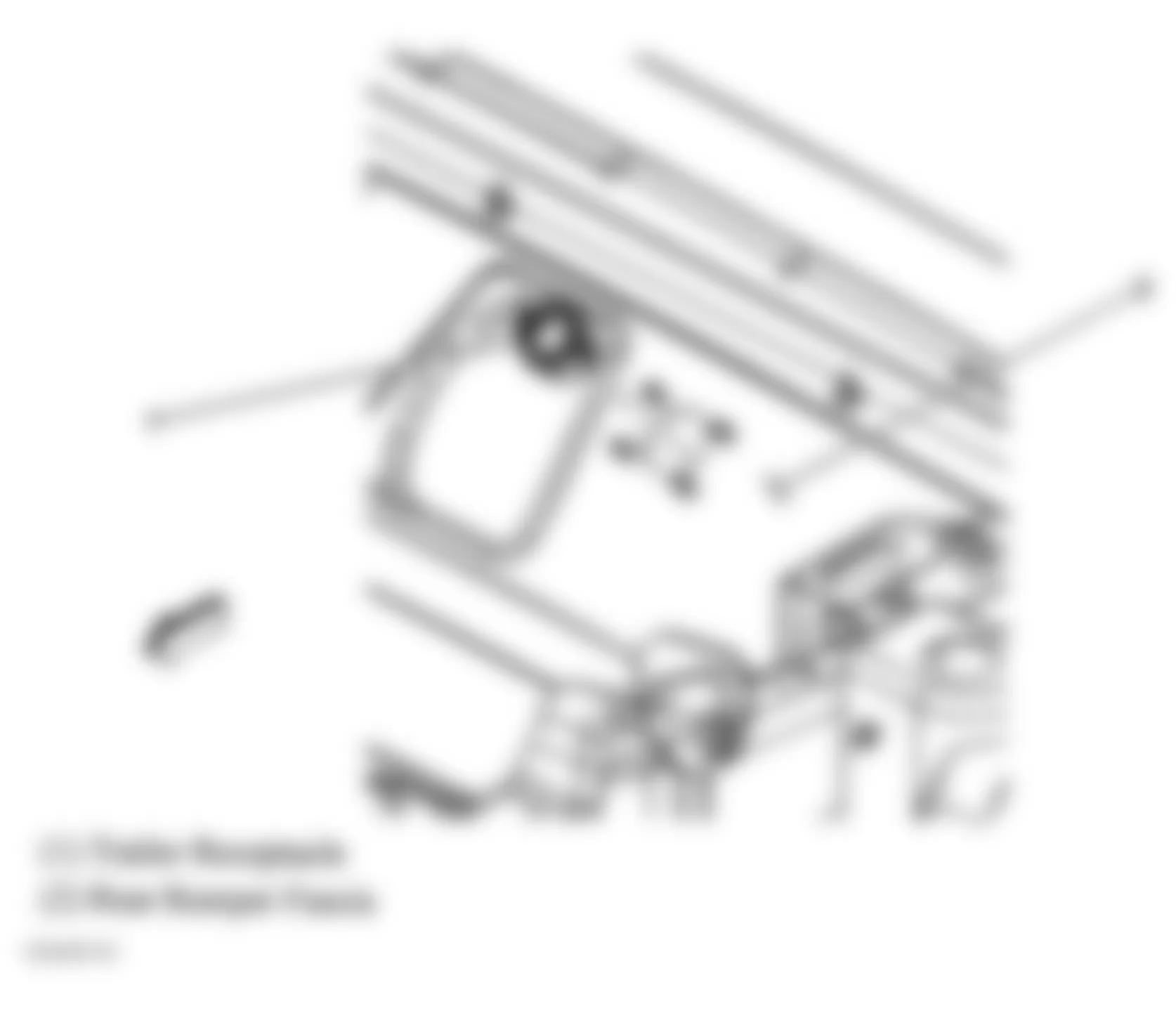
Fig. 26: Hummer H2 2005 - Component Locations - Instrument Panel Fuse Block
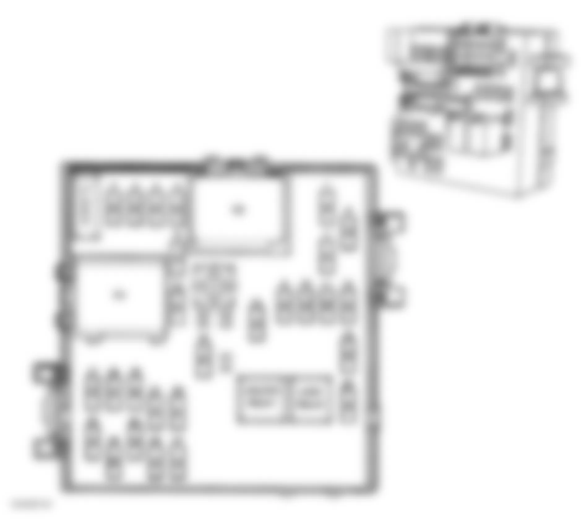
Fig. 27: Hummer H2 2005 - Component Locations - Instrument Panel Relay Block
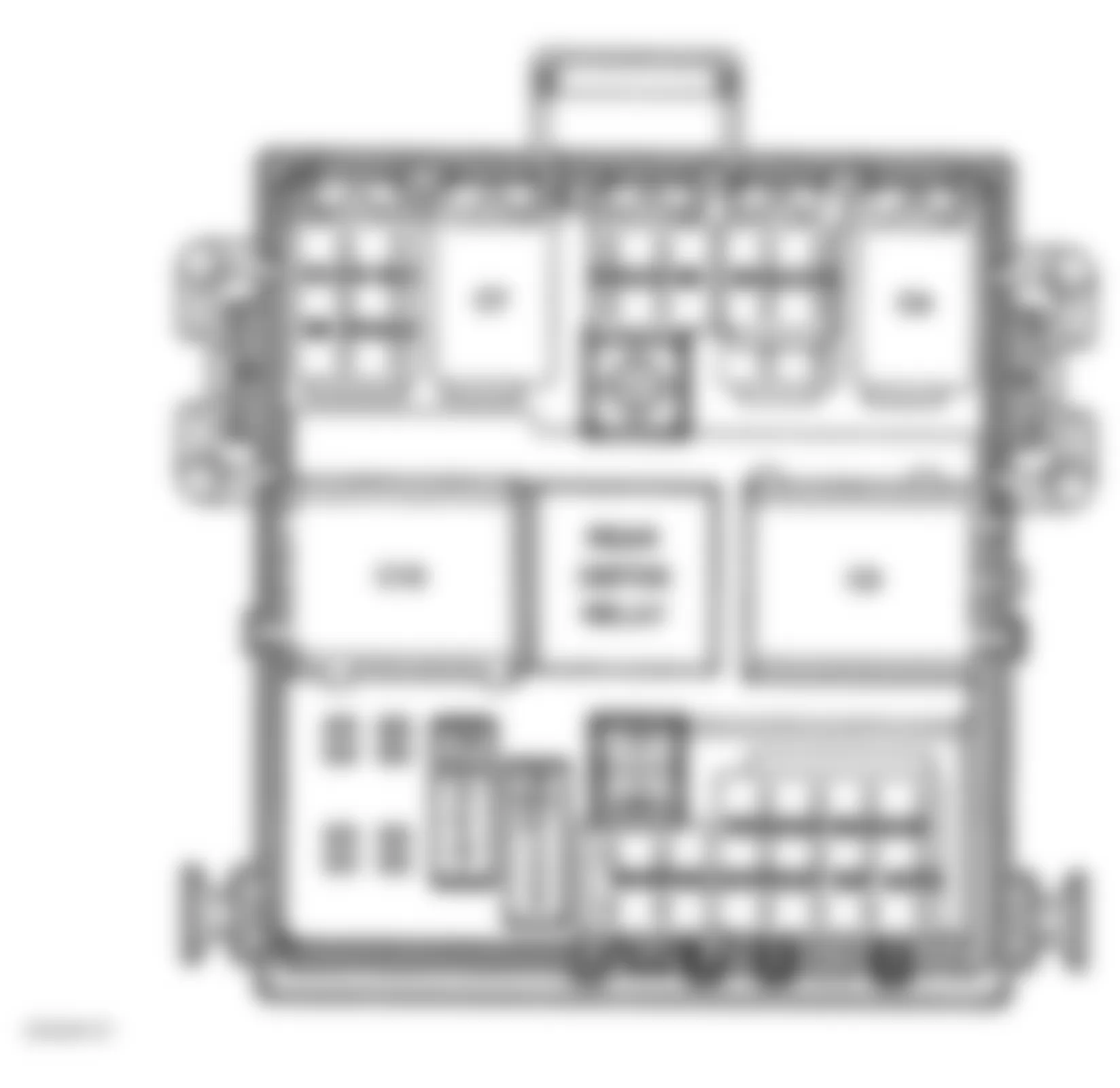
Fig. 28: Hummer H2 2005 - Component Locations - Right Rear Of Engine Compartment
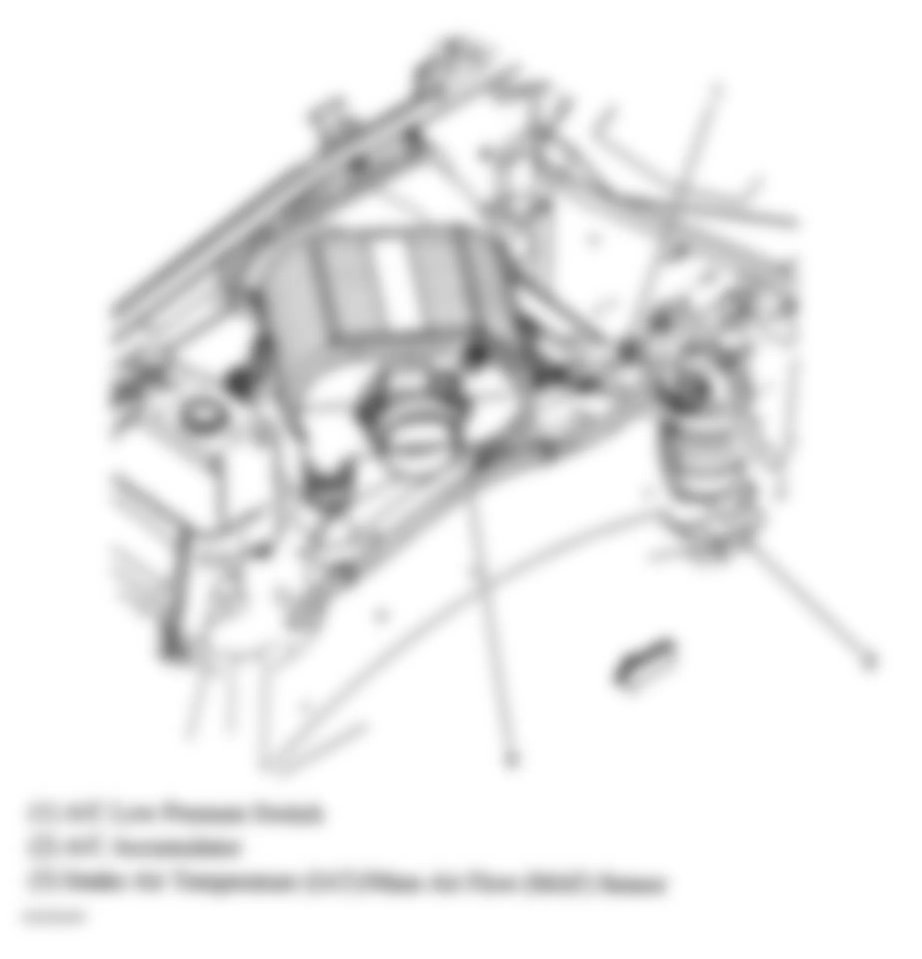
Fig. 29: Hummer H2 2005 - Component Locations - Lower Right Side Of Engine
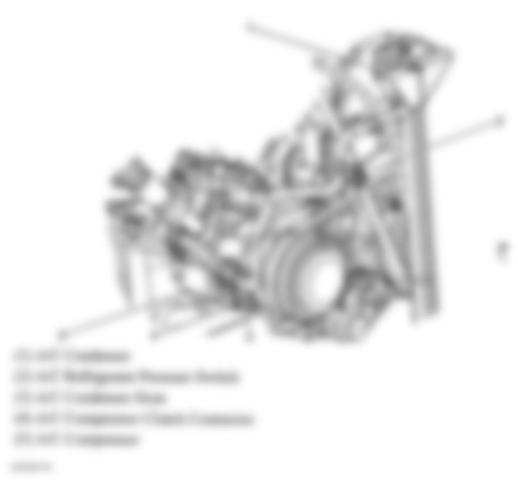
Fig. 30: Hummer H2 2005 - Component Locations - HVAC Subsystem Components
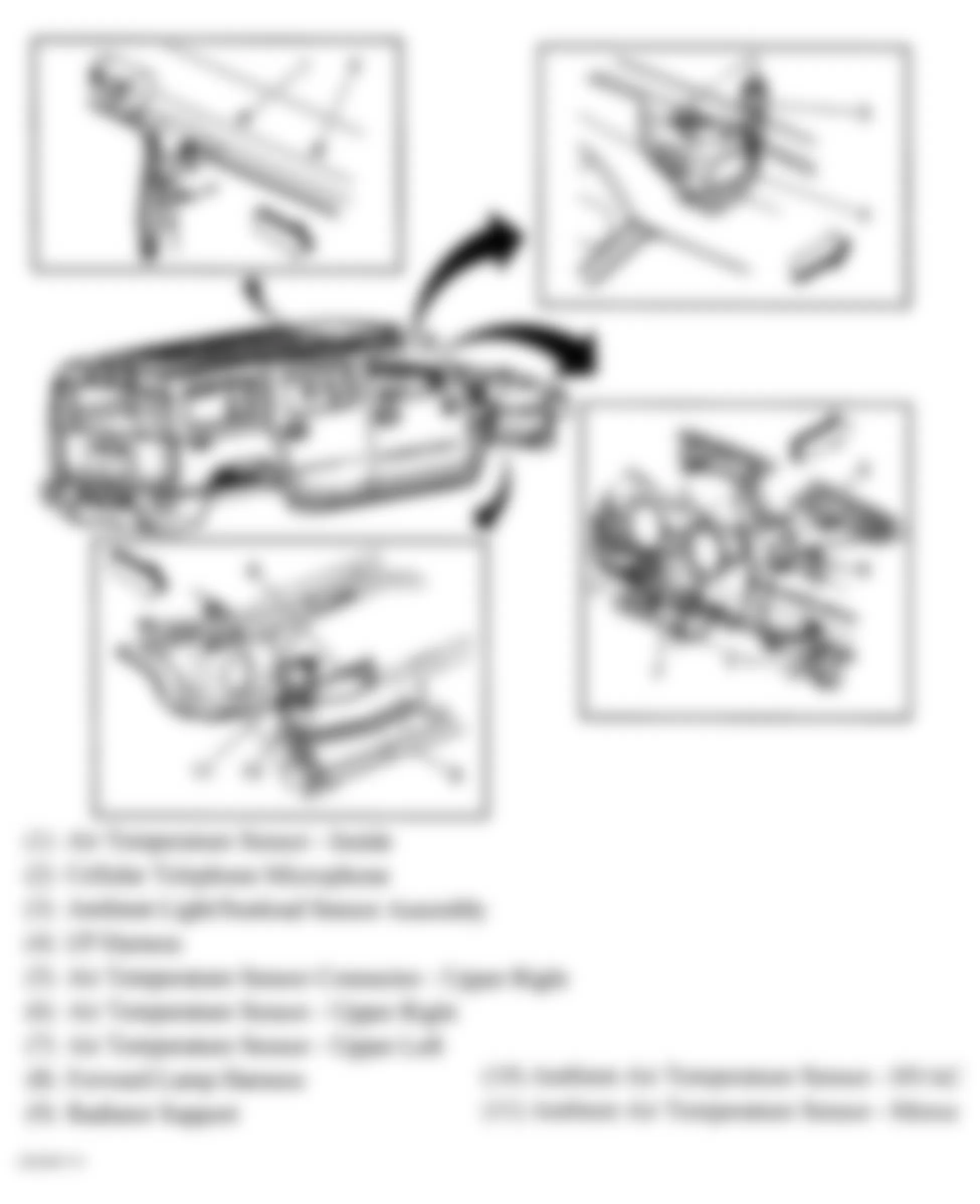
Fig. 31: Hummer H2 2005 - Component Locations - HVAC Module
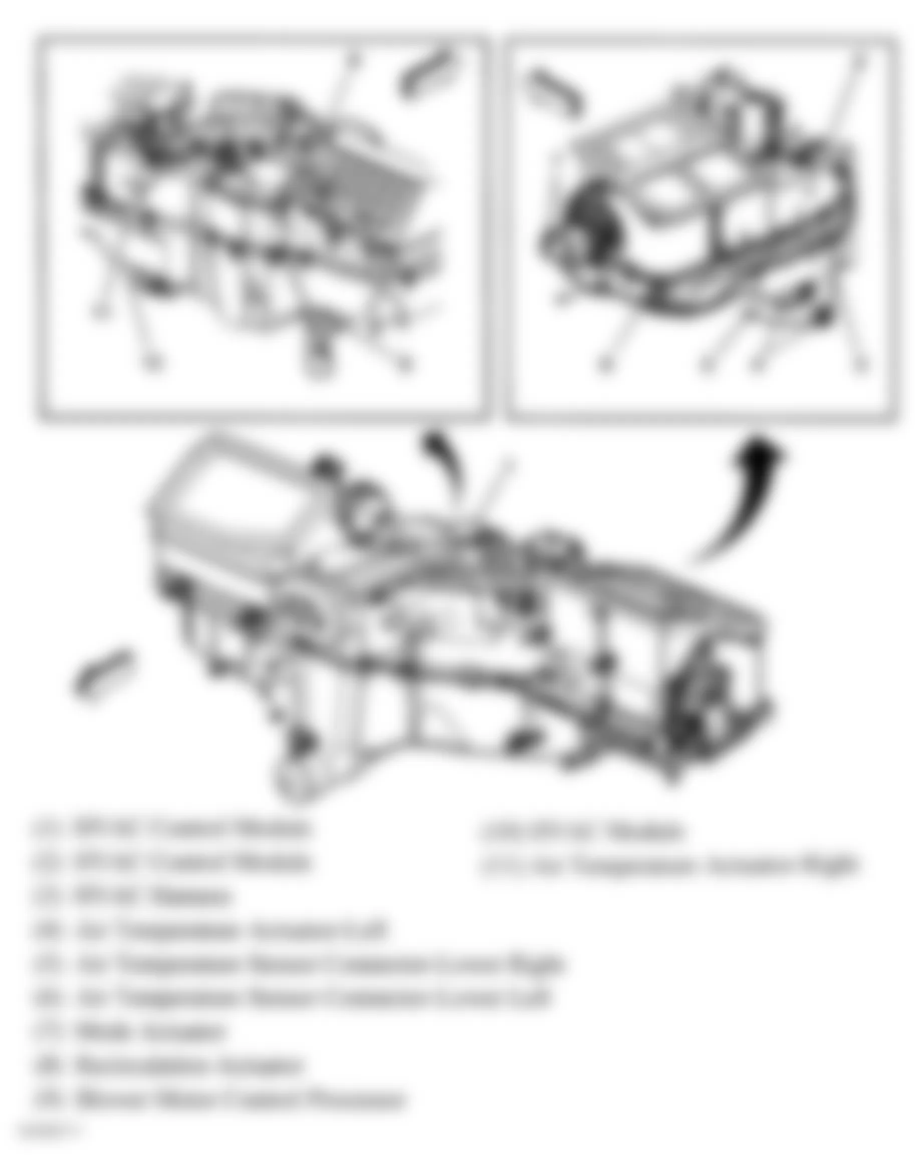
Fig. 32: Hummer H2 2005 - Component Locations - Steering Column (1 Of 2)
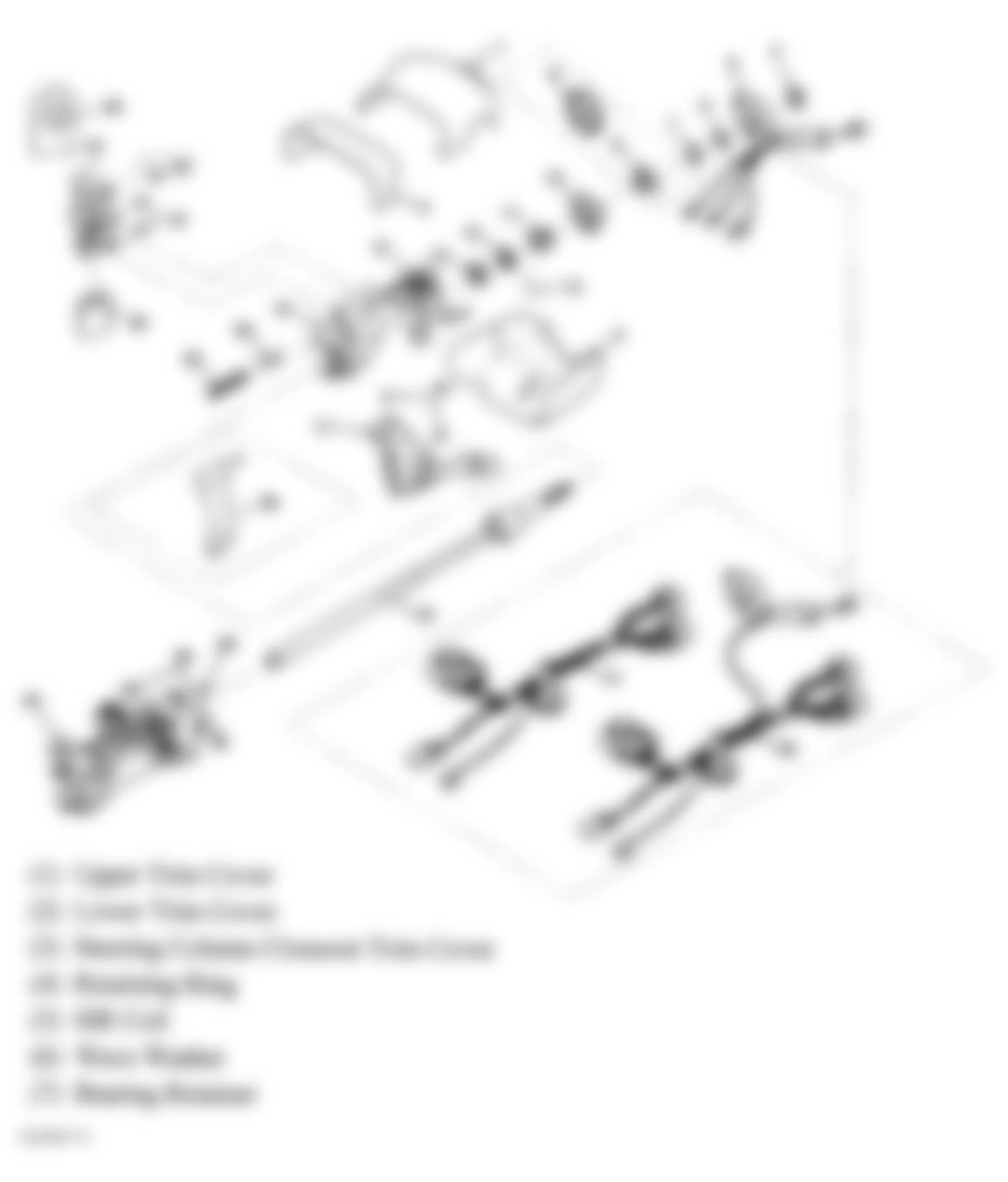
Fig. 33: Hummer H2 2005 - Component Locations - Steering Column (2 Of 2)
Fig. 34: Hummer H2 2005 - Component Locations - Air Suspension Components
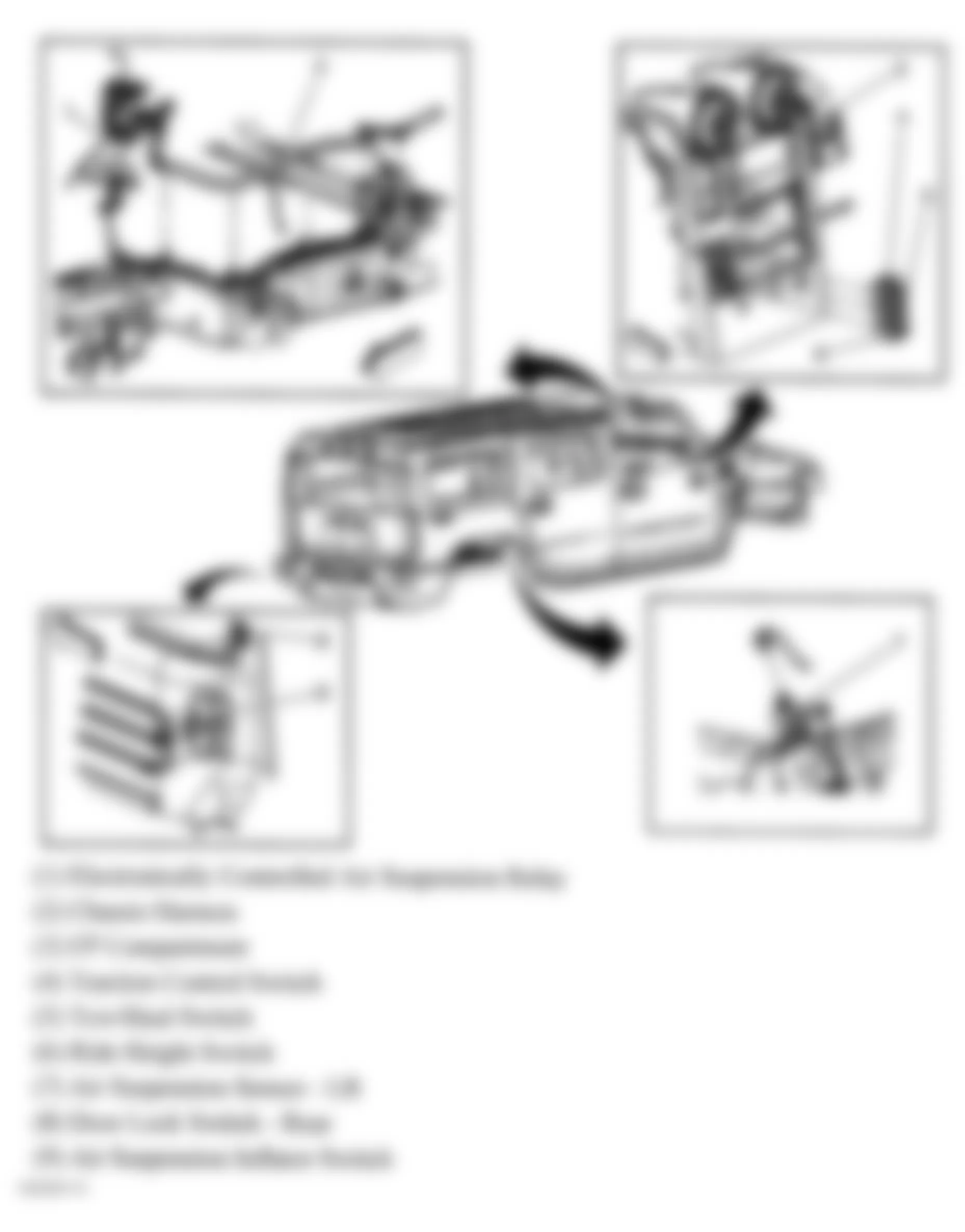
Fig. 35: Hummer H2 2005 - Component Locations - Locking Differential
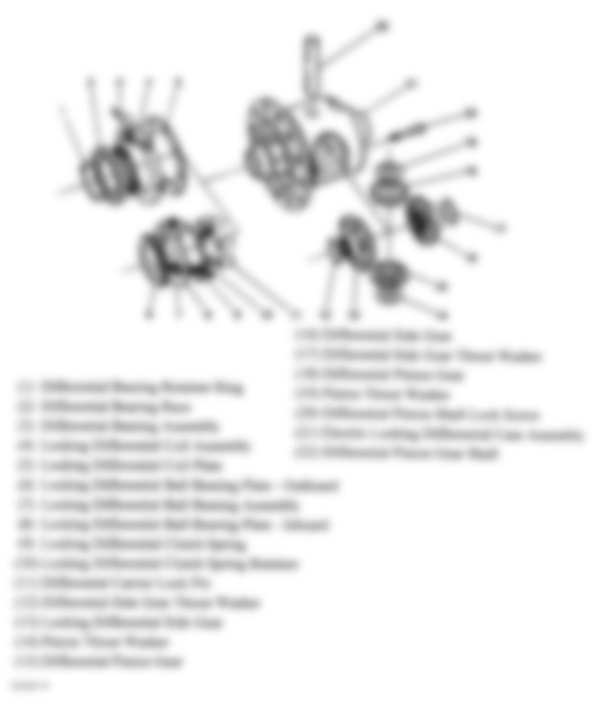
Fig. 36: Hummer H2 2005 - Component Locations - Rear Axle
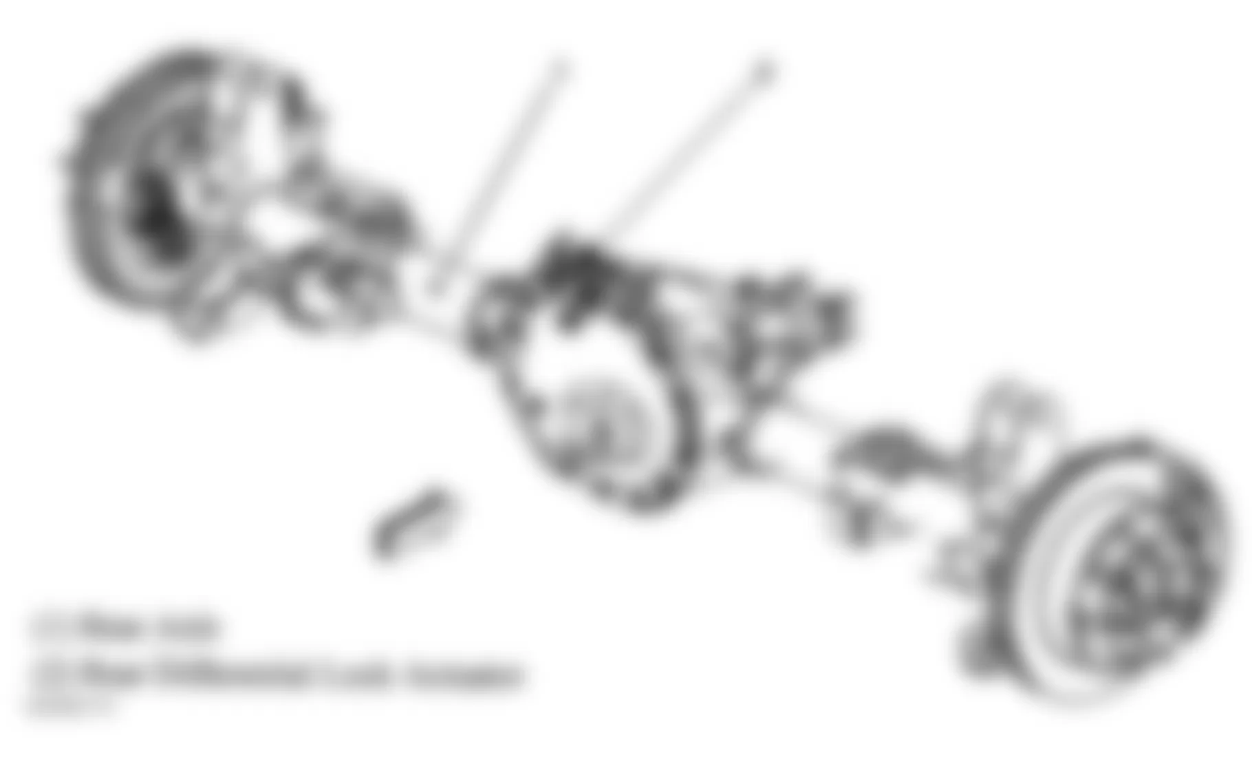
Fig. 37: Hummer H2 2005 - Component Locations - Transfer Case
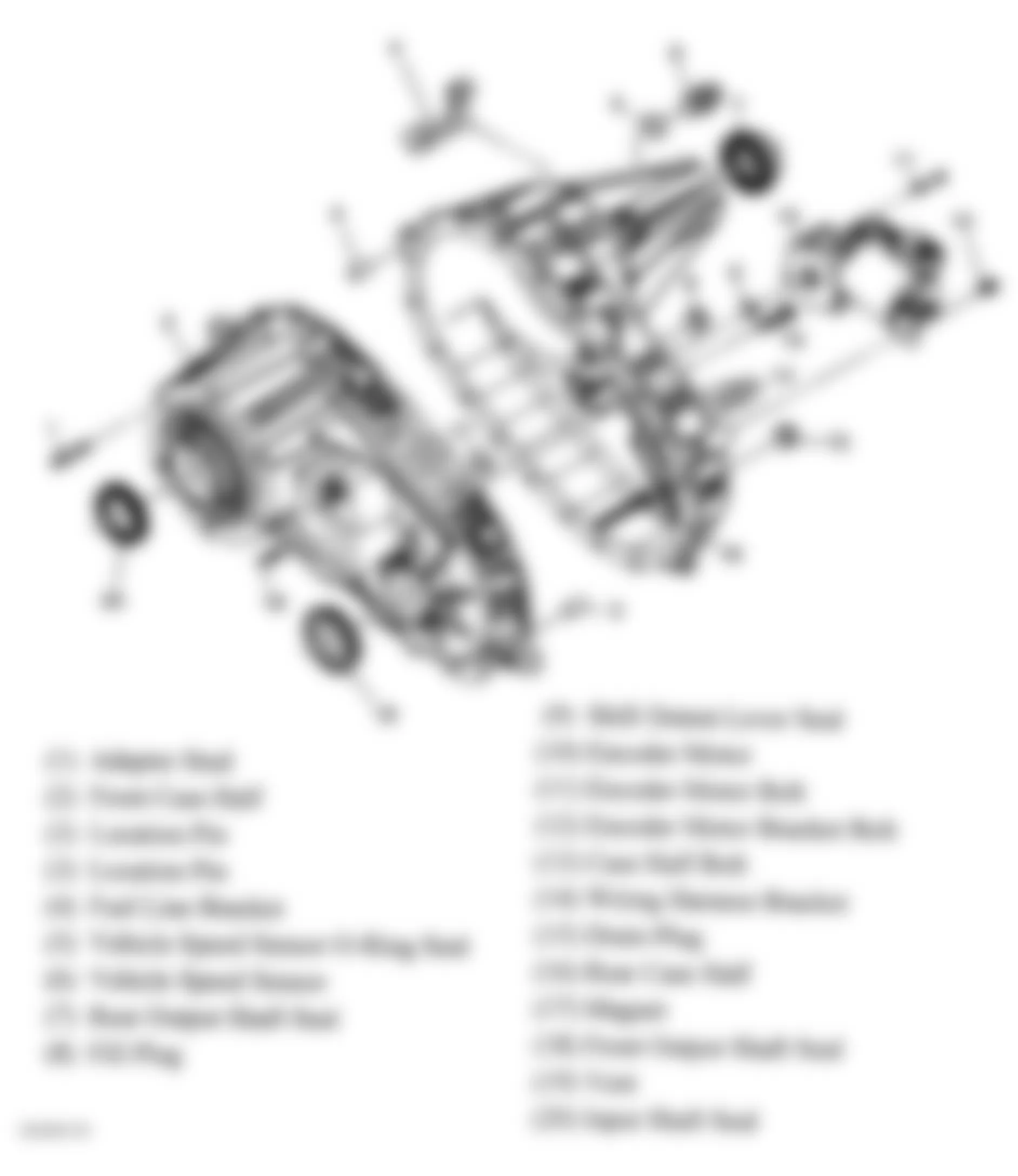
Fig. 38: Hummer H2 2005 - Component Locations - Rear Of Transmission
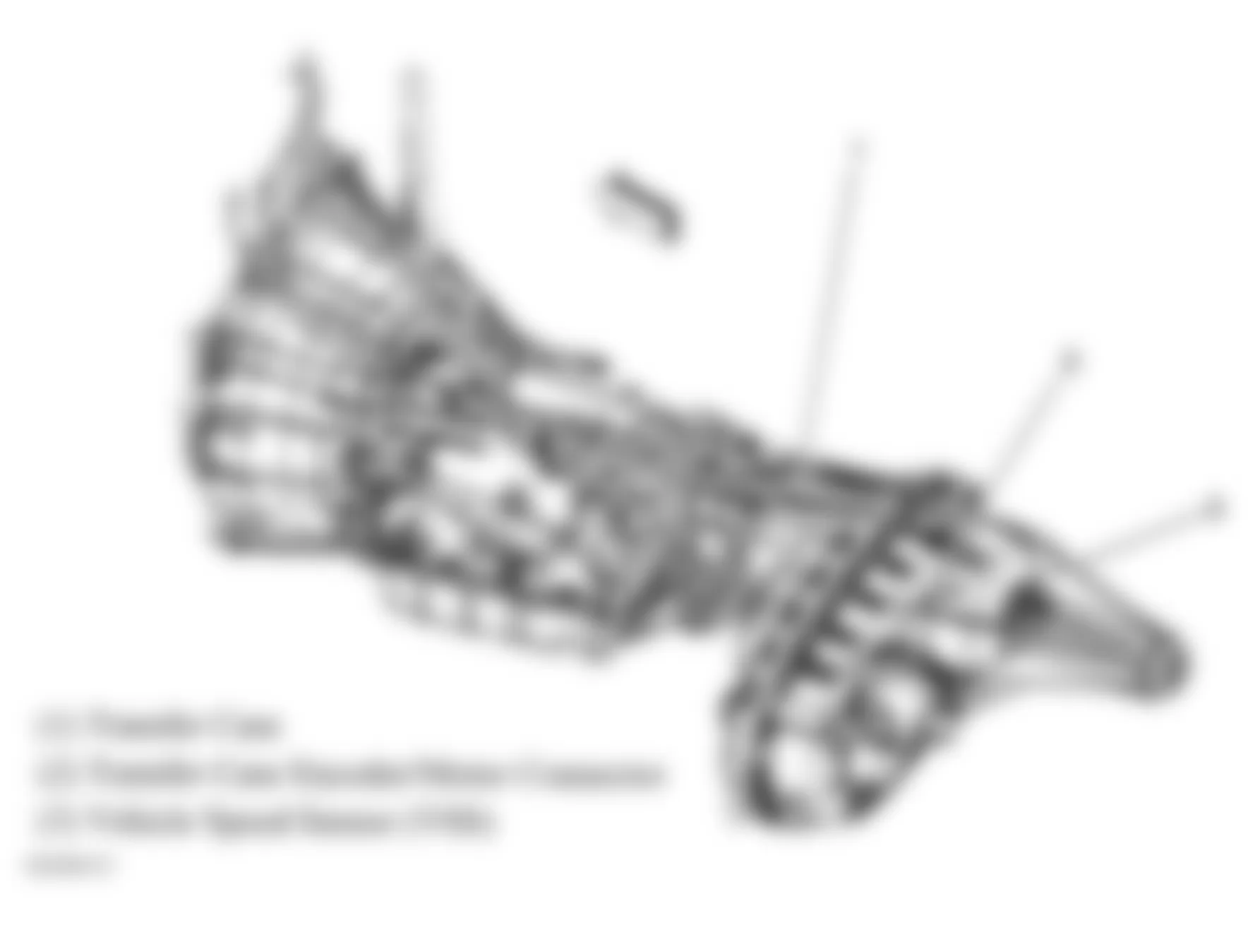
Fig. 39: Hummer H2 2005 - Component Locations - Left Rear Of Engine Compartment
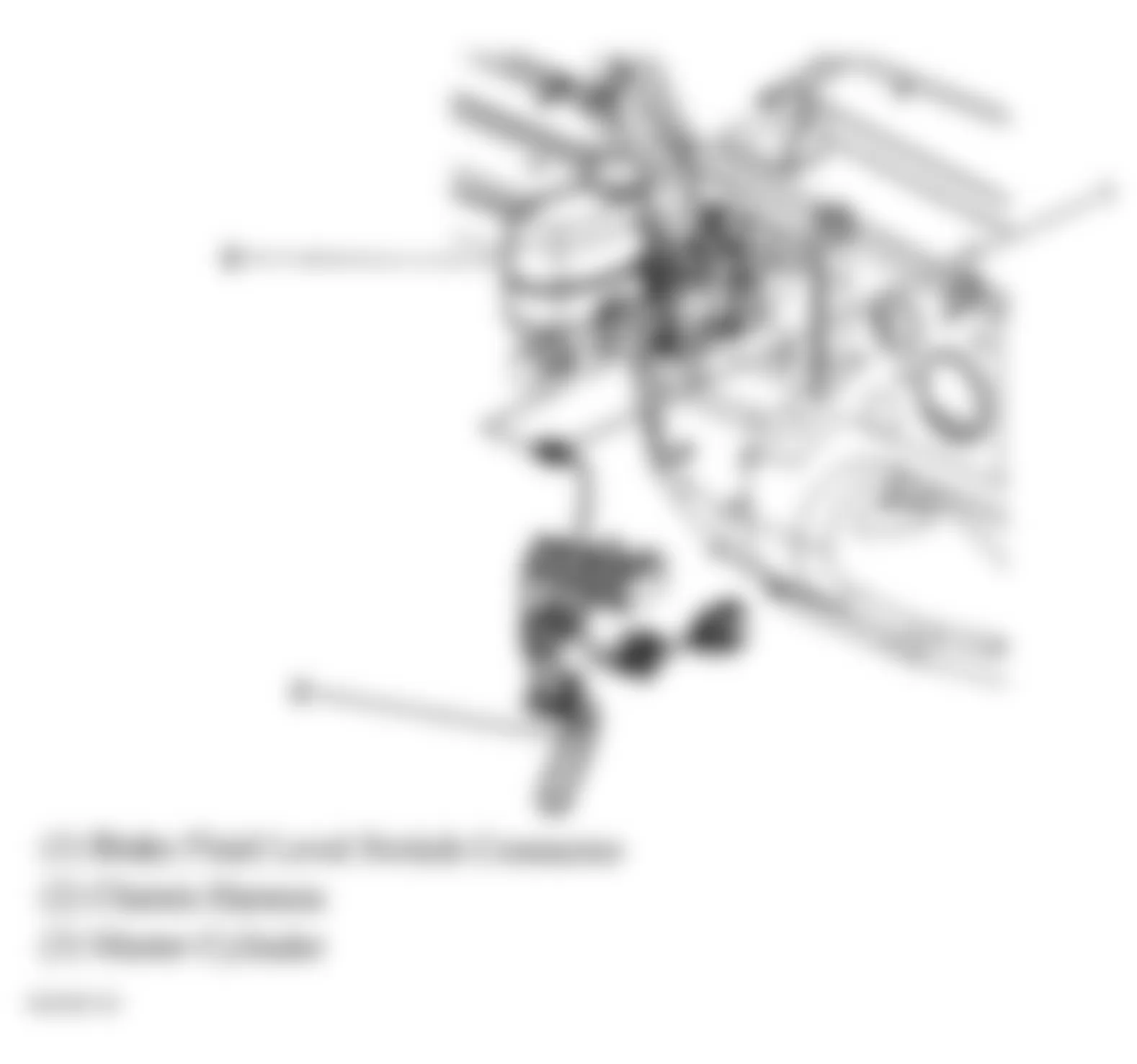
Fig. 40: Hummer H2 2005 - Component Locations - Lower Left Side Of Dash
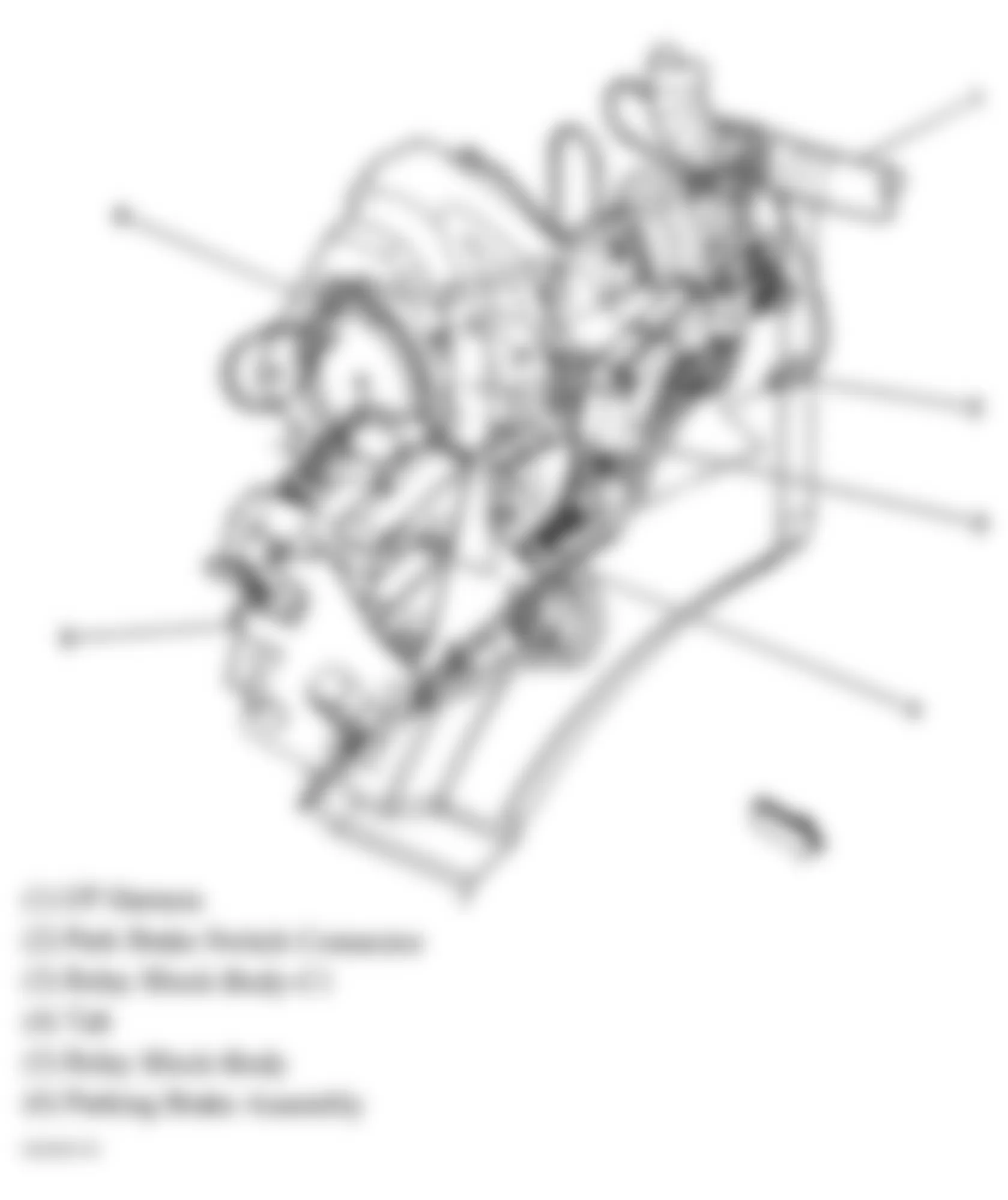
Fig. 41: Hummer H2 2005 - Component Locations - ABS Components
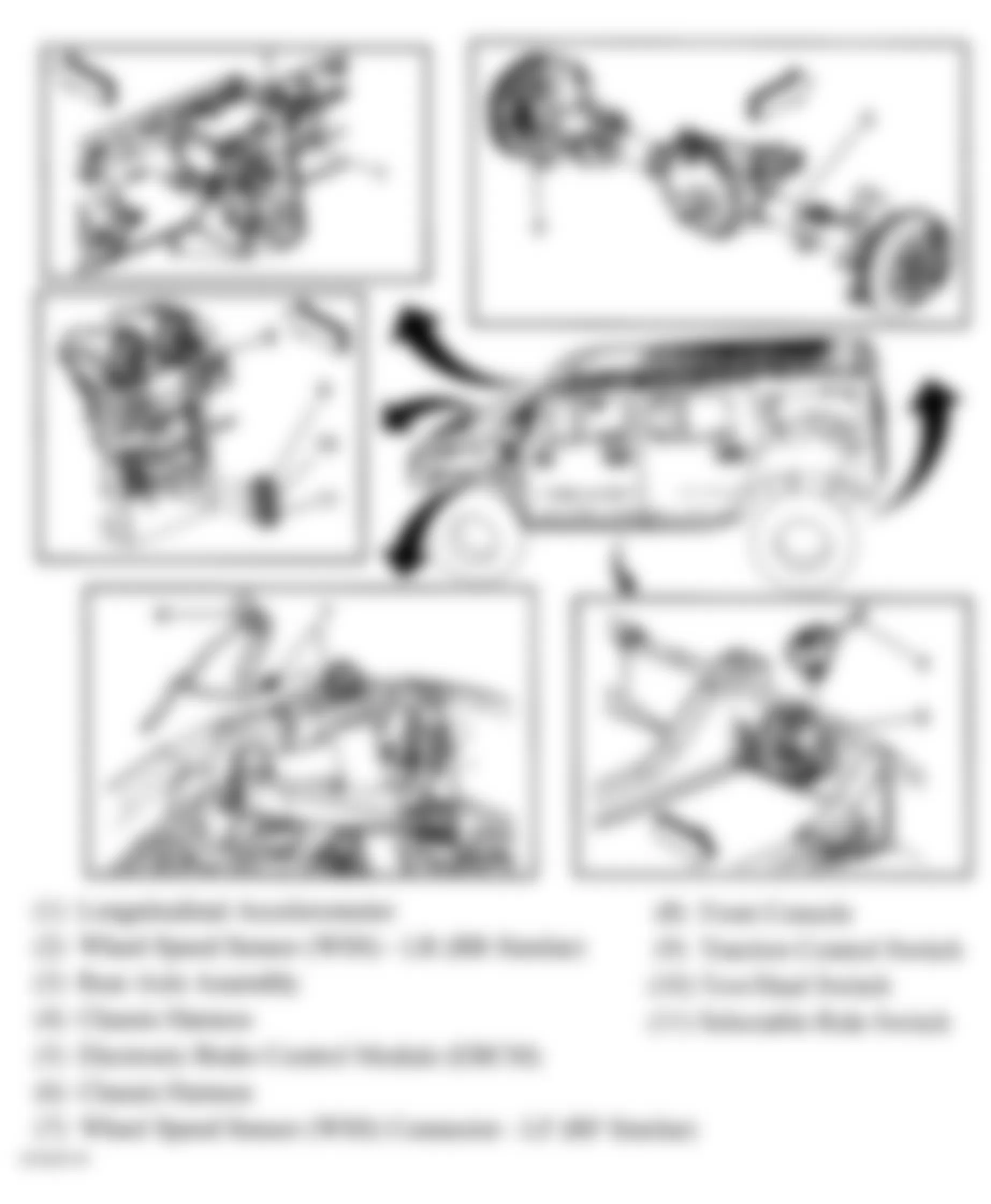
Fig. 42: Hummer H2 2005 - Component Locations - Left Side & Right Rear Of Engine
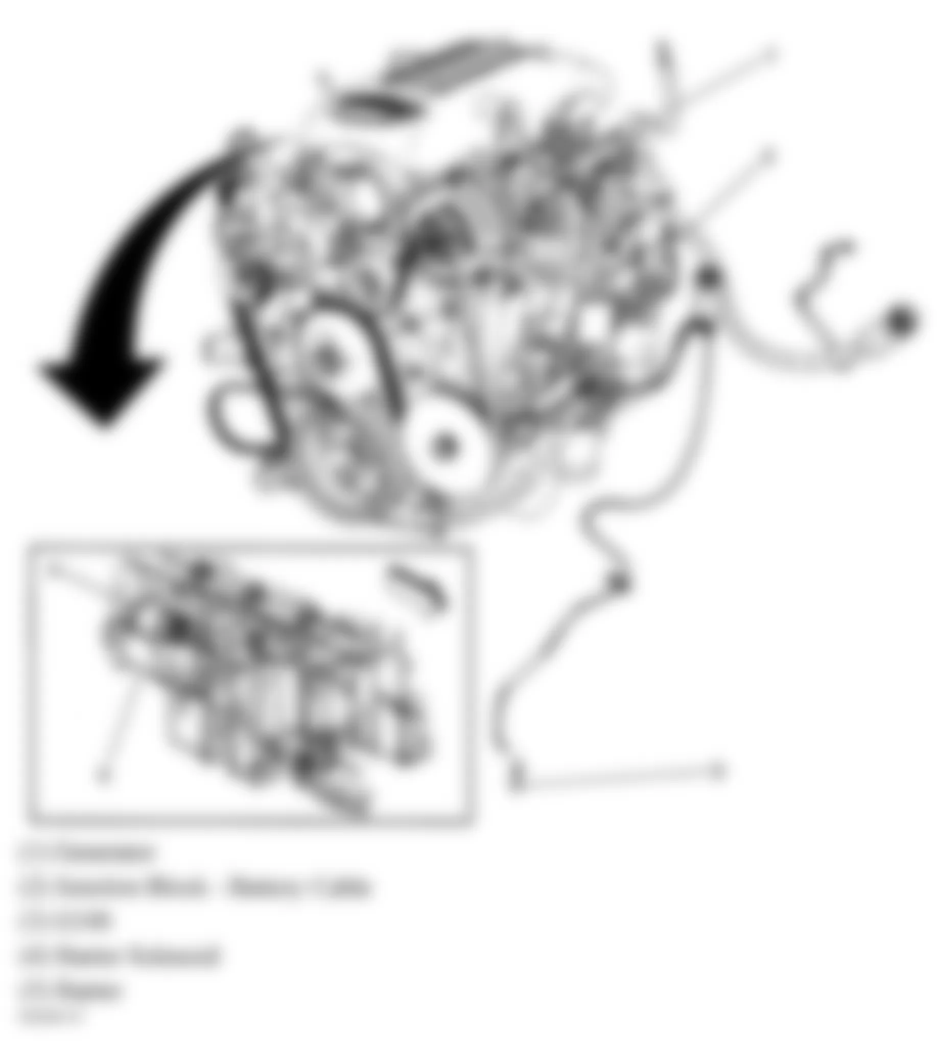
Fig. 43: Hummer H2 2005 - Component Locations - Steering Column
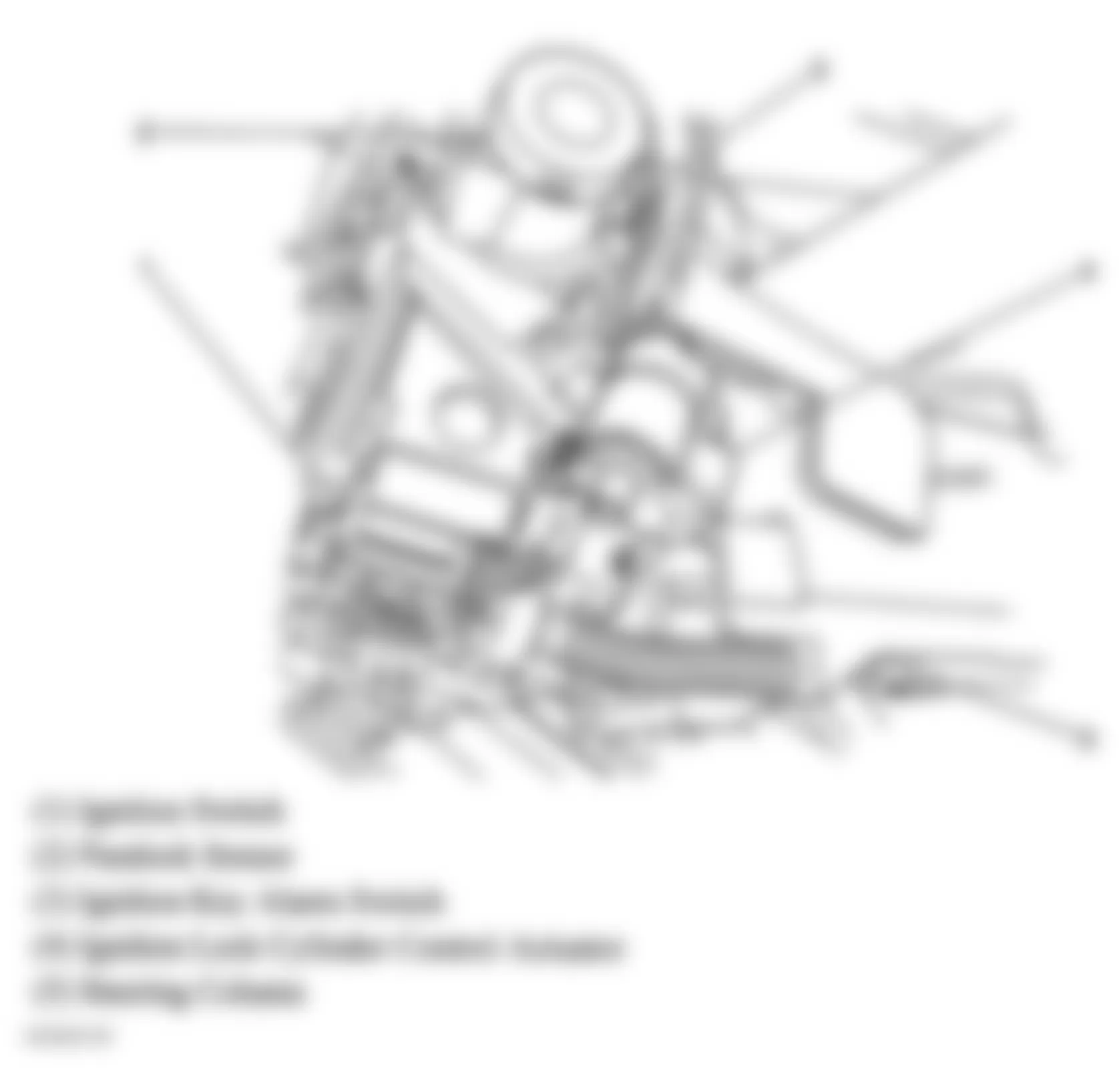
Fig. 44: Hummer H2 2005 - Component Locations - Lower Left Side Of Dash
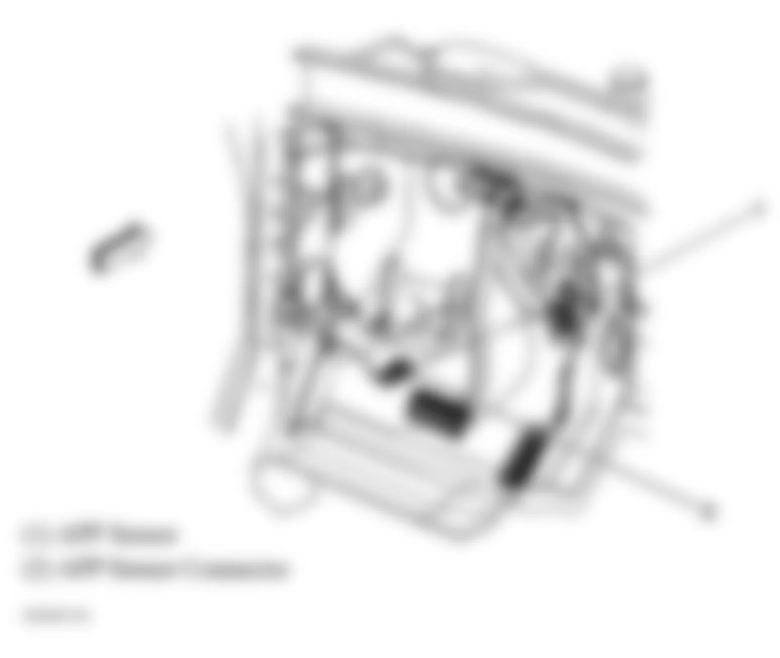
Fig. 45: Hummer H2 2005 - Component Locations - Left Side Of Engine
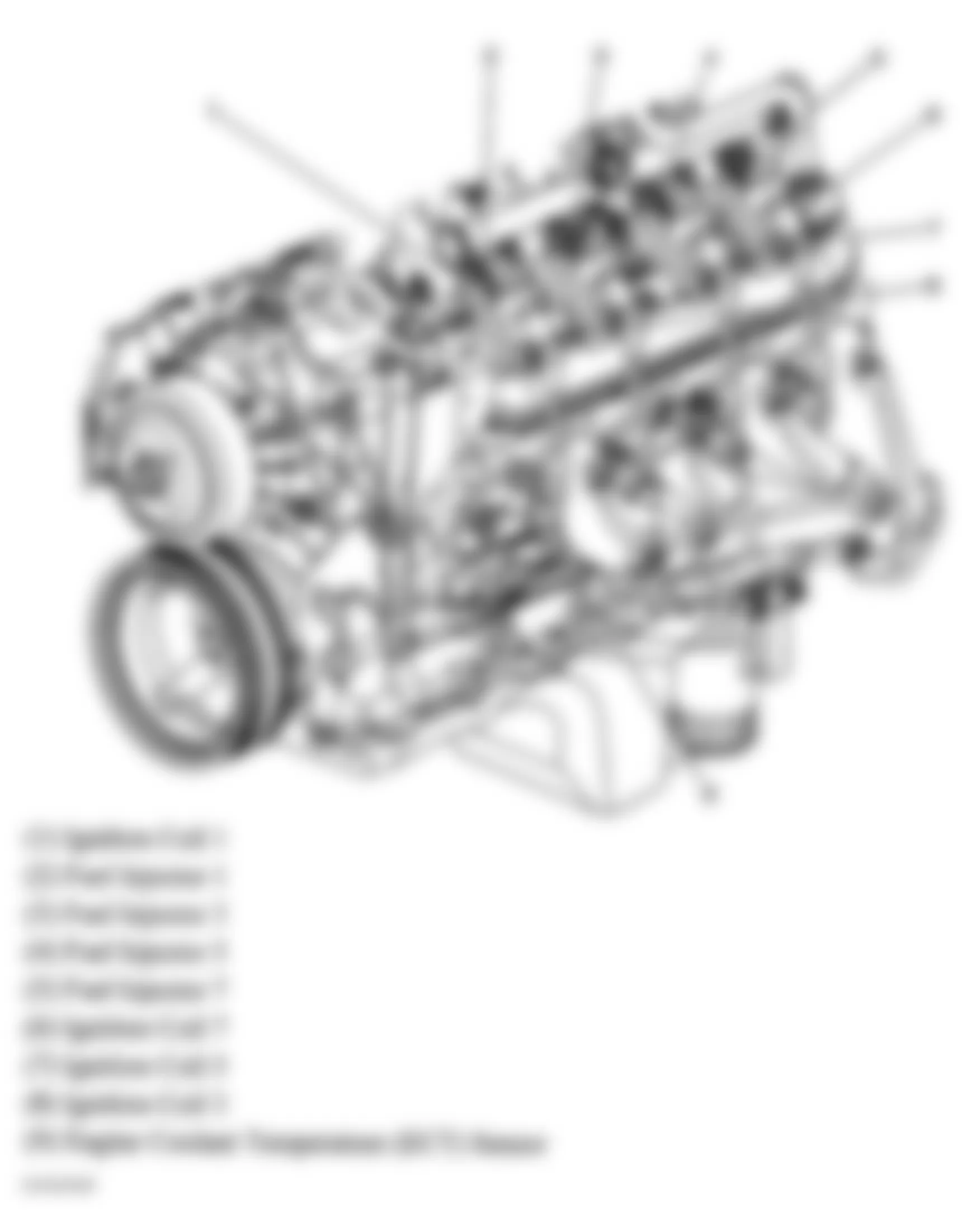
Fig. 46: Hummer H2 2005 - Component Locations - Lower Right Side Of Engine
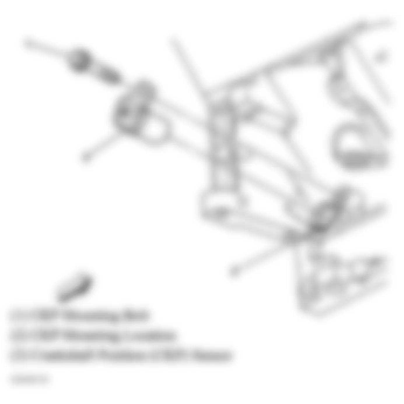
Fig. 47: Hummer H2 2005 - Component Locations - Engine Compartment & Lower Right Side Of Engine
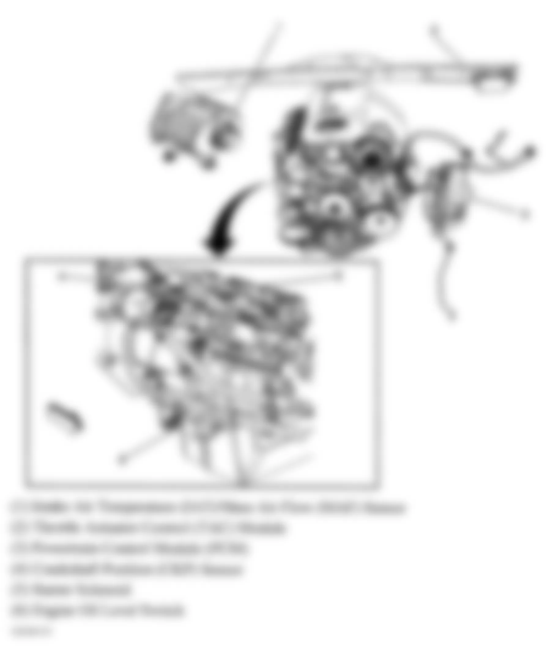
Fig. 48: Hummer H2 2005 - Component Locations - Right Rear, Left Rear & Front Of Engine
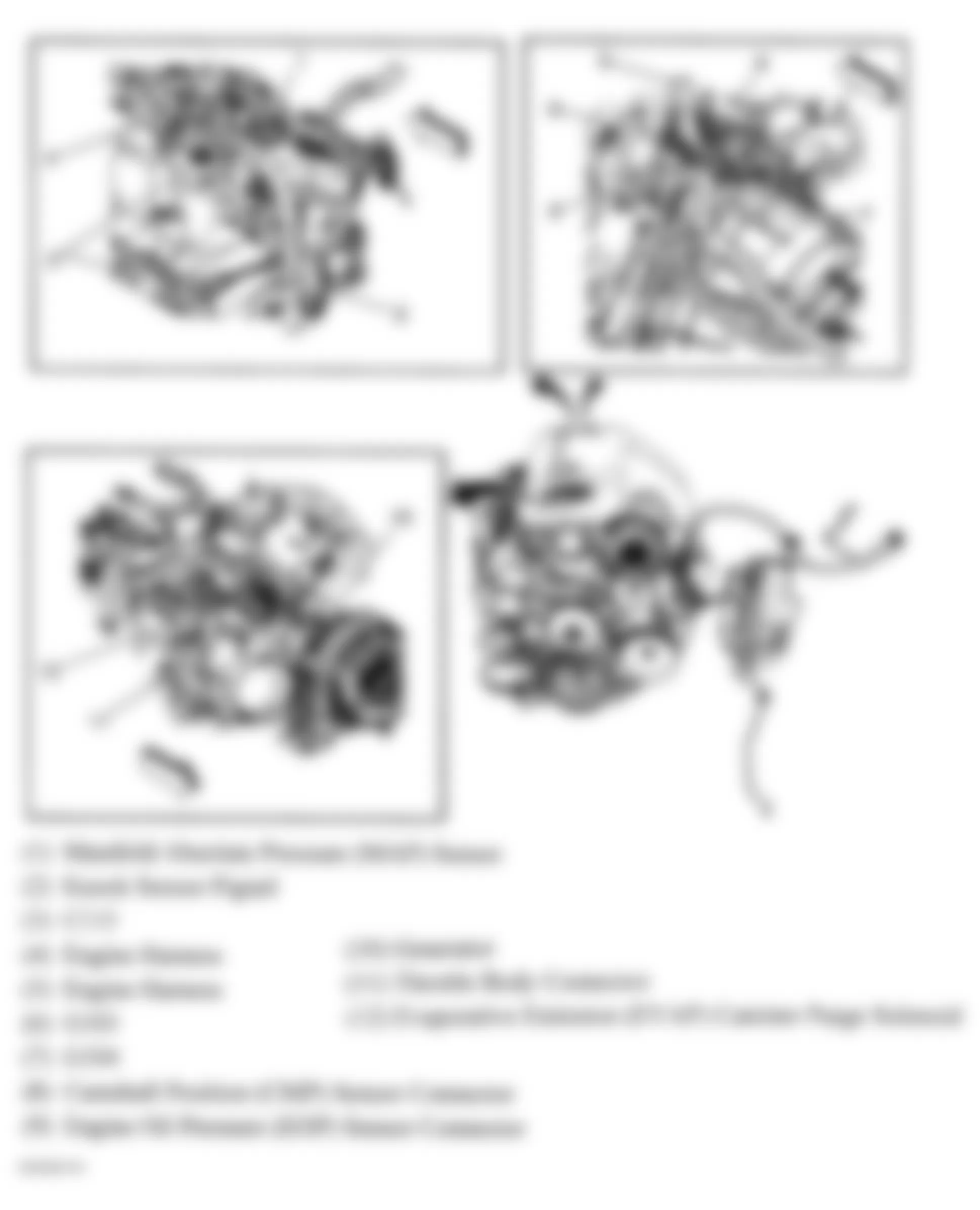
Fig. 49: Hummer H2 2005 - Component Locations - Frame
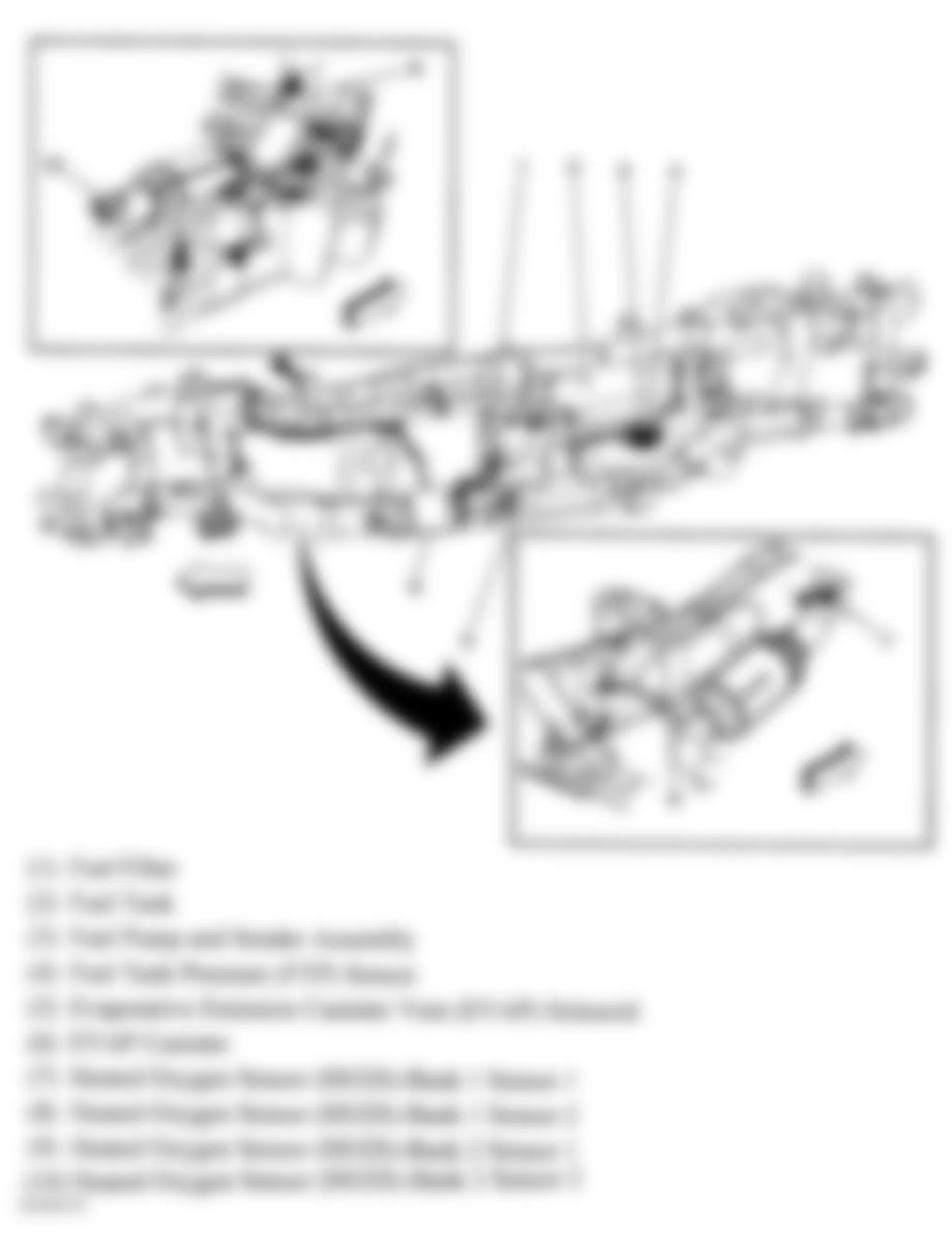
Fig. 50: Hummer H2 2005 - Component Locations - Top Of Engine
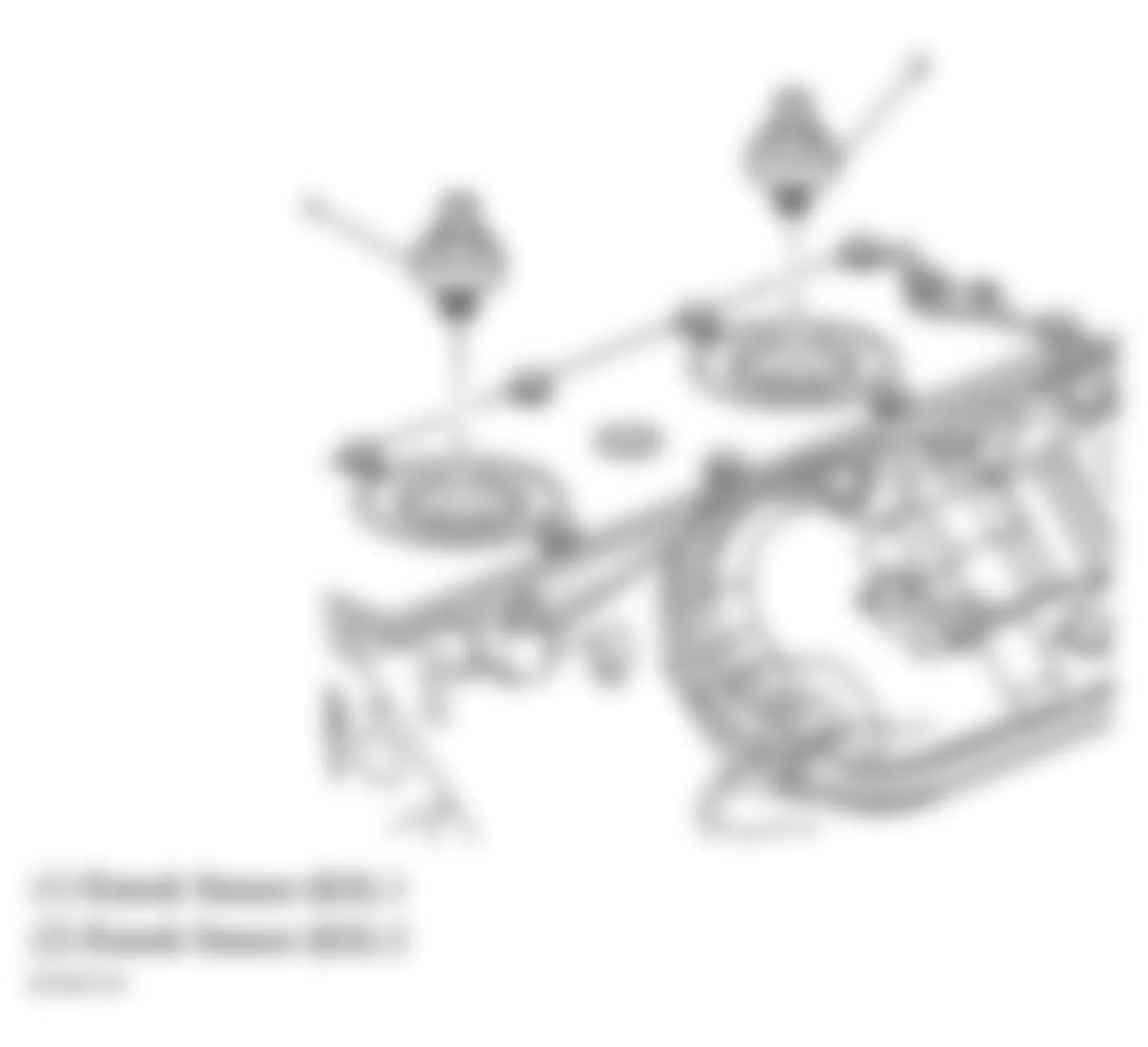
Fig. 51: Hummer H2 2005 - Component Locations - Left Side Of Dash
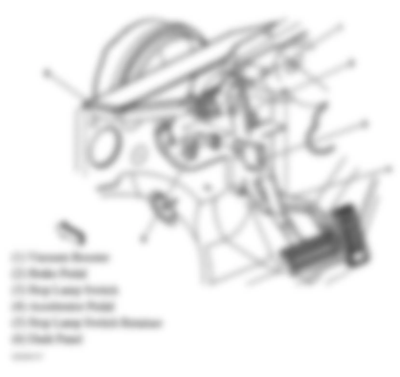
Fig. 52: Hummer H2 2005 - Component Locations - Transmission
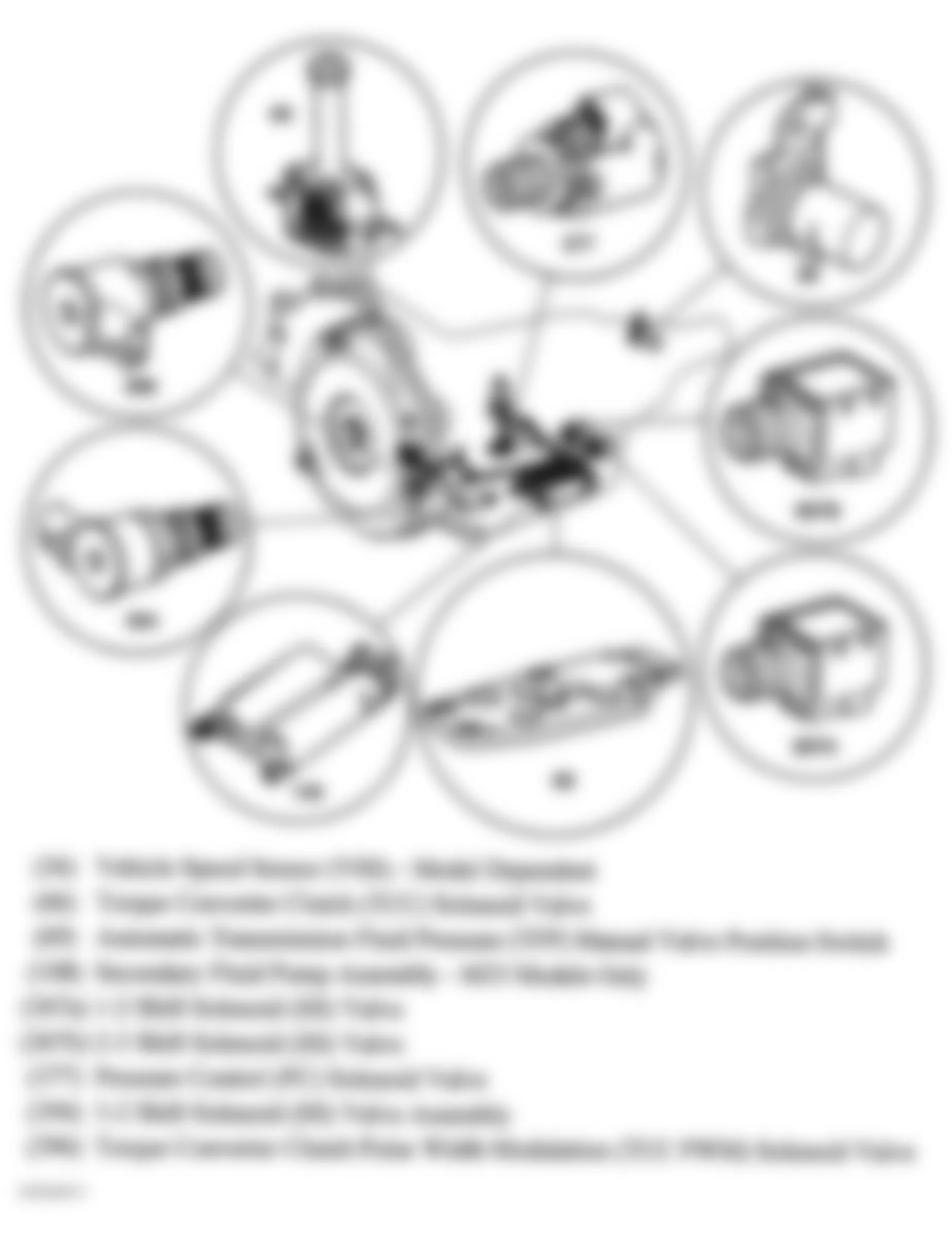
Fig. 53: Hummer H2 2005 - Component Locations - Left Side Of Transmission
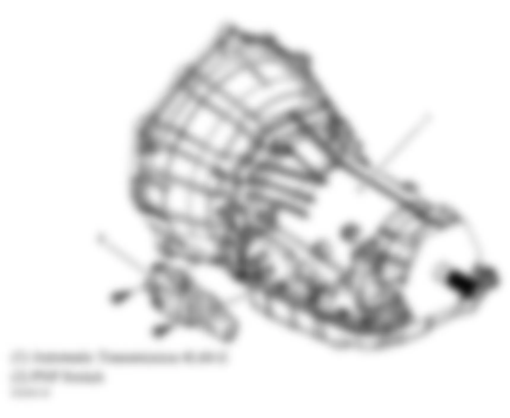
Fig. 54: Hummer H2 2005 - Component Locations - Rear Of Transfer Case
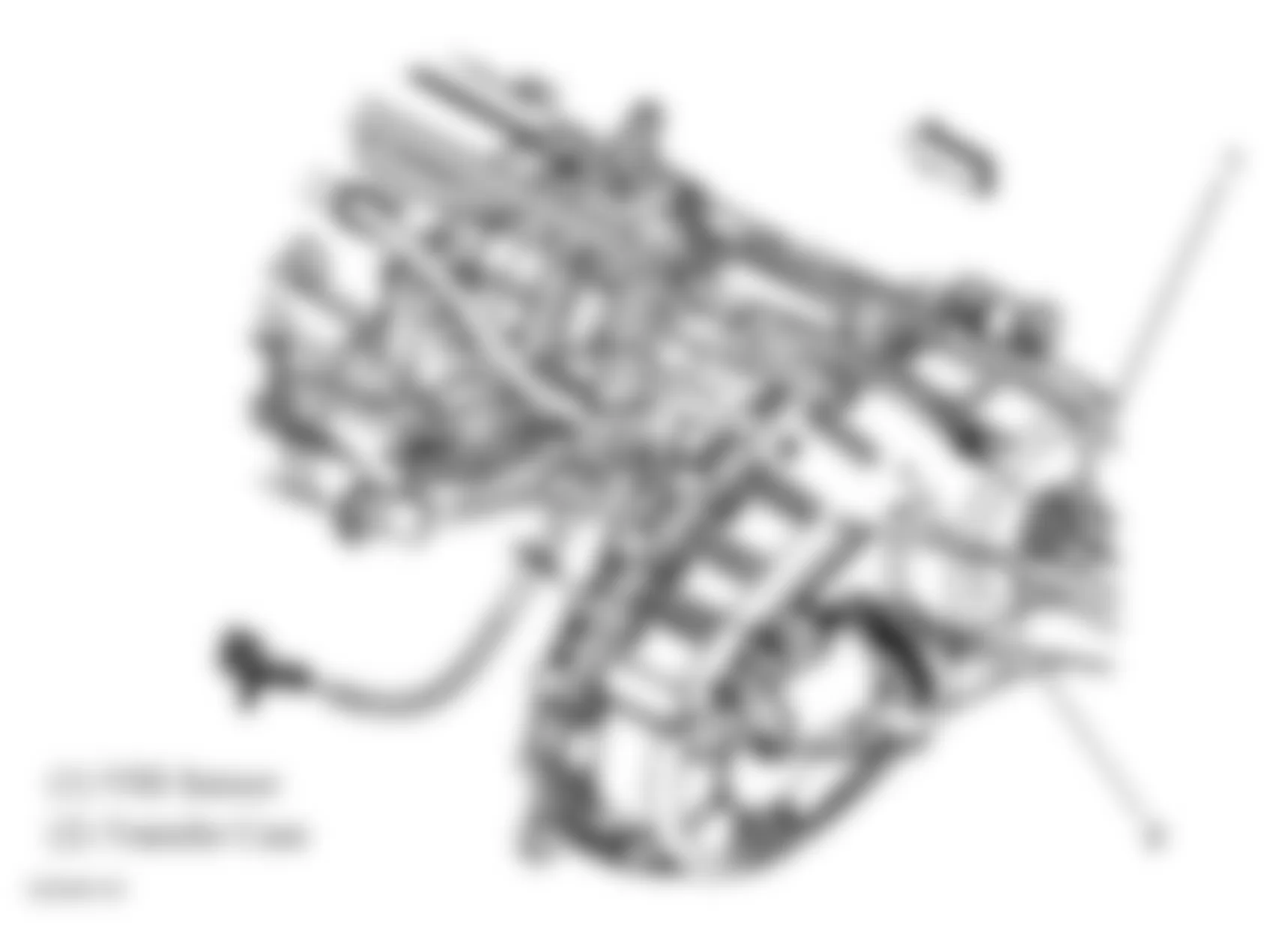
Fig. 55: Hummer H2 2005 - Component Locations - Driver's Seat
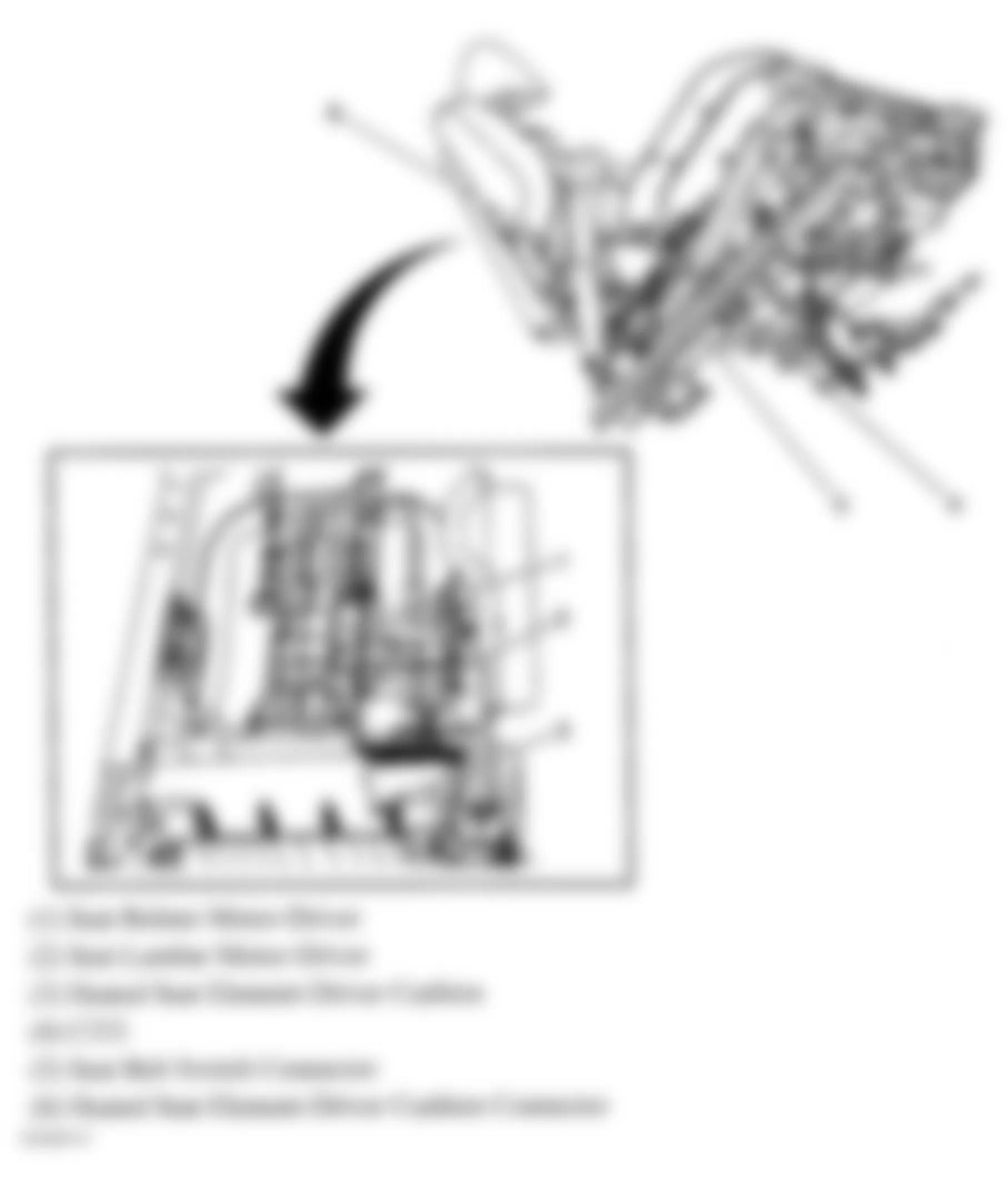
Fig. 56: Hummer H2 2005 - Component Locations - SIR Components (1 Of 2)
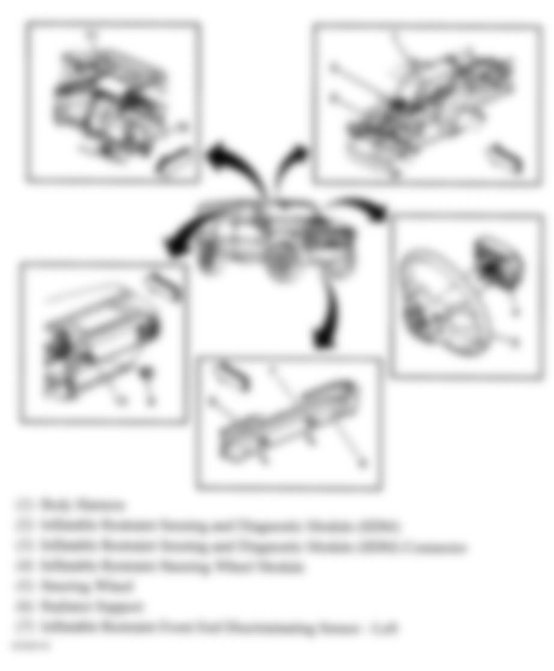
Fig. 57: Hummer H2 2005 - Component Locations - SIR Components (2 Of 2)

Fig. 58: Hummer H2 2005 - Component Locations - SIR Components
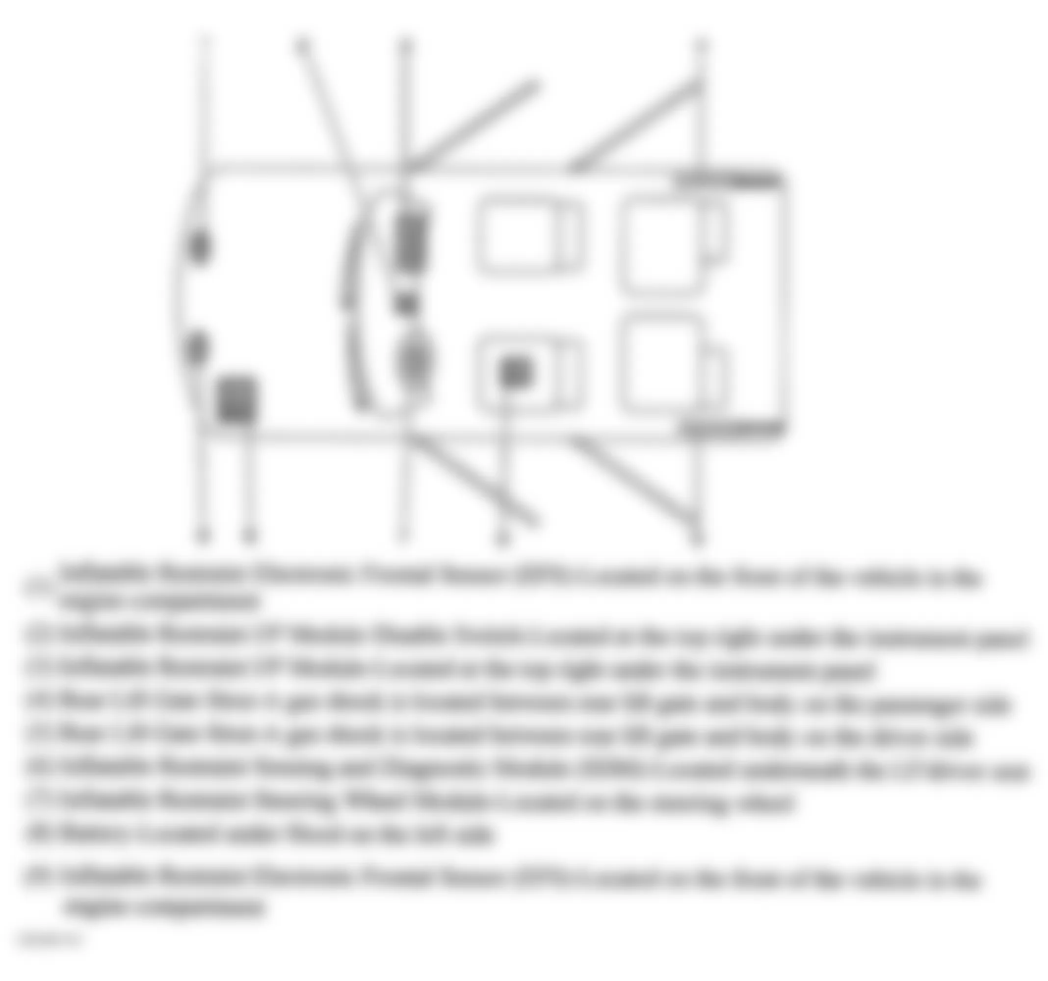
Fig. 59: Hummer H2 2005 - Component Locations - Front Of Roof
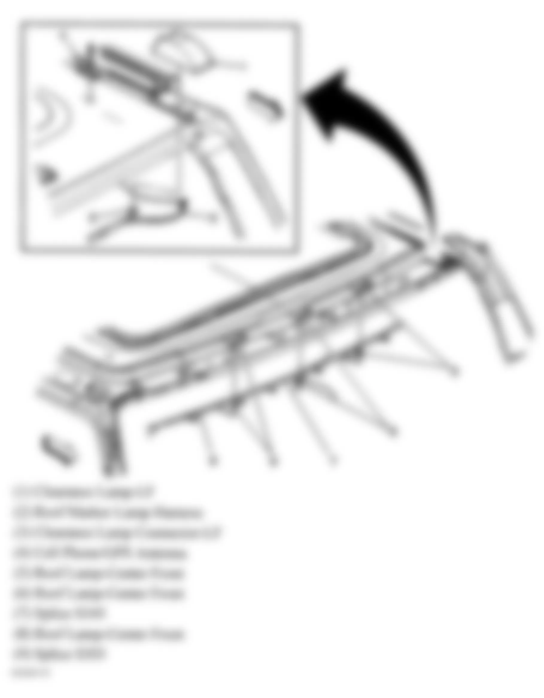
Fig. 60: Hummer H2 2005 - Component Locations - Top Of Left "B" Pillar
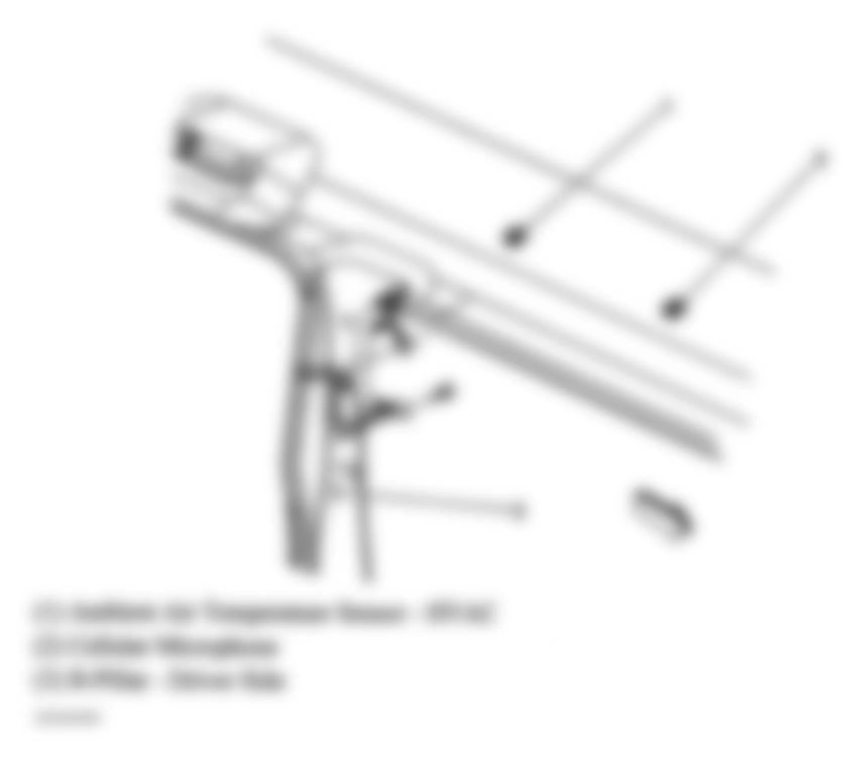
Fig. 61: Hummer H2 2005 - Component Locations - Center Of Dash
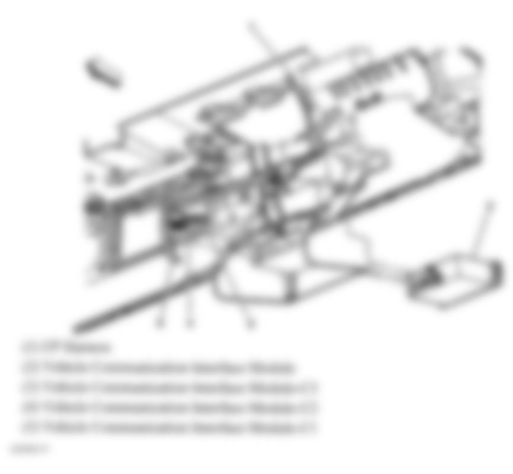
Fig. 62: Hummer H2 2005 - Component Locations - Steering Wheel
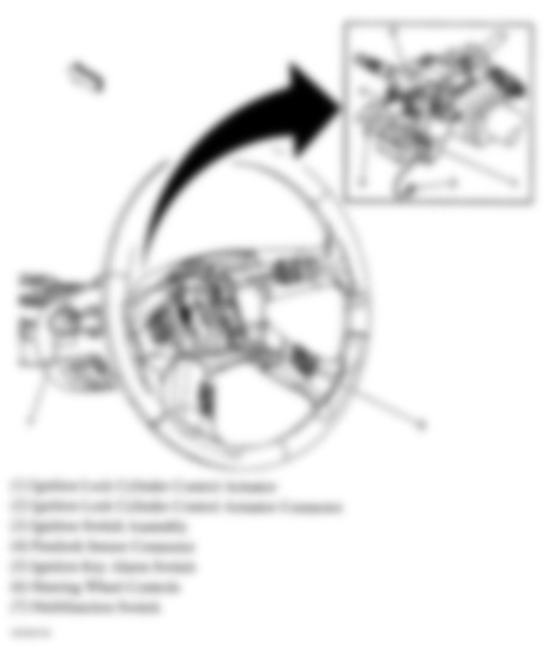
Fig. 63: Hummer H2 2005 - Component Locations - Front Floor Console & Headliner
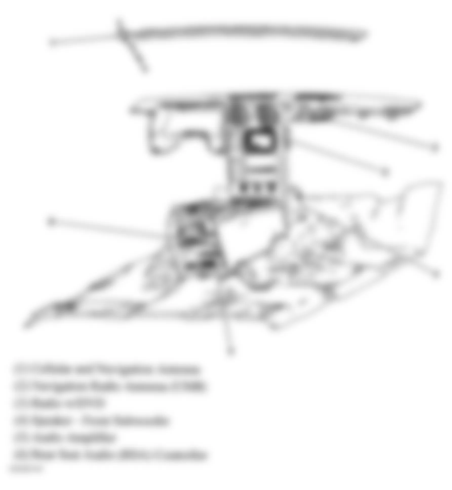
Fig. 64: Hummer H2 2005 - Component Locations - Passenger's Door
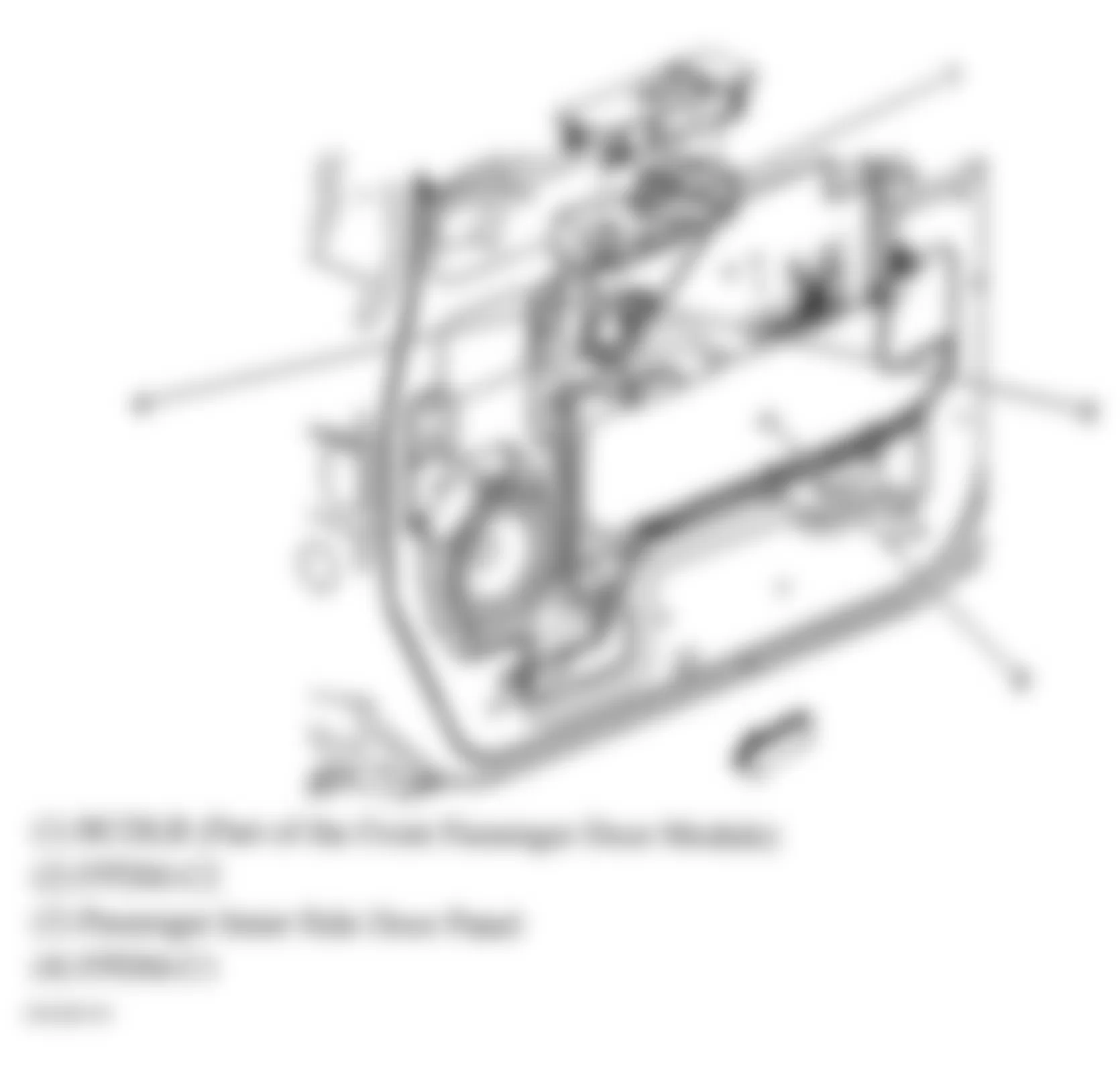
Fig. 65: Hummer H2 2005 - Component Locations - Driver's Door
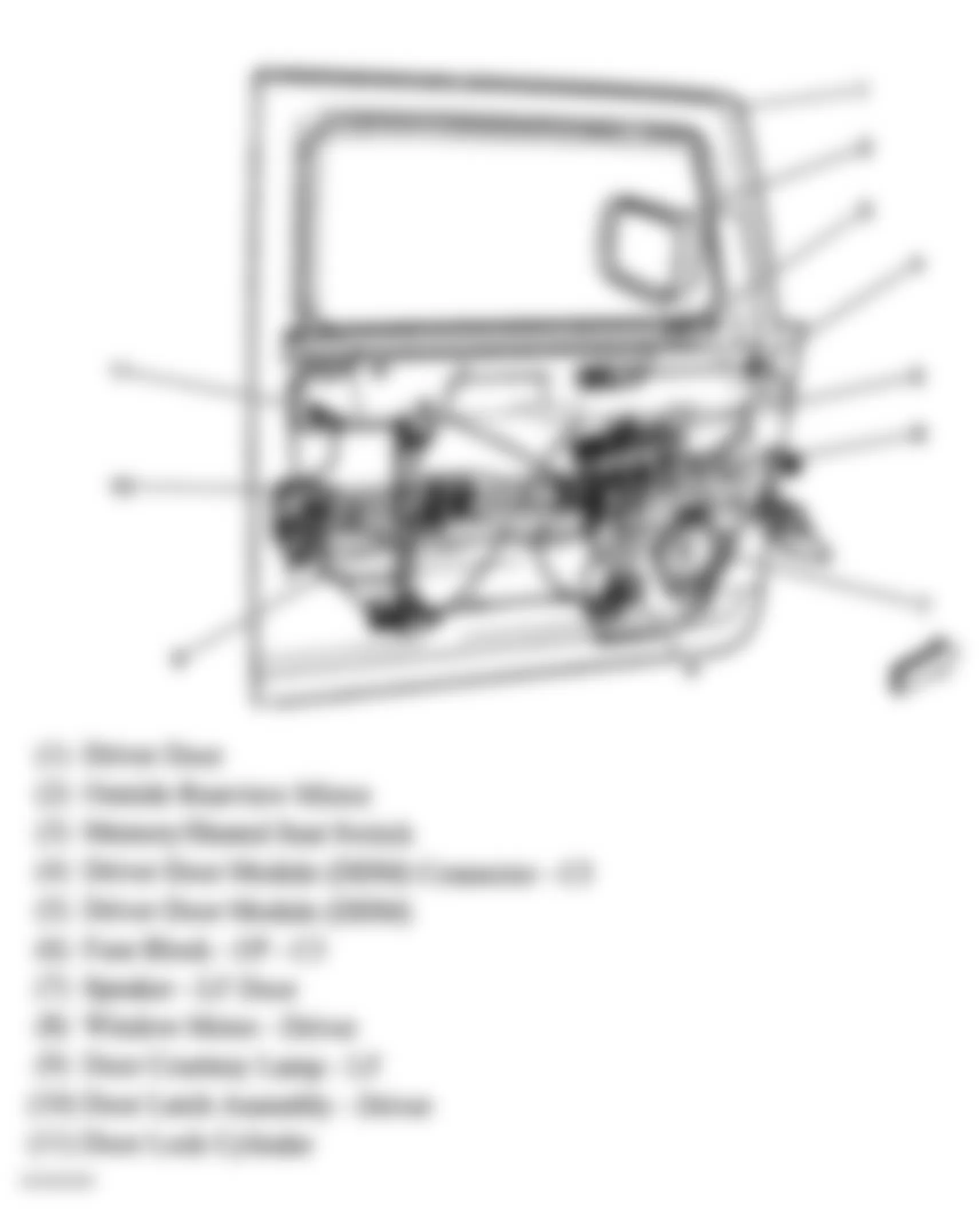
Fig. 66: Hummer H2 2005 - Component Locations - Passenger's Door
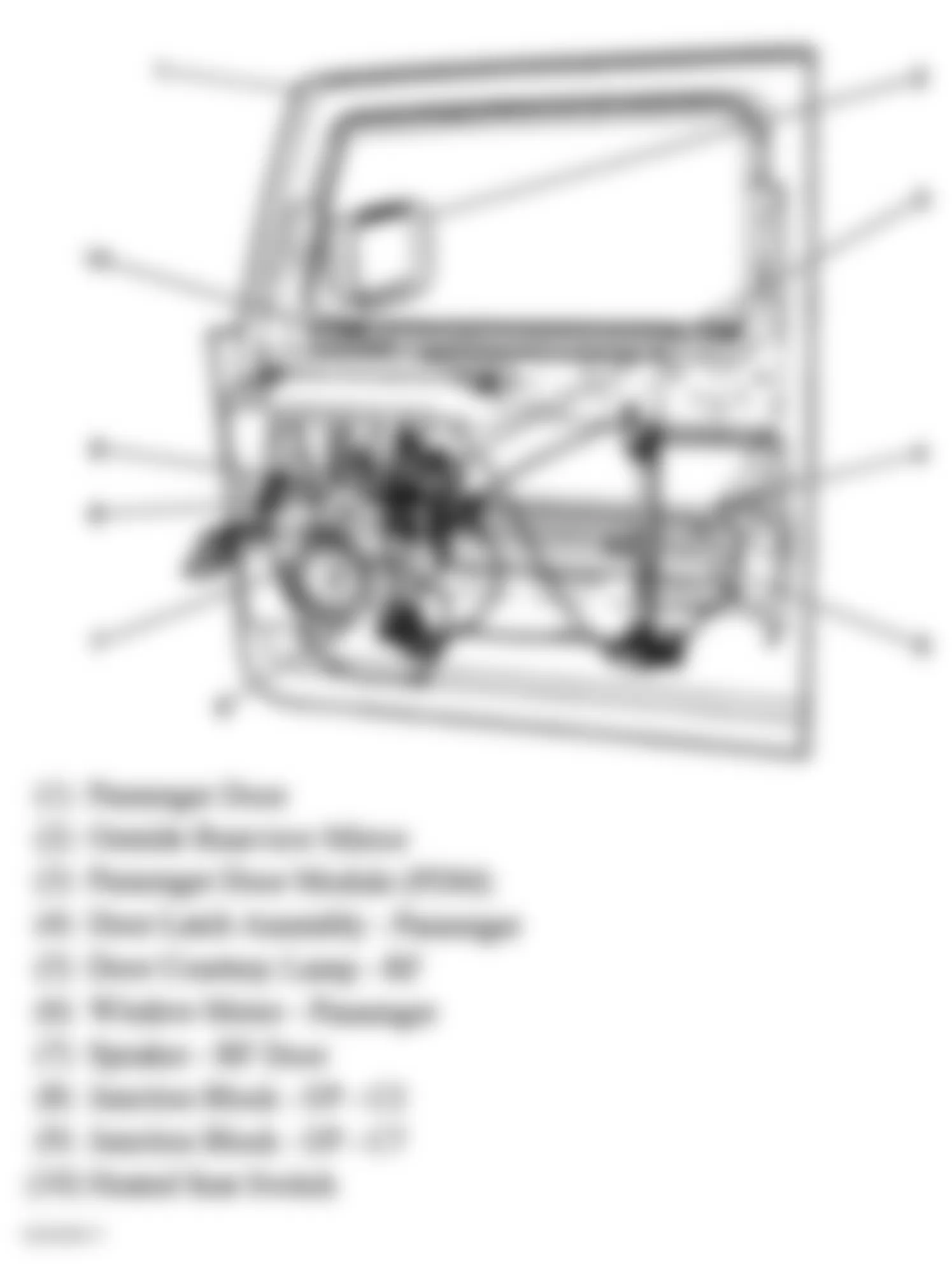
Fig. 67: Hummer H2 2005 - Component Locations - Left Rear Door
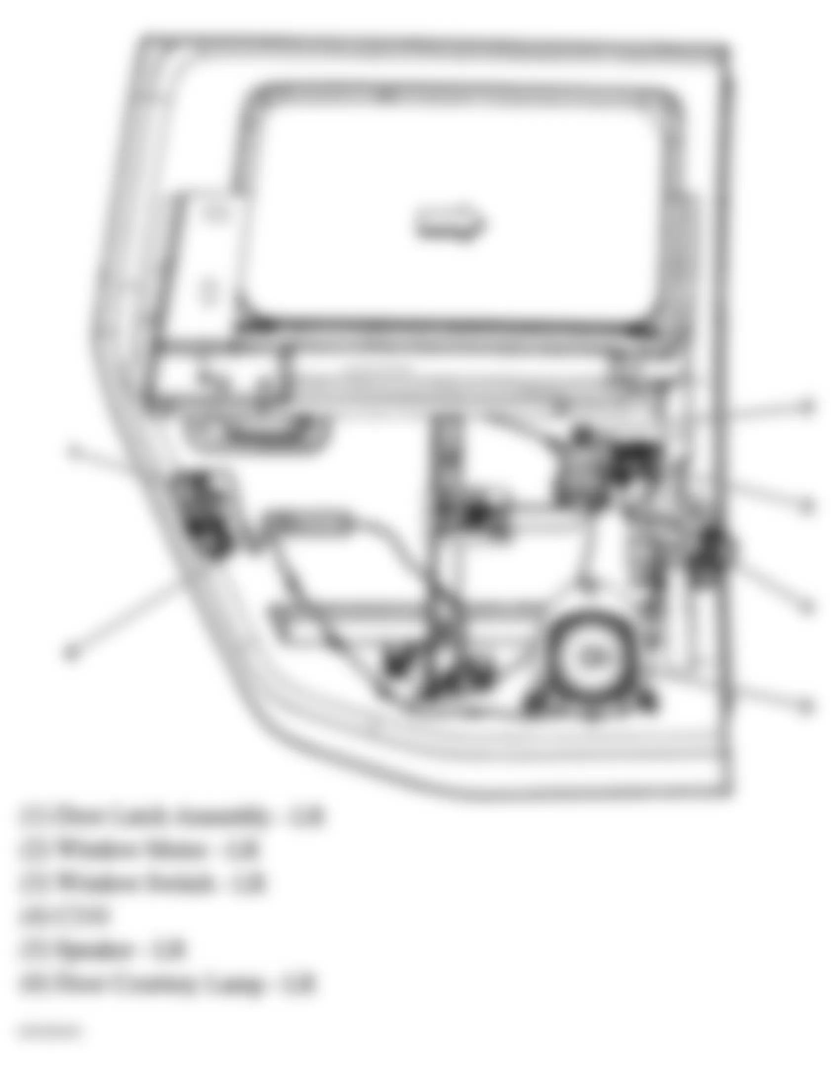
Fig. 68: Hummer H2 2005 - Component Locations - Right "B" Pillar
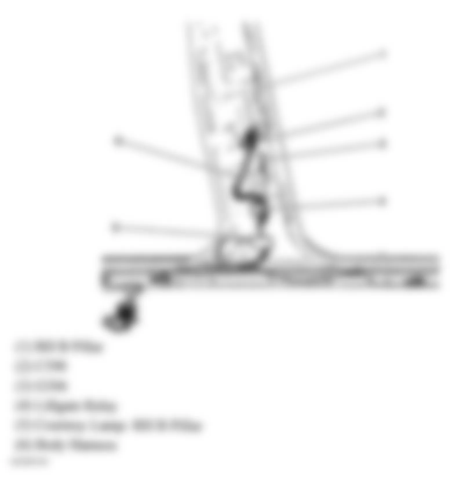
Fig. 69: Hummer H2 2005 - Component Locations - Liftgate
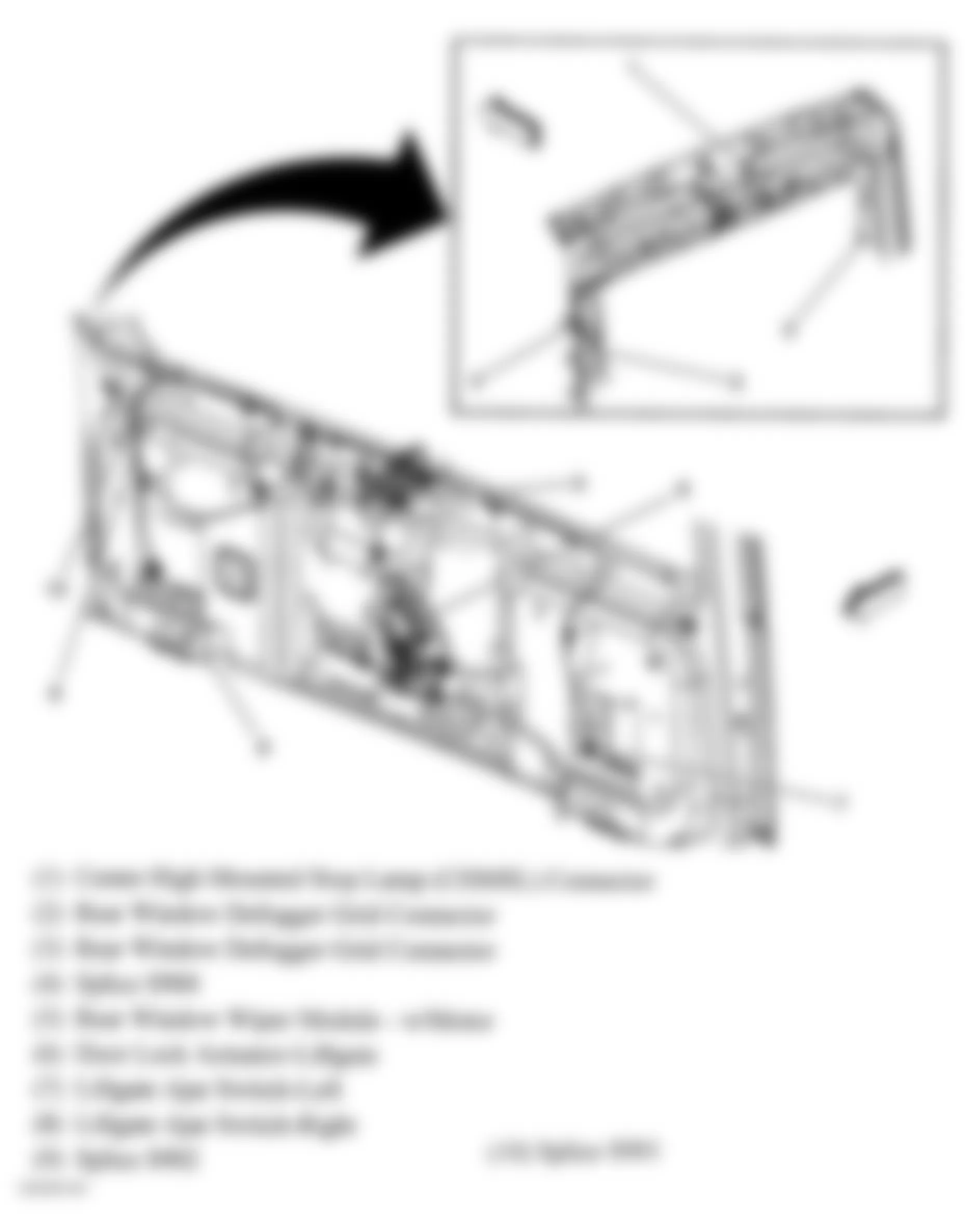
Fig. 70: Hummer H2 2005 - Component Locations - Front Of Vehicle
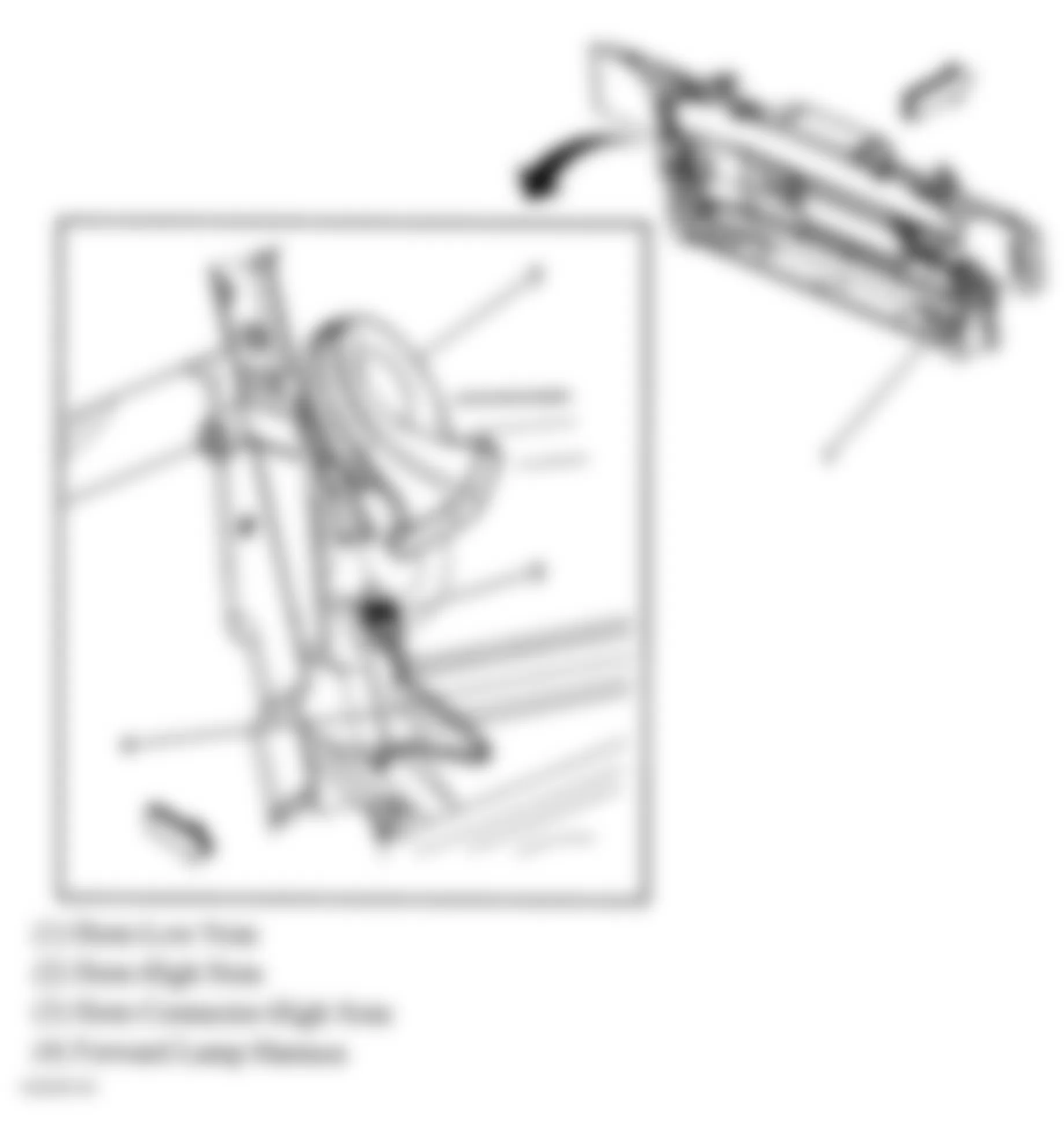
Fig. 71: Hummer H2 2005 - Component Locations - Left Side Of Engine
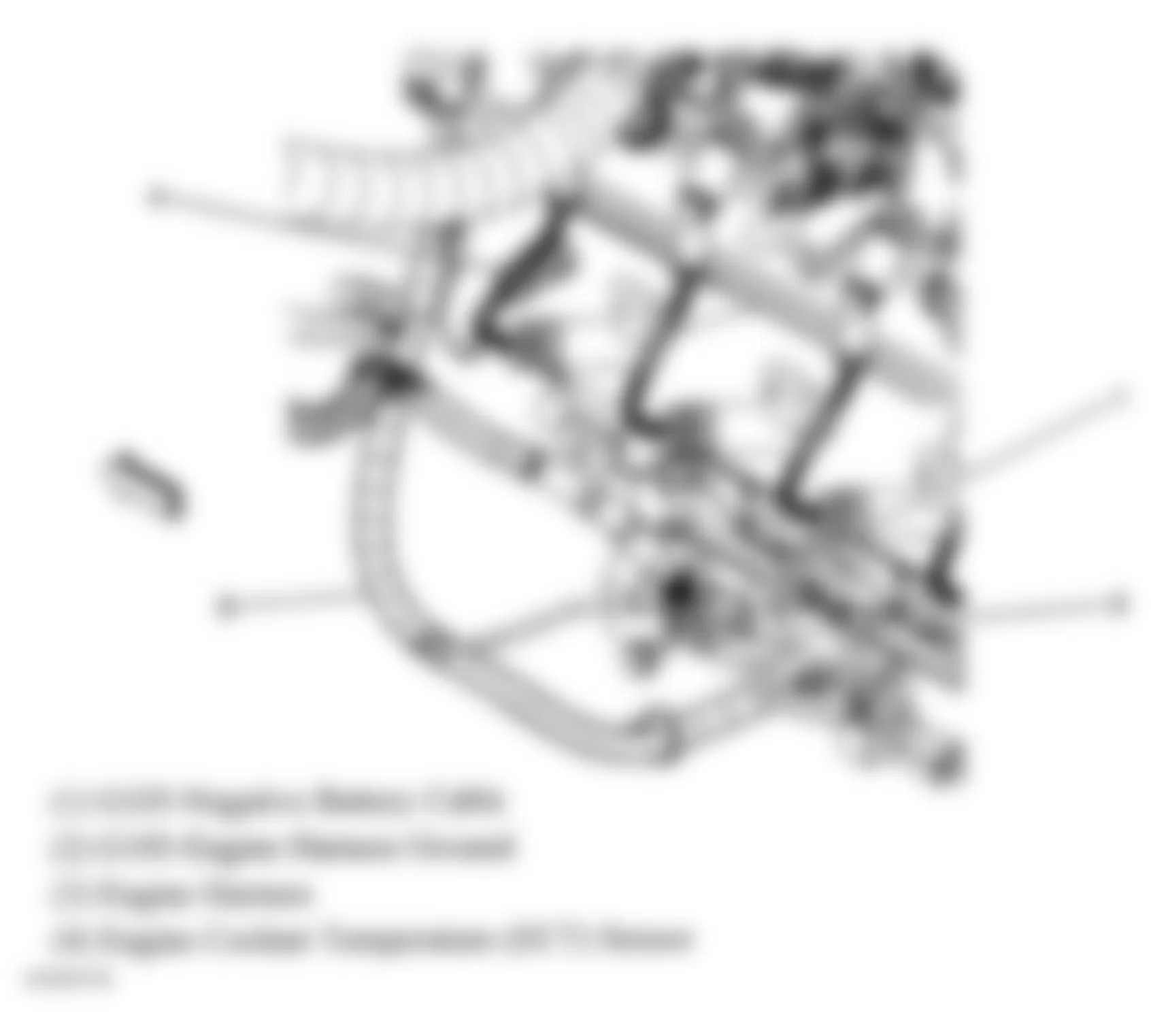
Fig. 72: Hummer H2 2005 - Component Locations - Lower Right Side Of Engine
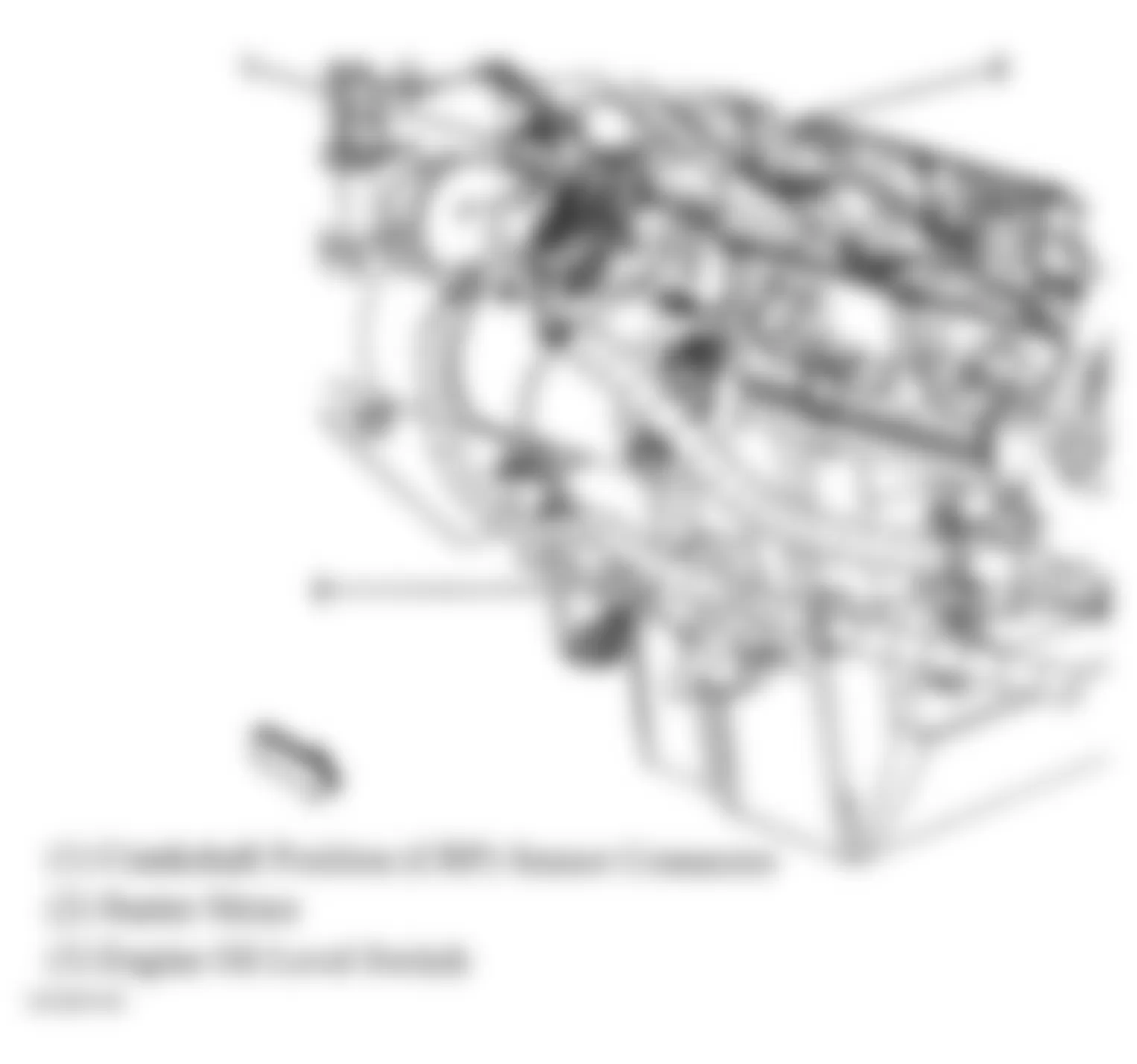
Fig. 73: Hummer H2 2005 - Component Locations - Upper Left Side Of Dash
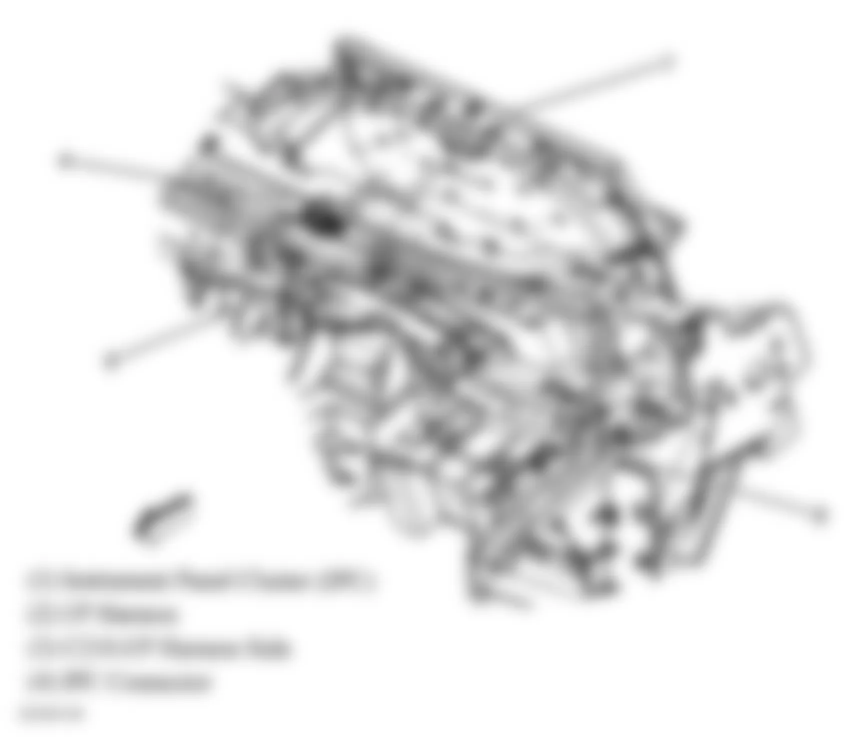
Fig. 74: Hummer H2 2005 - Component Locations - Top Of Fuel Tank
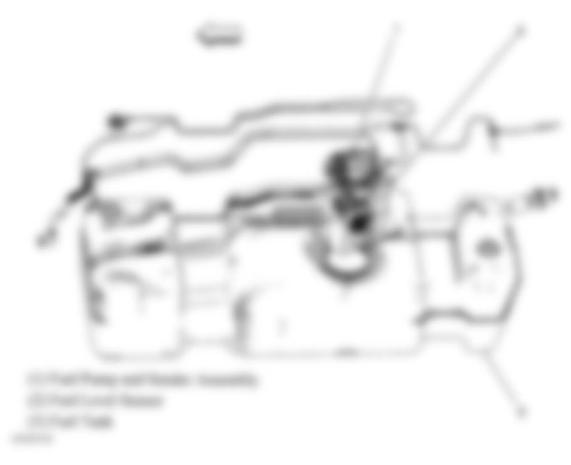
Fig. 75: Hummer H2 2005 - Component Locations - Front Of Roof
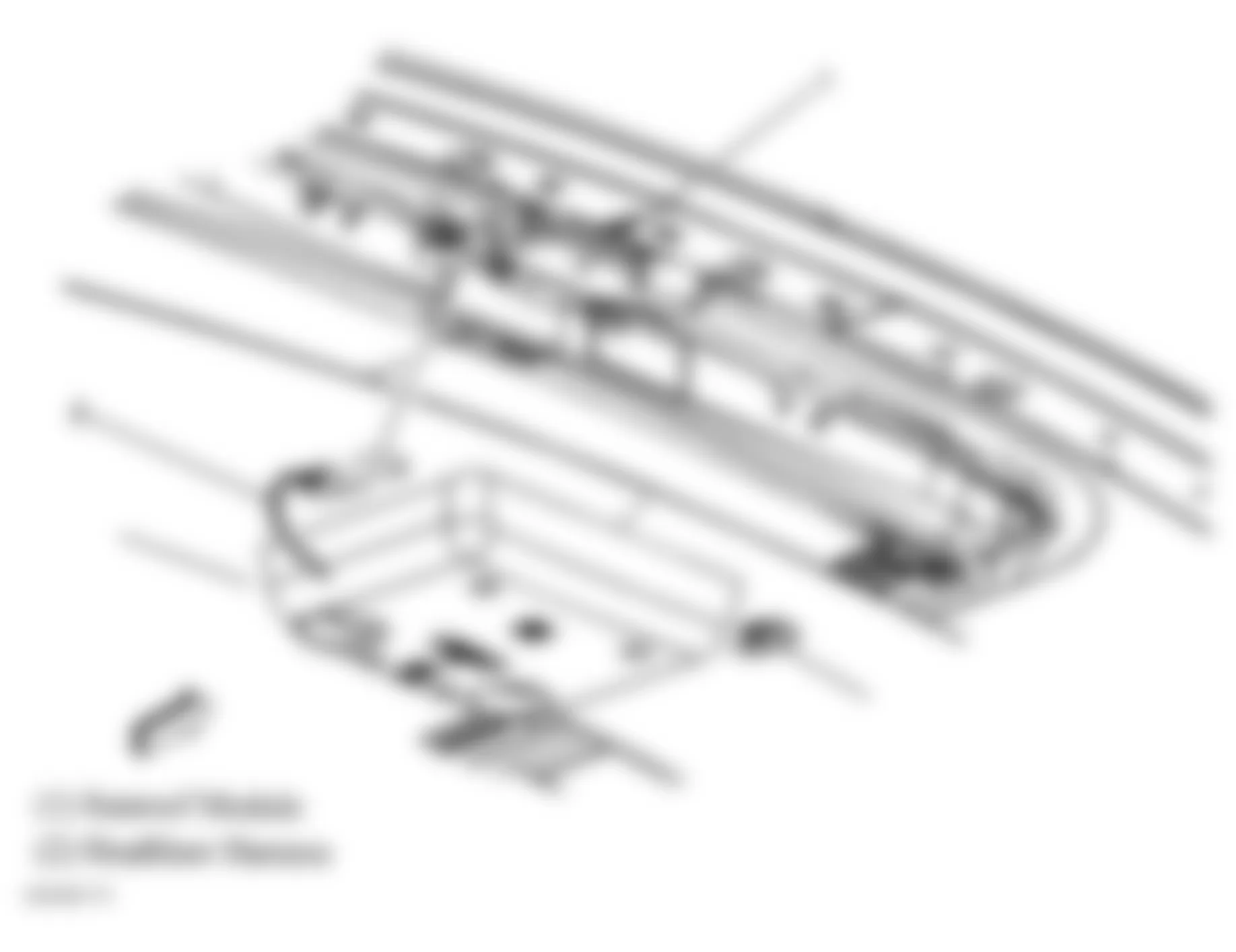
Fig. 76: Hummer H2 2005 - Component Locations - Left "A" Pillar
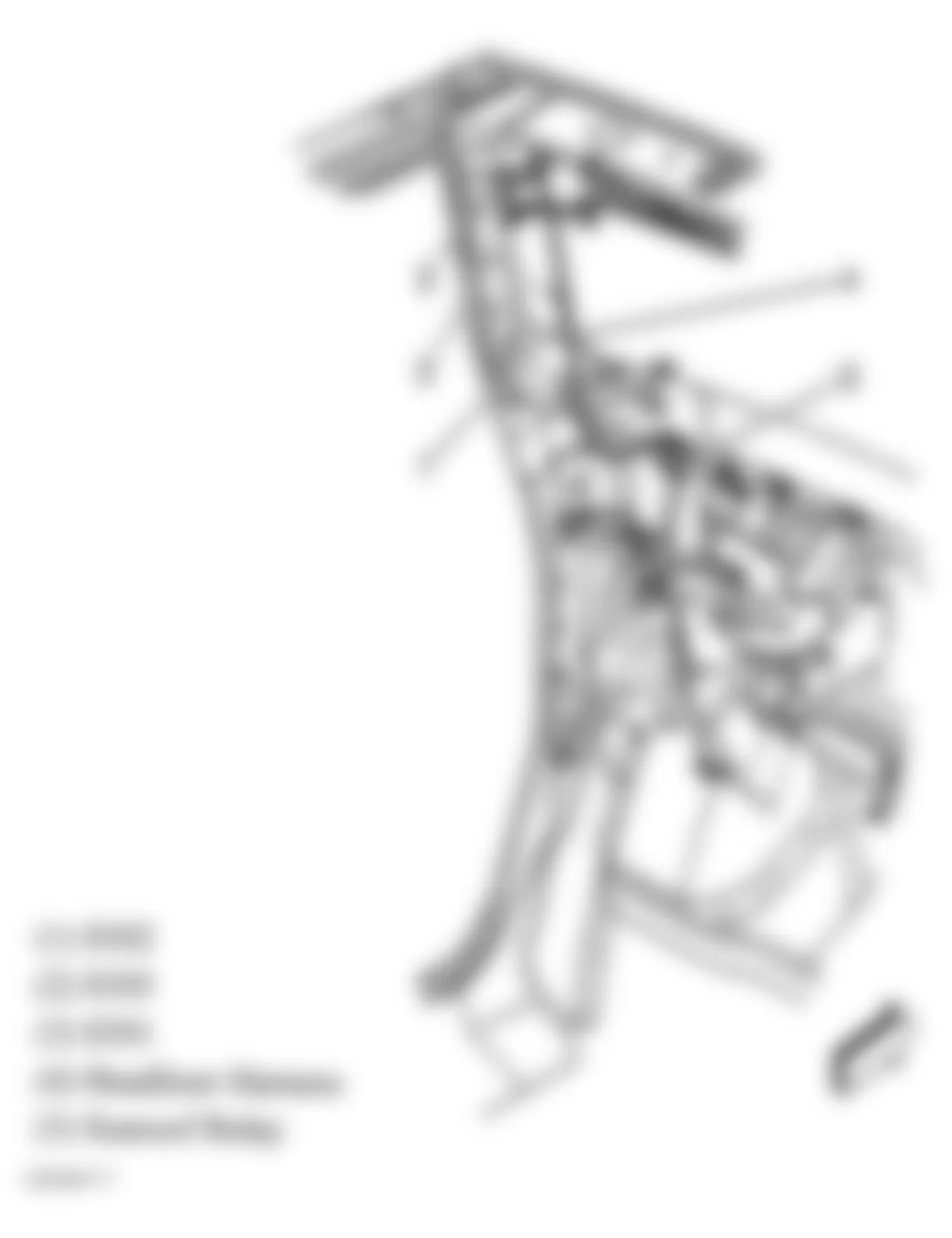
Fig. 77: Hummer H2 2005 - Component Locations - Under Driver Seat
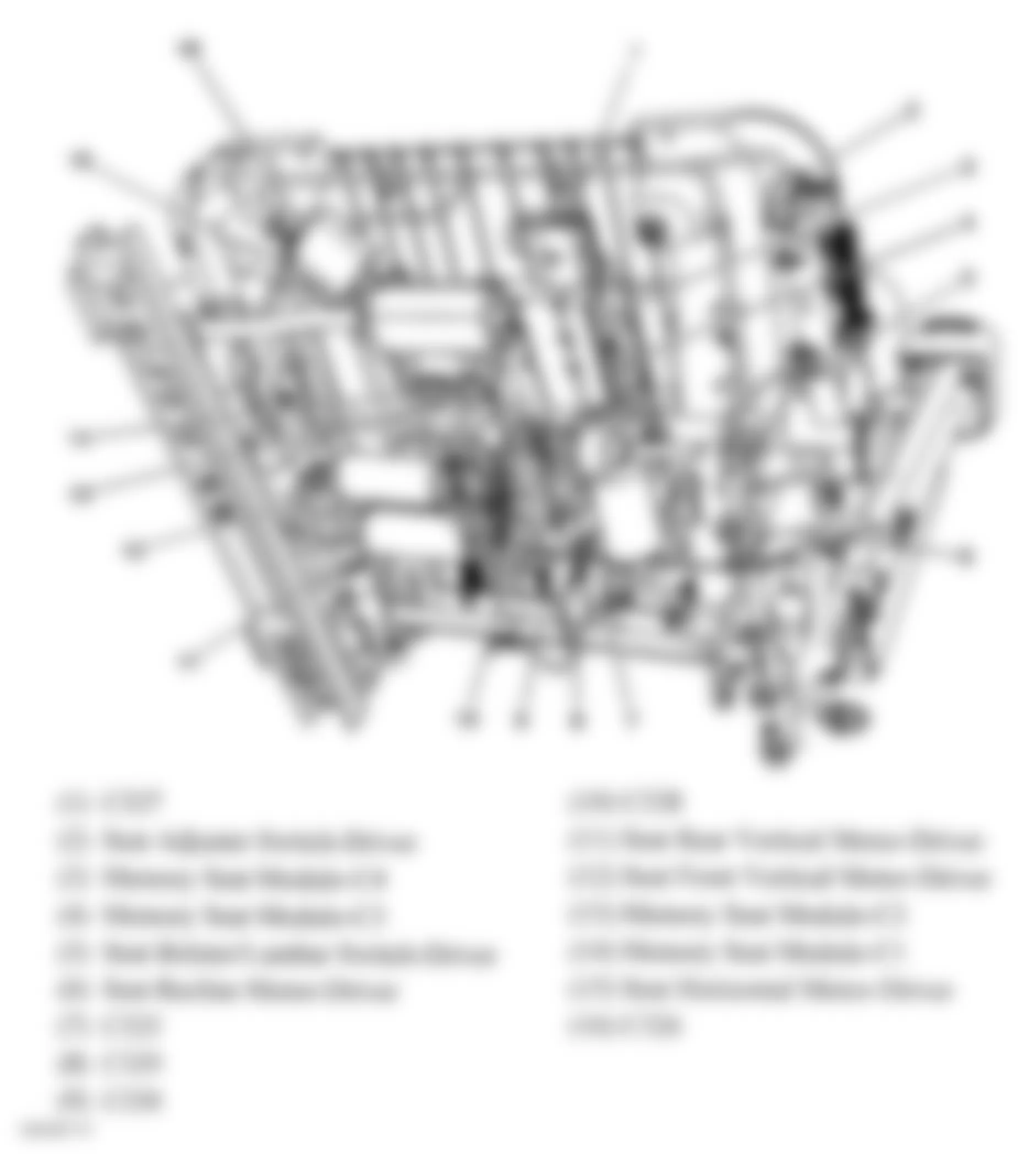
Fig. 78: Hummer H2 2005 - Component Locations - Under Passenger's Seat
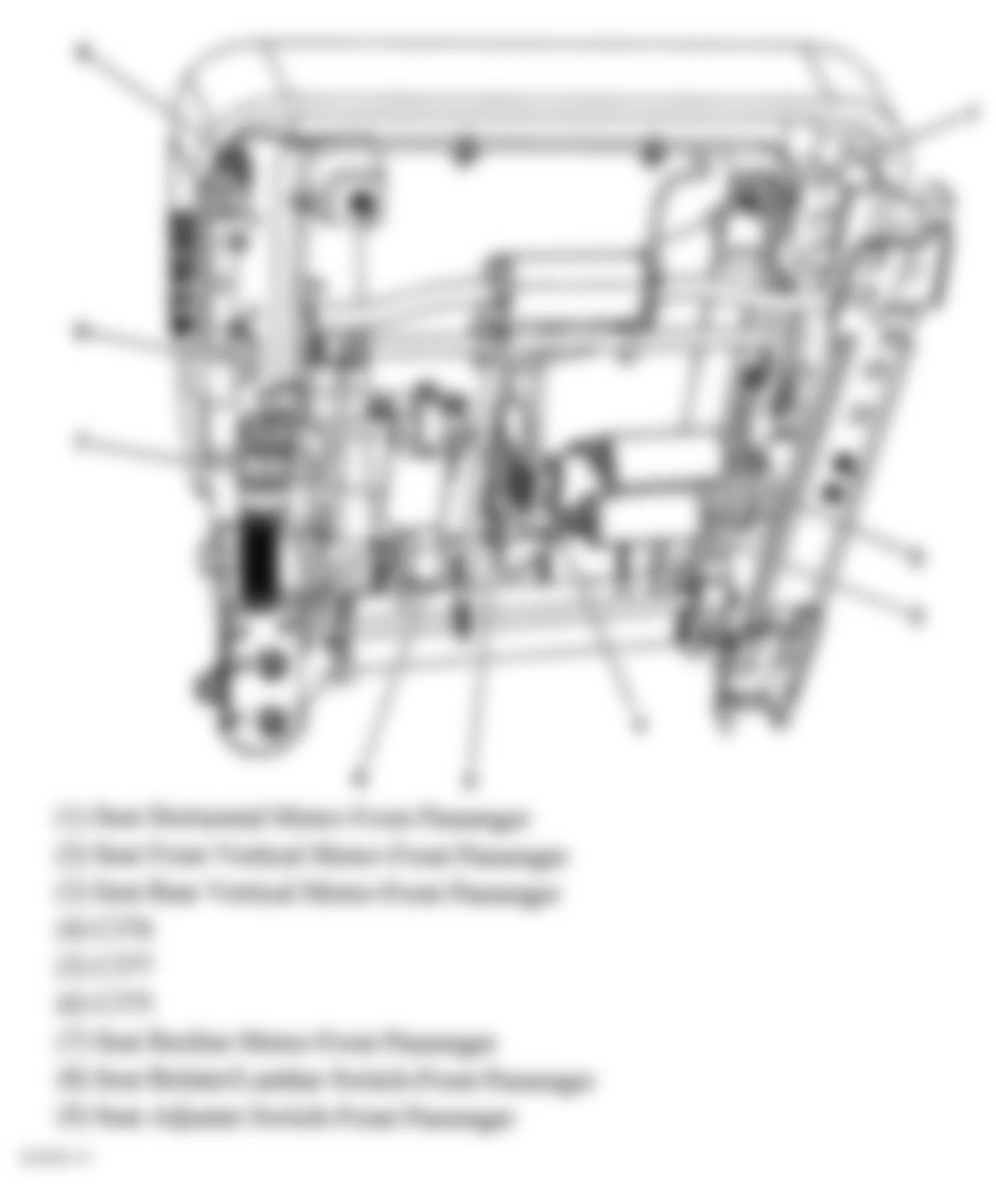
Fig. 79: Hummer H2 2005 - Component Locations - Passenger's Seat
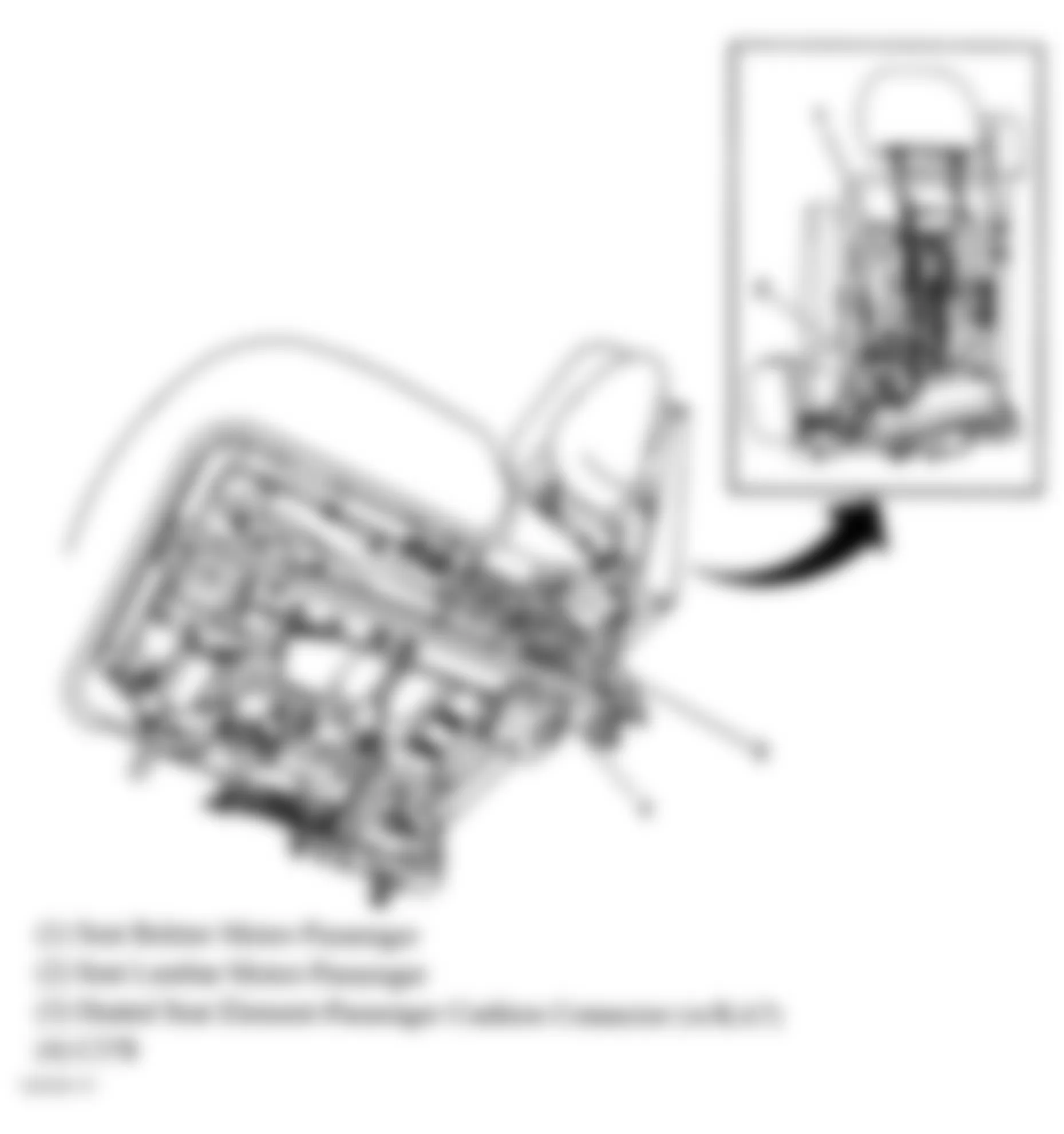
Fig. 80: Hummer H2 2005 - Component Locations - 2nd Row Seats

Fig. 81: Hummer H2 2005 - Component Locations - Wiper/Washer System Components
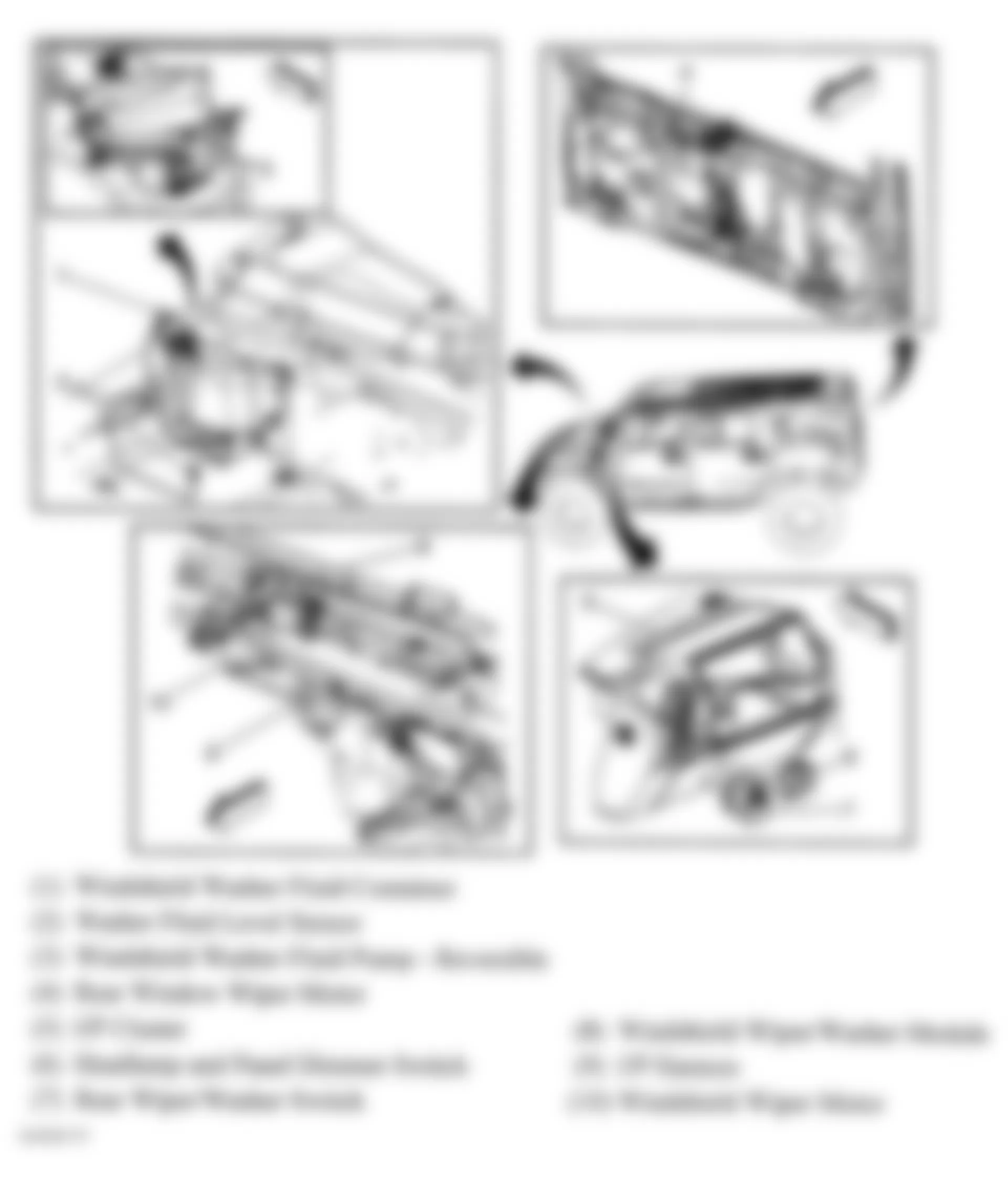
Fig. 82: Hummer H2 2005 - Component Locations - Front Floor Console
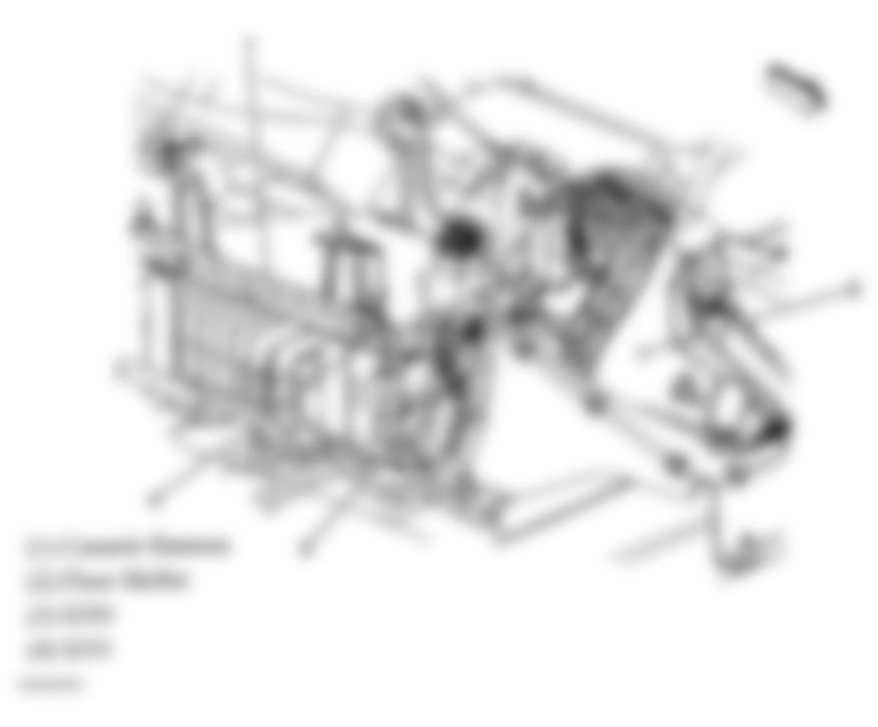
Fig. 83: Hummer H2 2005 - Component Locations - Chassis (1 Of 2)
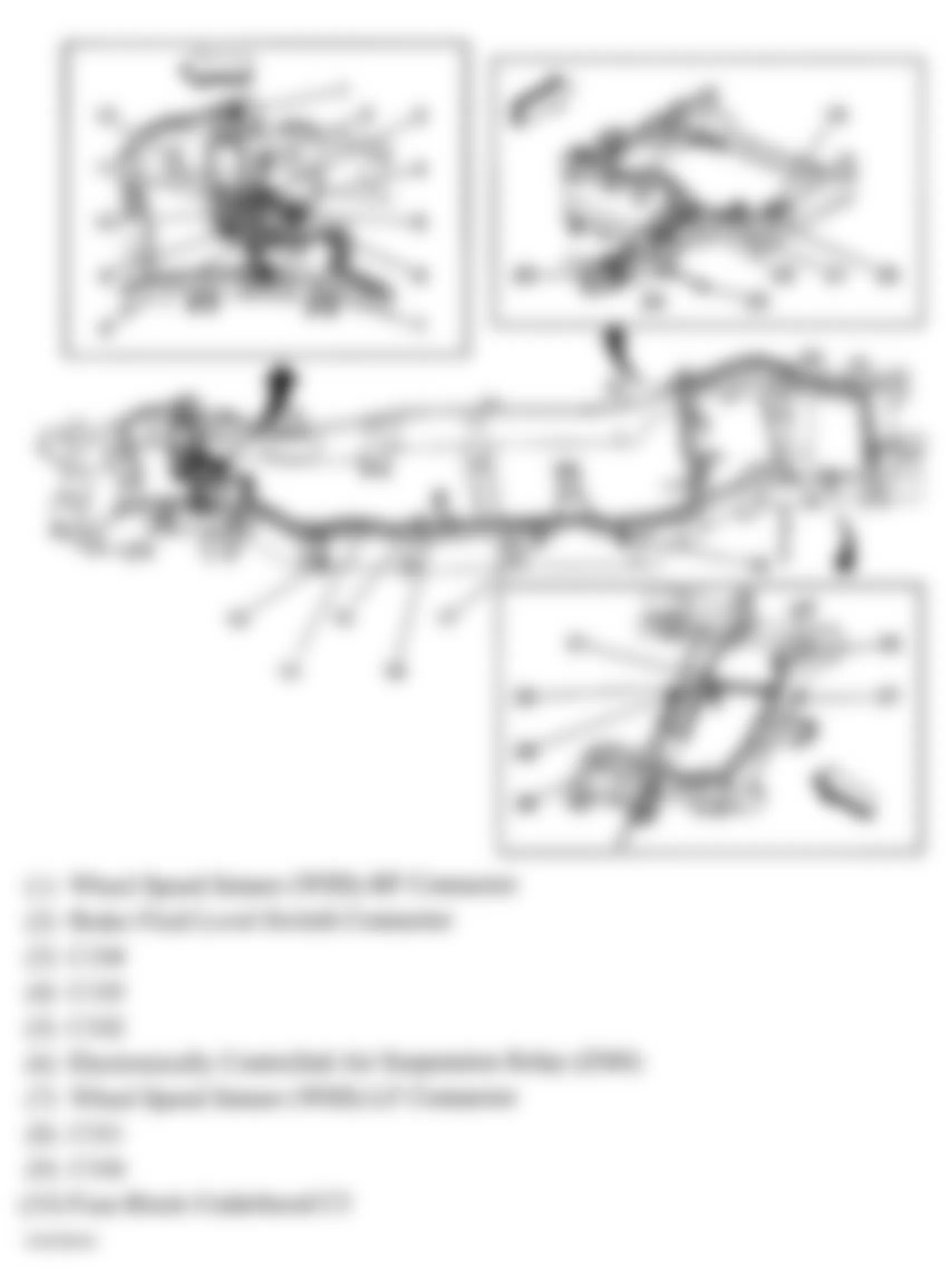
Fig. 84: Hummer H2 2005 - Component Locations - Chassis (2 Of 2)
Fig. 85: Hummer H2 2005 - Component Locations - Right Kick Panel
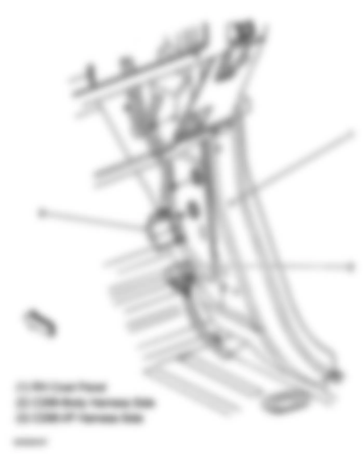
Fig. 86: Hummer H2 2005 - Component Locations - Engine (1 Of 2)
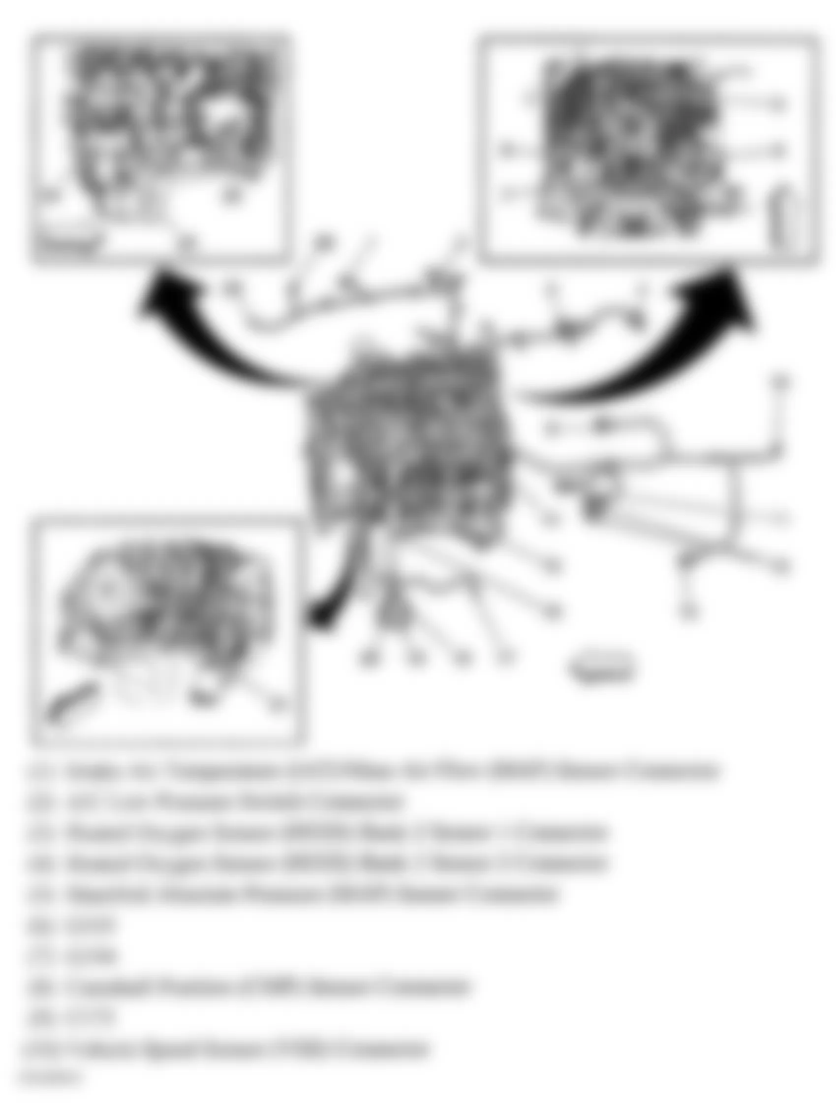
Fig. 87: Hummer H2 2005 - Component Locations - Engine (2 Of 2)
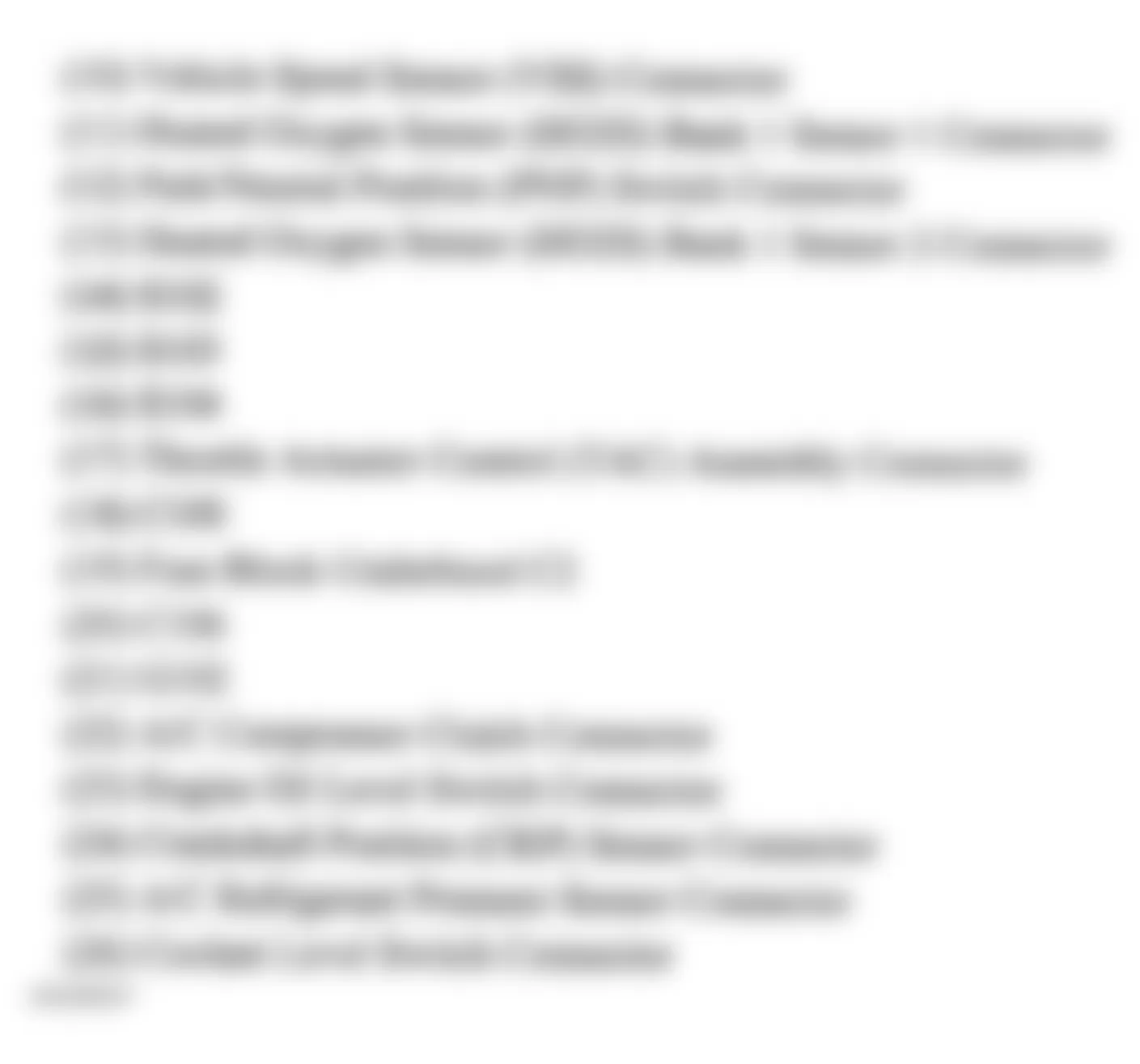
Fig. 88: Hummer H2 2005 - Component Locations - Left Front Of Engine Compartment
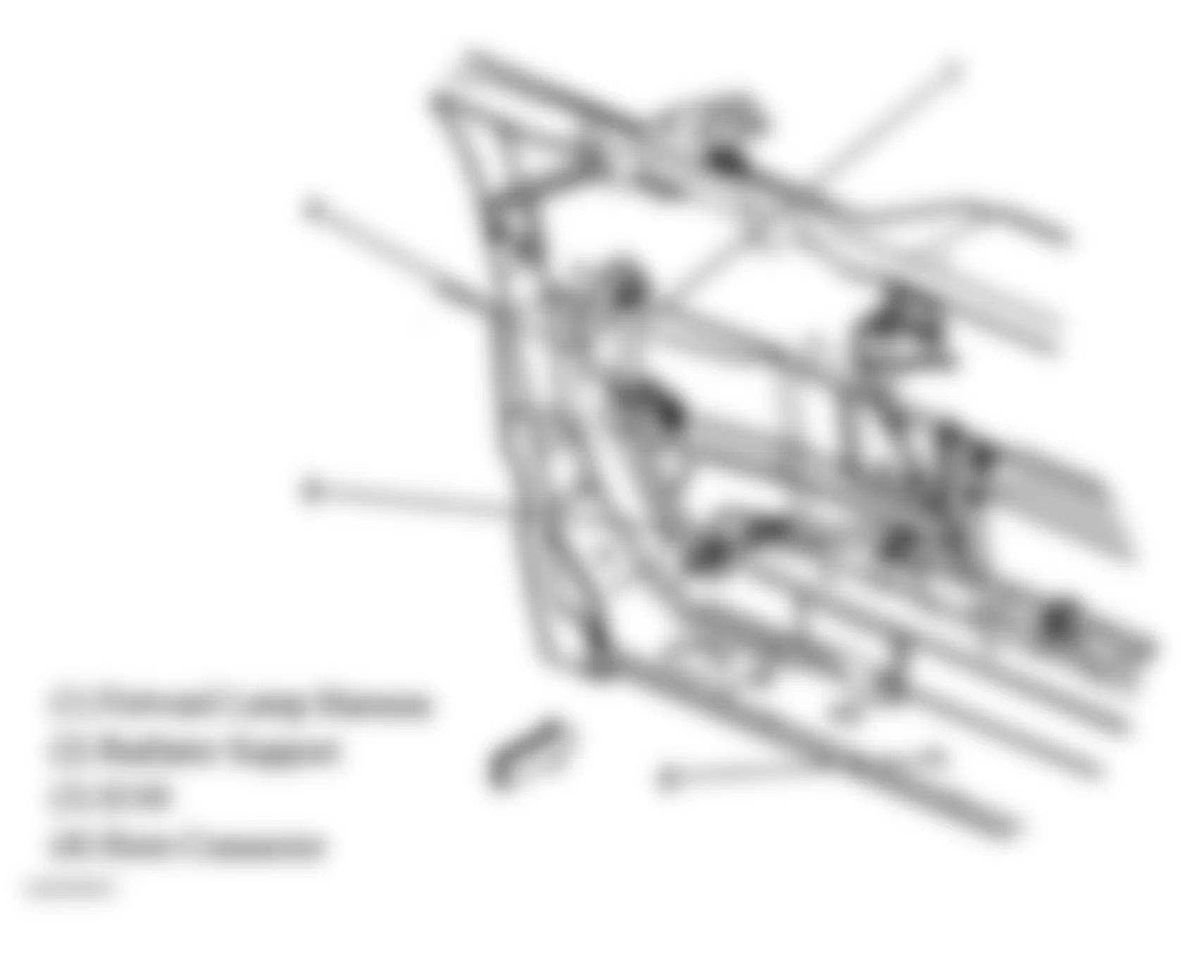
Fig. 89: Hummer H2 2005 - Component Locations - Right Front Of Engine Compartment
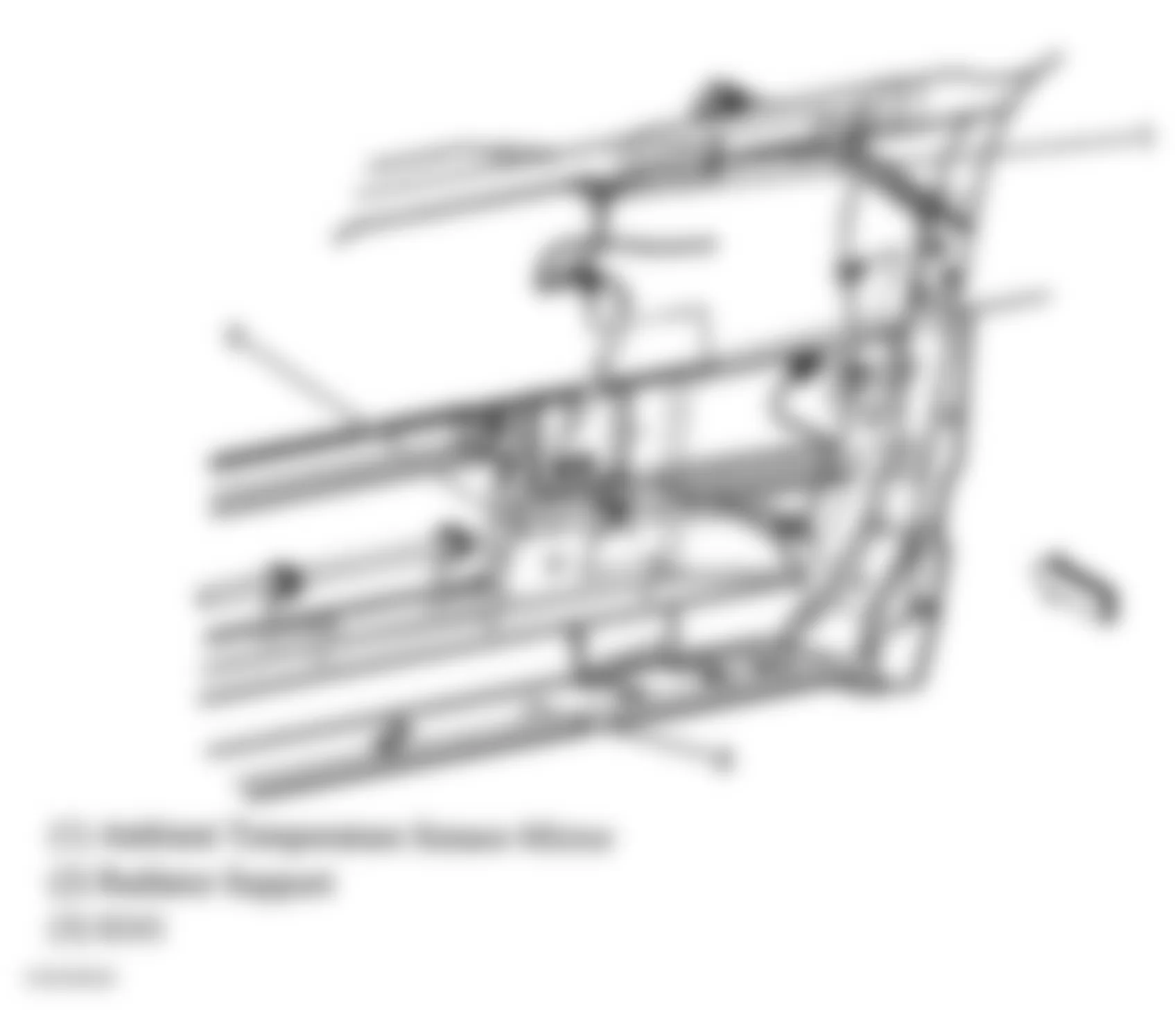
Fig. 90: Hummer H2 2005 - Component Locations - Left Side Of Engine Compartment
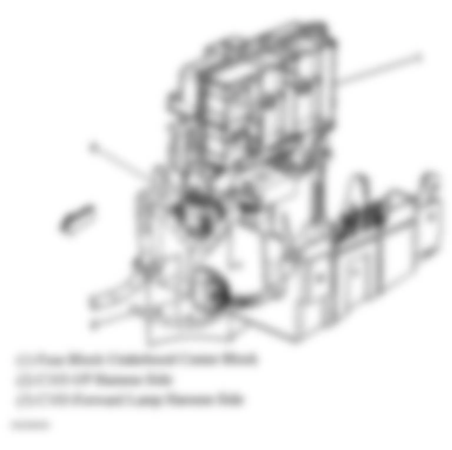
Fig. 91: Hummer H2 2005 - Component Locations - Front Floor Console
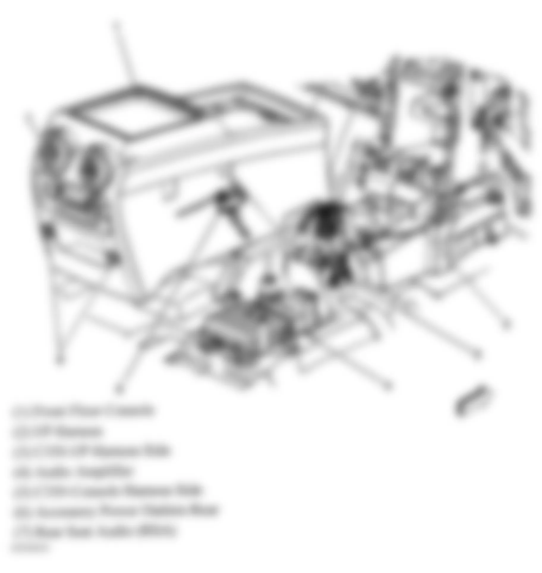
Fig. 92: Hummer H2 2005 - Component Locations - Top Of Liftgate
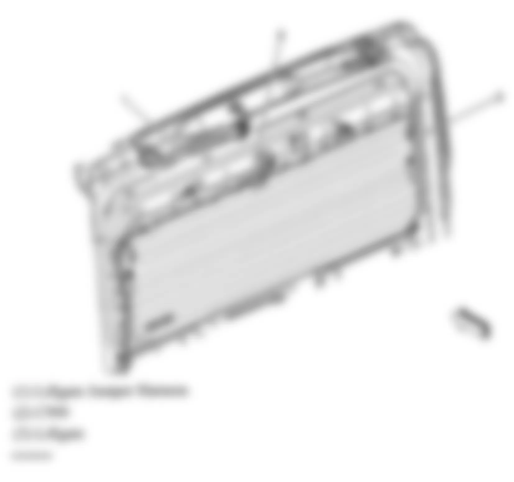
Fig. 93: Hummer H2 2005 - Component Locations - Front Roof Line
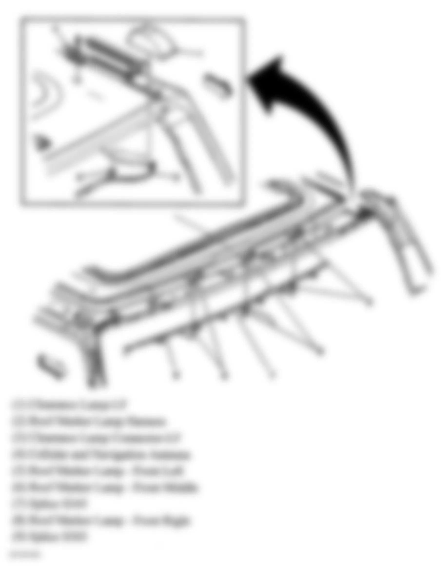
Fig. 94: Hummer H2 2005 - Component Locations - Liftgate
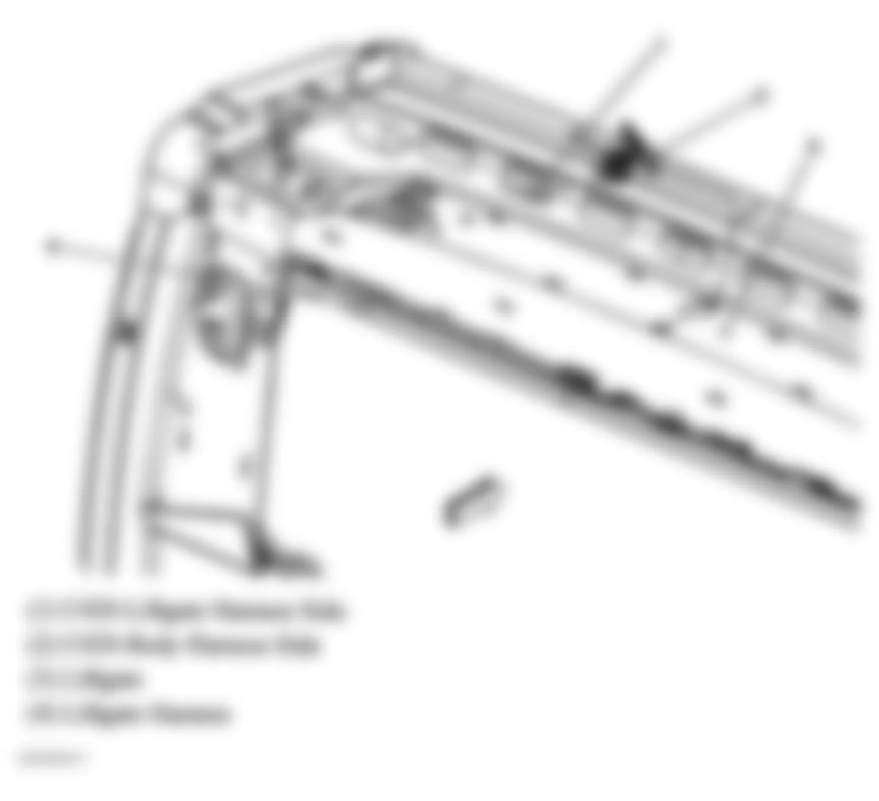
Fig. 95: Hummer H2 2005 - Component Locations - Right Rear Door
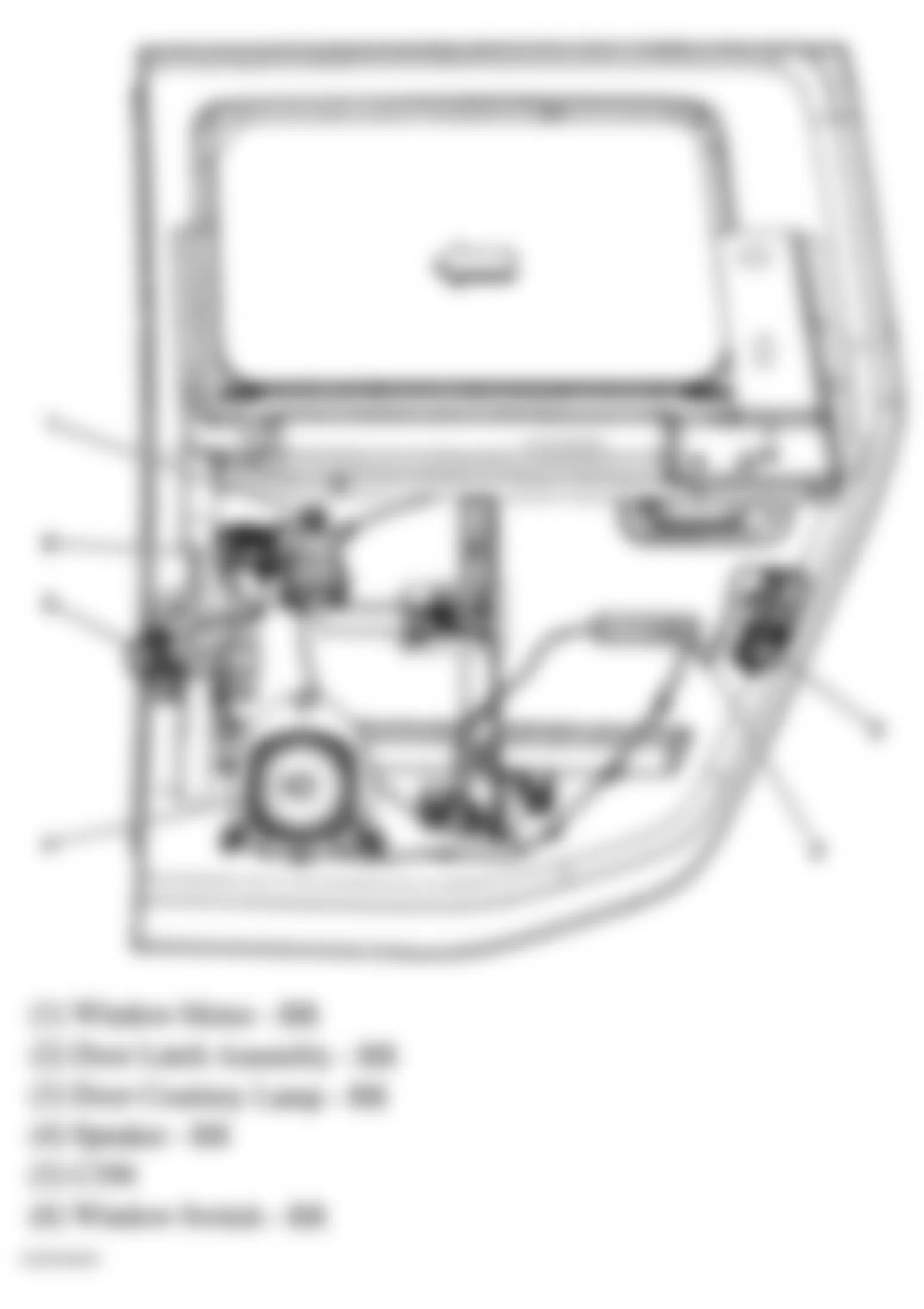
Fig. 96: Hummer H2 2005 - Component Locations - Rear Underside Of Vehicle
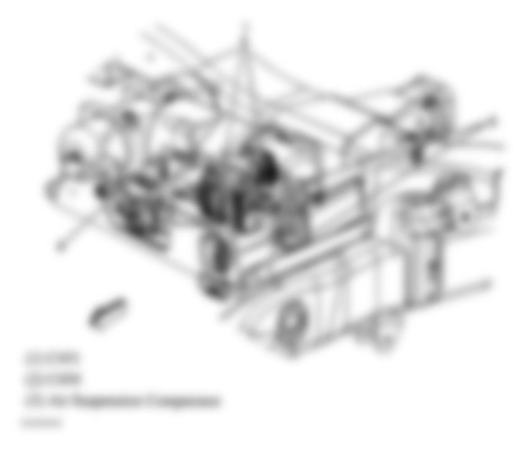
Fig. 97: Hummer H2 2005 - Component Locations - Ground Location (G300)
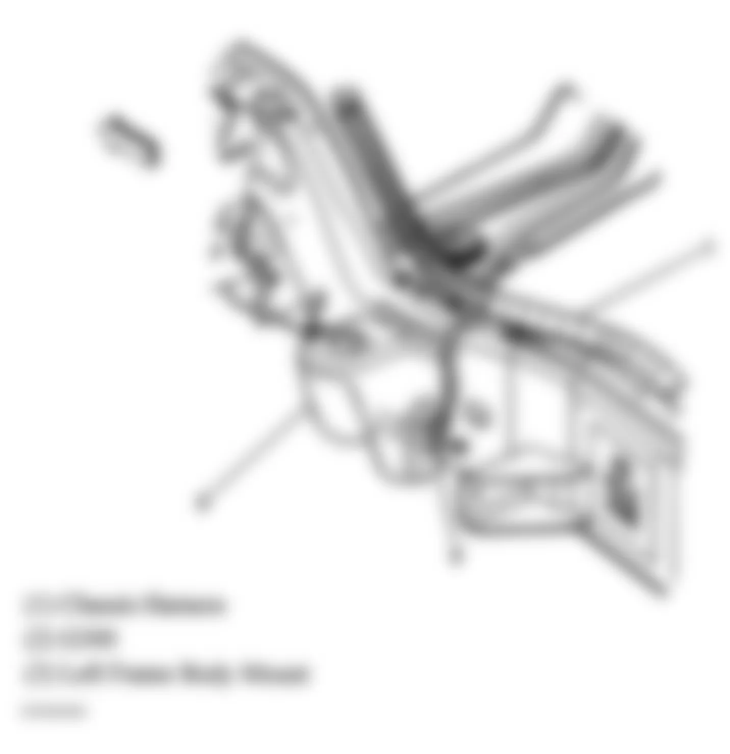
Fig. 98: Hummer H2 2005 - Component Locations - Lower Underside Of Steering Column
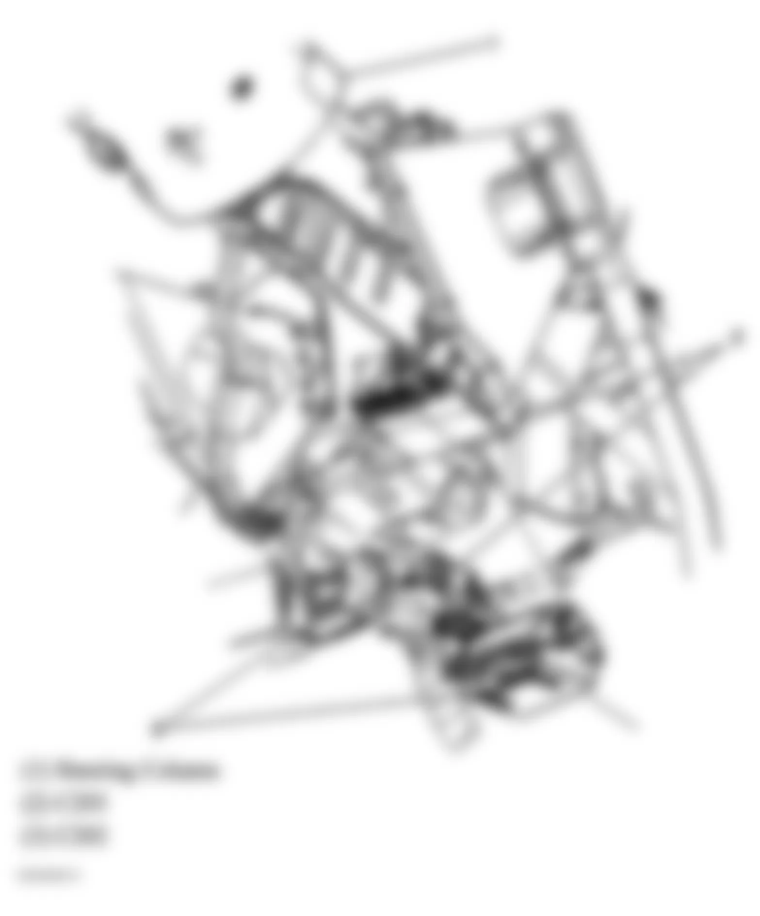
Fig. 99: Hummer H2 2005 - Component Locations - Antenna Locations
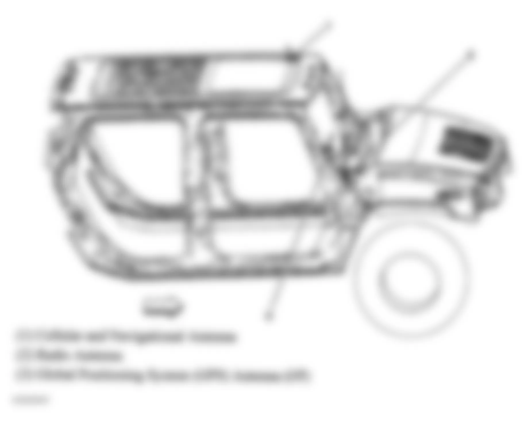
Fig. 100: Hummer H2 2005 - Component Locations - Second Row Heated Seat Components
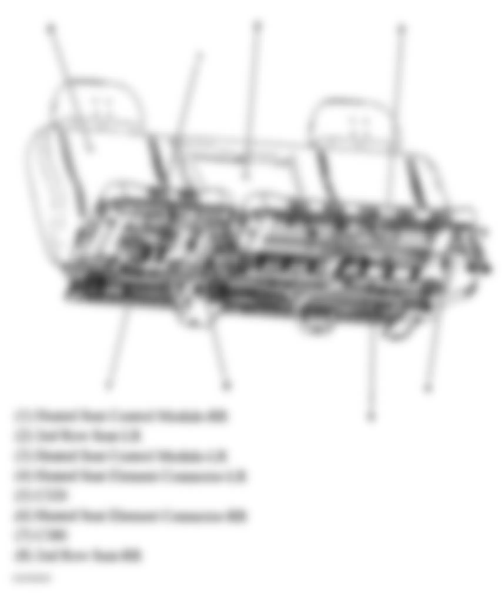
Fig. 101: Hummer H2 2005 - Component Locations - Instrument Panel
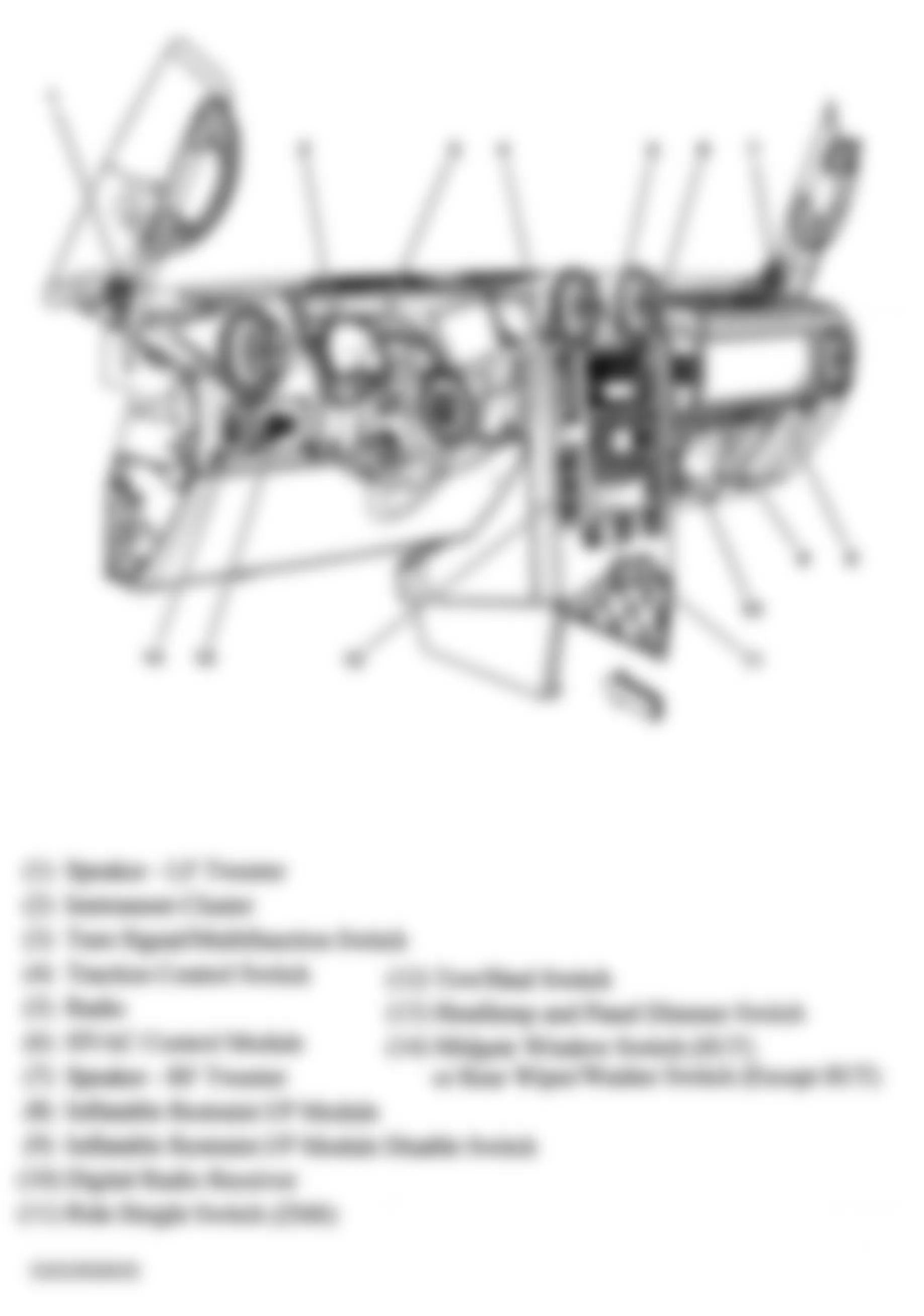
Fig. 102: Hummer H2 2005 - Component Locations - Under Driver's Seat
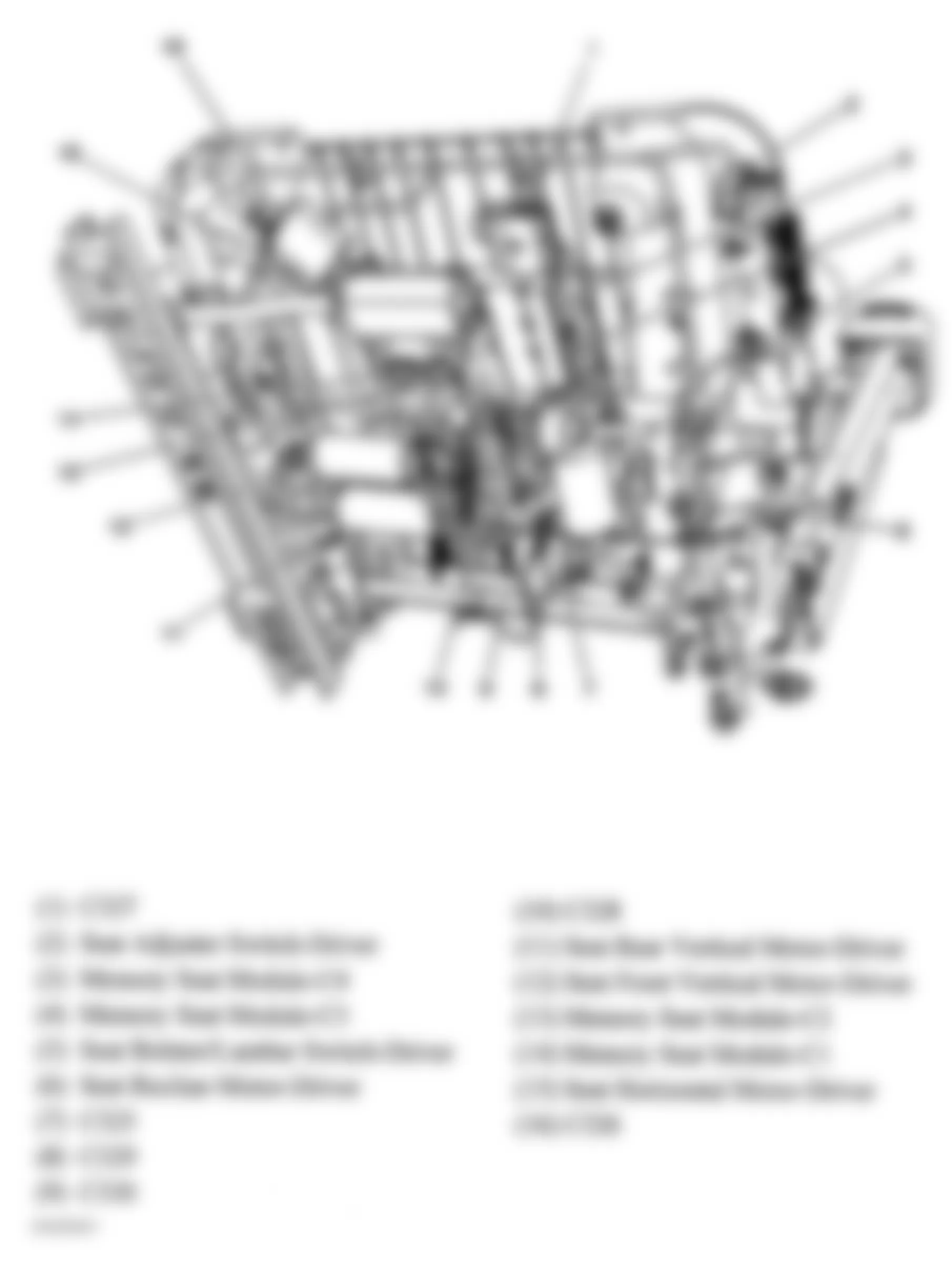
Fig. 103: Hummer H2 2005 - Component Locations - Under Front Passenger's Seat
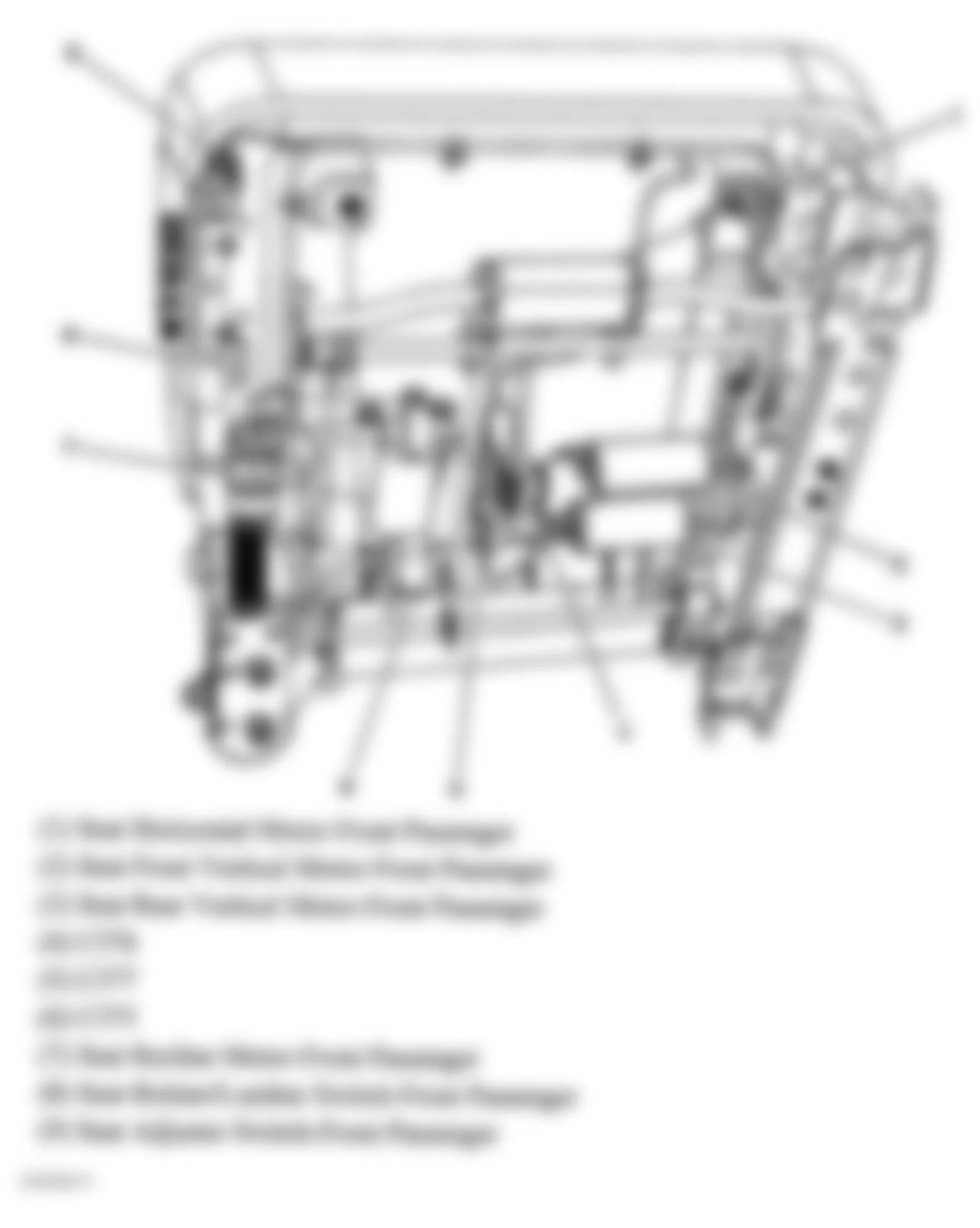
Fig. 104: Hummer H2 2005 - Component Locations - Right Side Of Engine
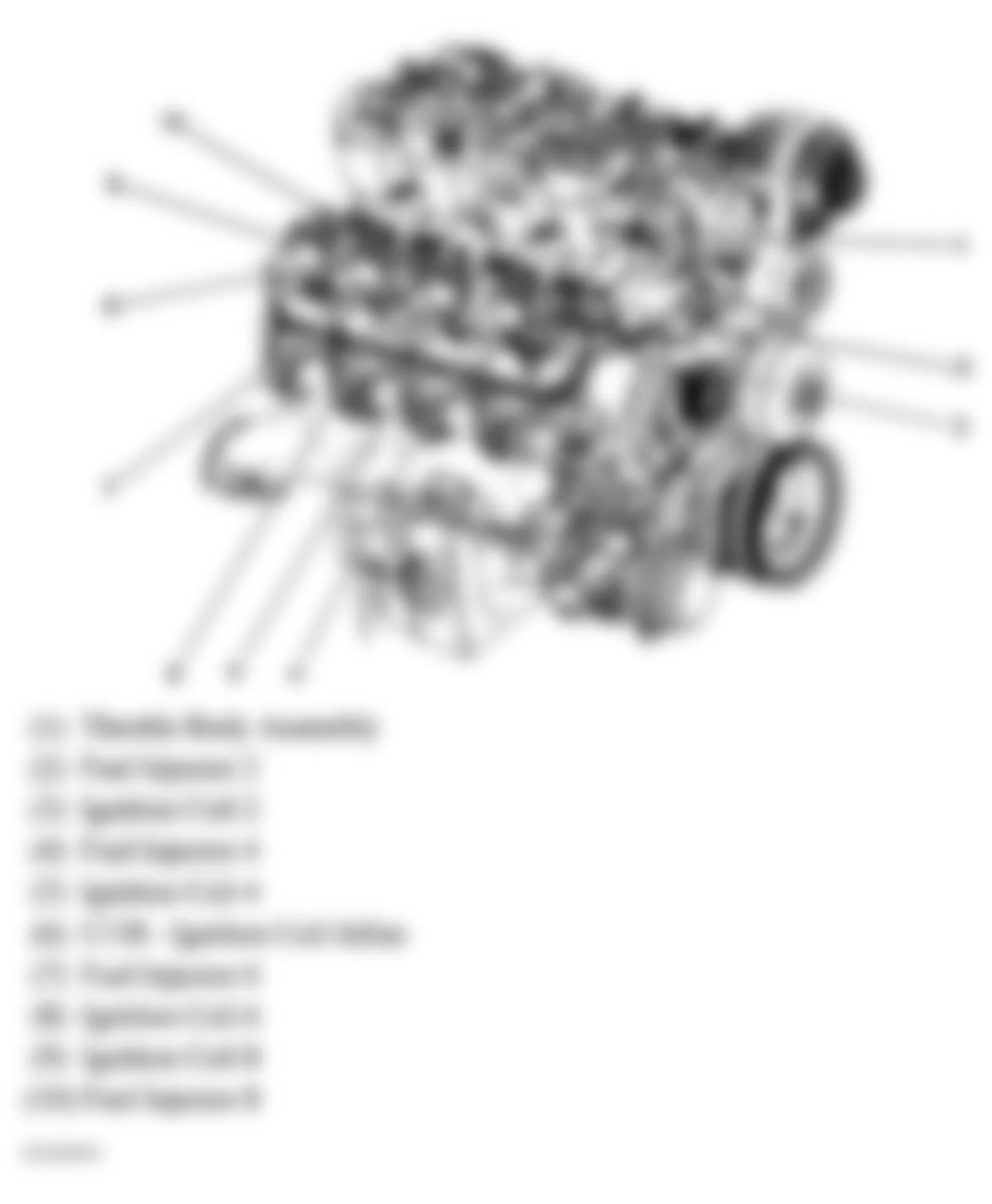
Fig. 105: Hummer H2 2005 - Component Locations - Engine Electrical Components