
 Čeština
 Dansk
Dansk Deutsch
 Ελληνικά
 English
 English
 Español
 Suomi
Suomi Français
 Français
 עברית
עברית Hrvatski
 Magyar
 日本語
日本語 한국어
한국어 Nederlands
 Polski
 Português
 Português
 Română
 Русский
 Slovenčina
 Slovenščina
 Svenska
 Türkçe
 中文 (中国)

Infiniti Q45 1997 - 1997 ELECTRICAL Fuses & Circuit Breakers - Q45
Infiniti Q45 1997 - IDENTIFICATION
WARNING: Vehicle is equipped with air bag supplemental restraint system. Before attempting ANY repairs involving steering column, instrument panel or related components, see SERVICE PRECAUTIONS and DISABLING & ACTIVATING SRS SYSTEM in AIR BAG RESTRAINT SYSTEM article in RESTRAINTS.
WARNING: Always disconnect battery ground cable before servicing high-current fuses. It is recommended that high-current fuses be replaced by a qualified technician.
CAUTION: When battery is disconnected, vehicle computer and memory systems may lose memory data. Driveability problems may exist until computer systems have completed a relearn cycle. See COMPUTER RELEARN PROCEDURES article in GENERAL INFORMATION before disconnecting battery.
Infiniti Q45 1997 - ENGINE COMPARTMENT JUNCTION & RELAY BLOCKS
NOTE: For engine compartment fuse, fusible link and relay box locations, see Fig. 1 .
Infiniti Q45 1997 - Component Locations
- Fusible link box is located at right front of engine compartment. For locations of components, see Fig. 2 . For identification of protected circuits, see Fig. 3 . For wiring diagrams of circuits, see POWER DISTRIBUTION in SYSTEM WIRING DIAGRAMS article.
- Fuse, fusible link, and relay box is located at right front of engine compartment. For locations of components, see Fig. 2 . For identification of protected circuits, see Fig. 3 -Fig. 5 . For wiring diagrams of circuits, see POWER DISTRIBUTION in SYSTEM WIRING DIAGRAMS article.
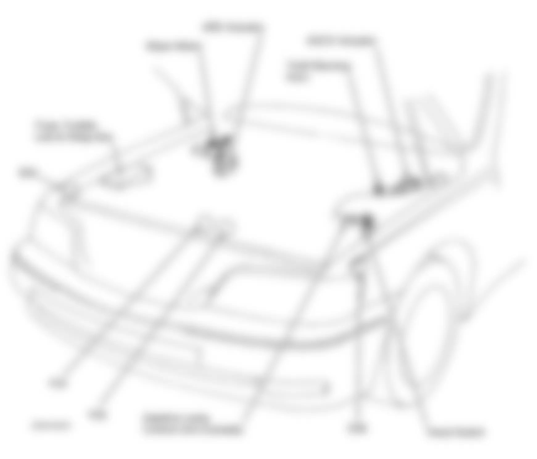

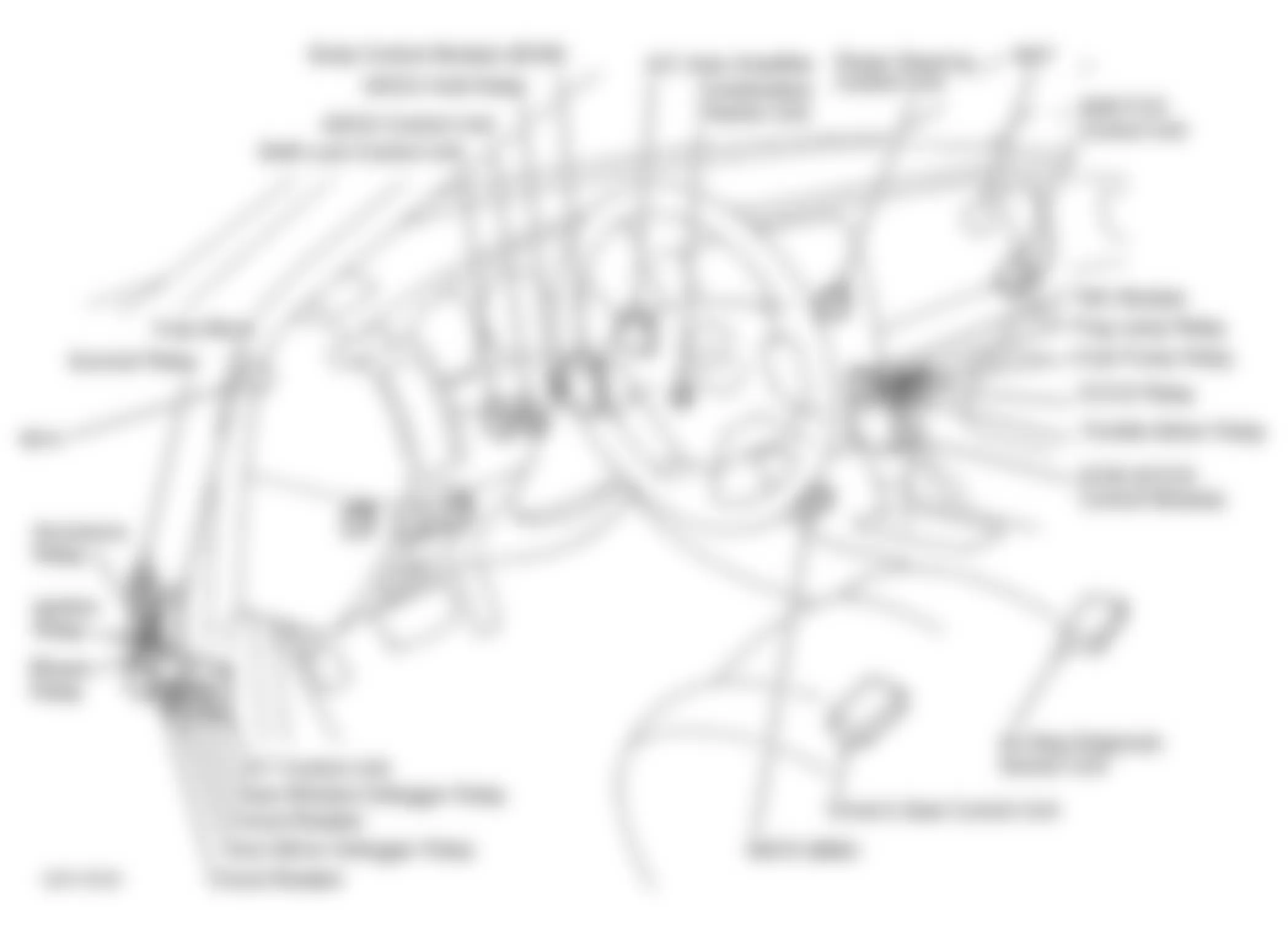
Fig. 2: Infiniti Q45 1997 - Component Locations - Identifying Fuse, Fusible Link & Relay Locations
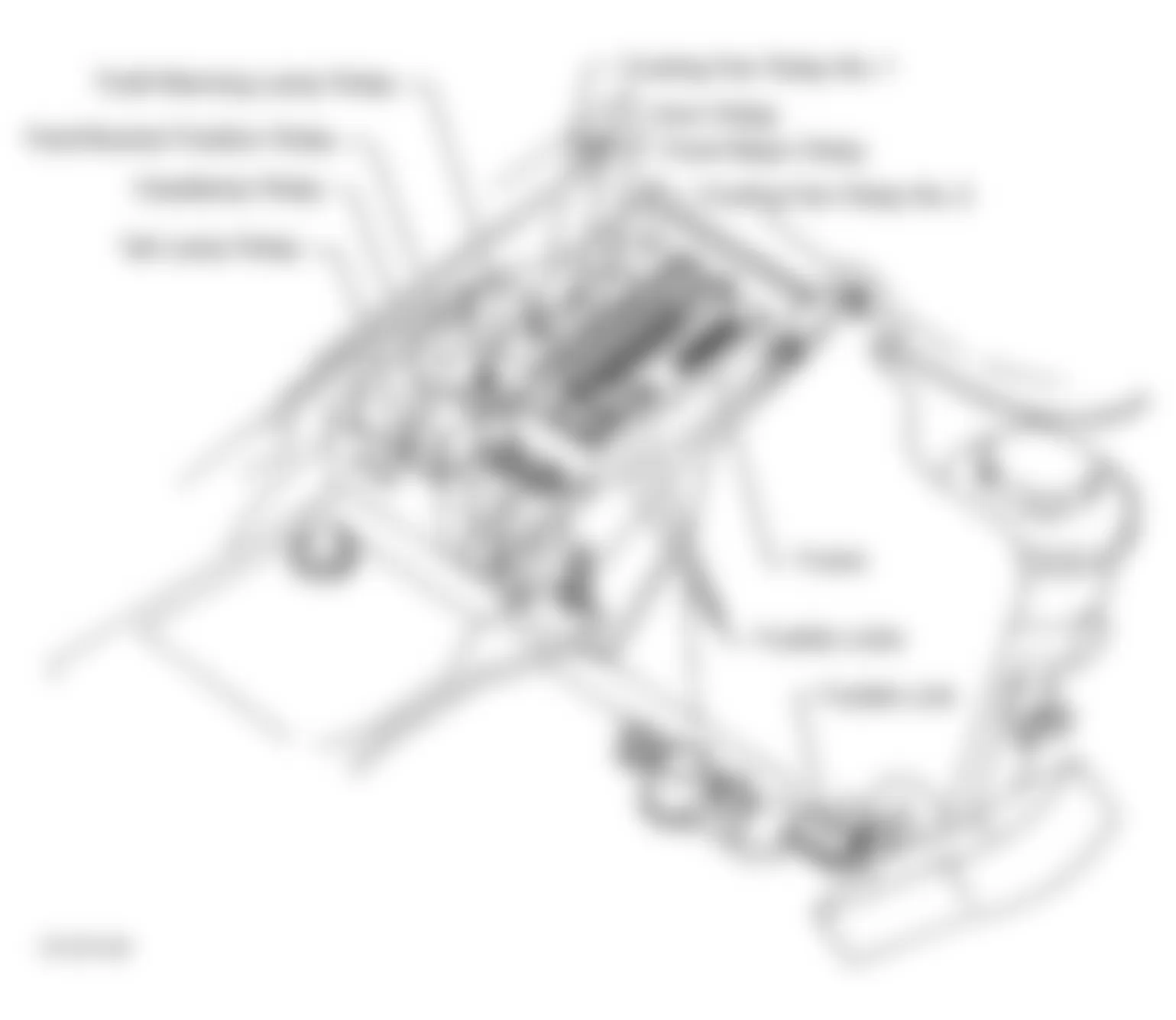
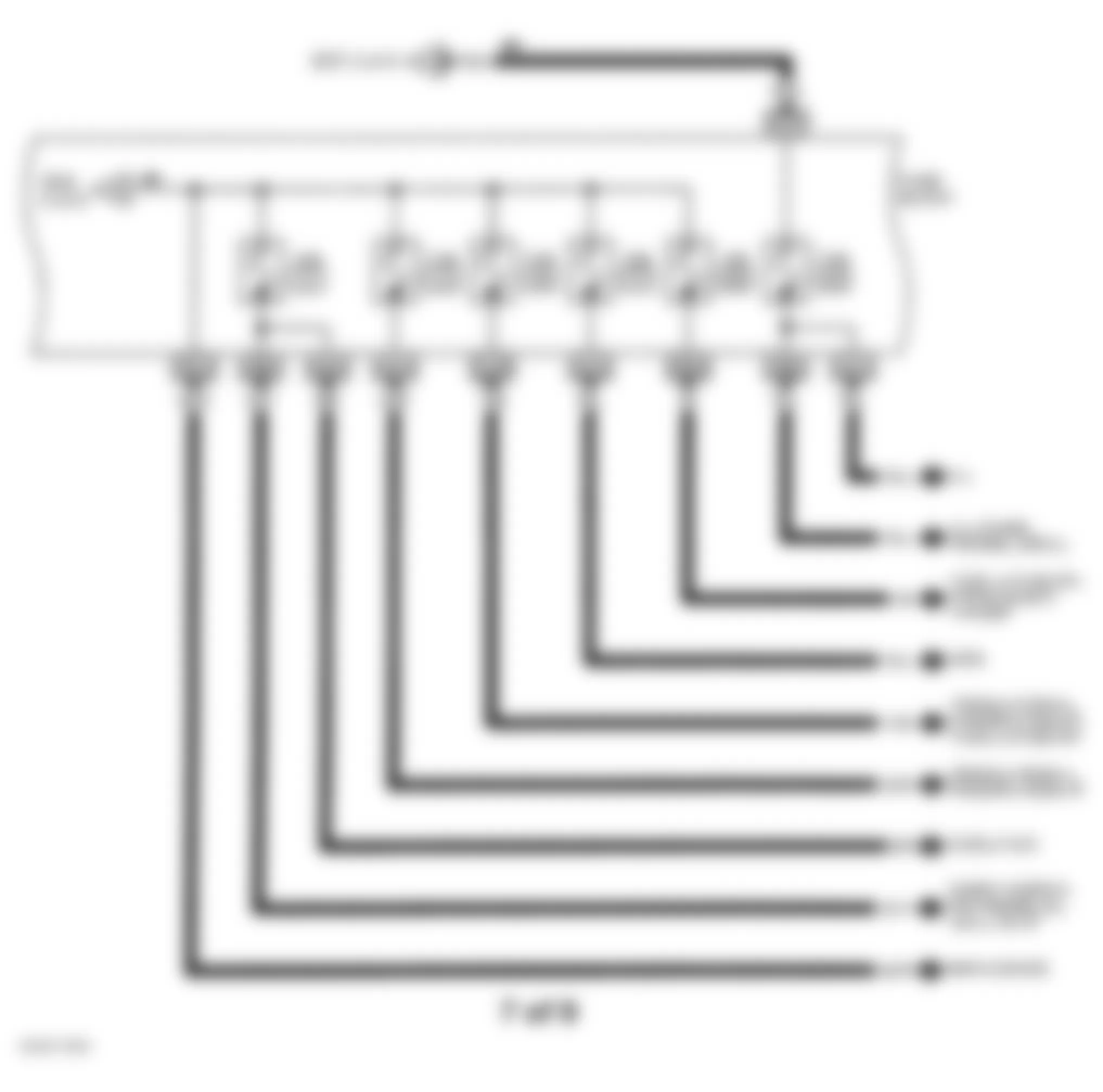
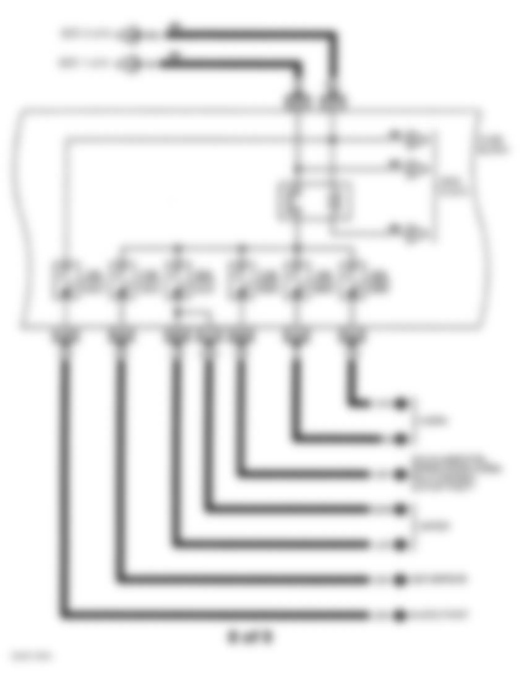
Fig. 3: Infiniti Q45 1997 - Component Locations - Identifying Circuit Protection Components (1 Of 9)
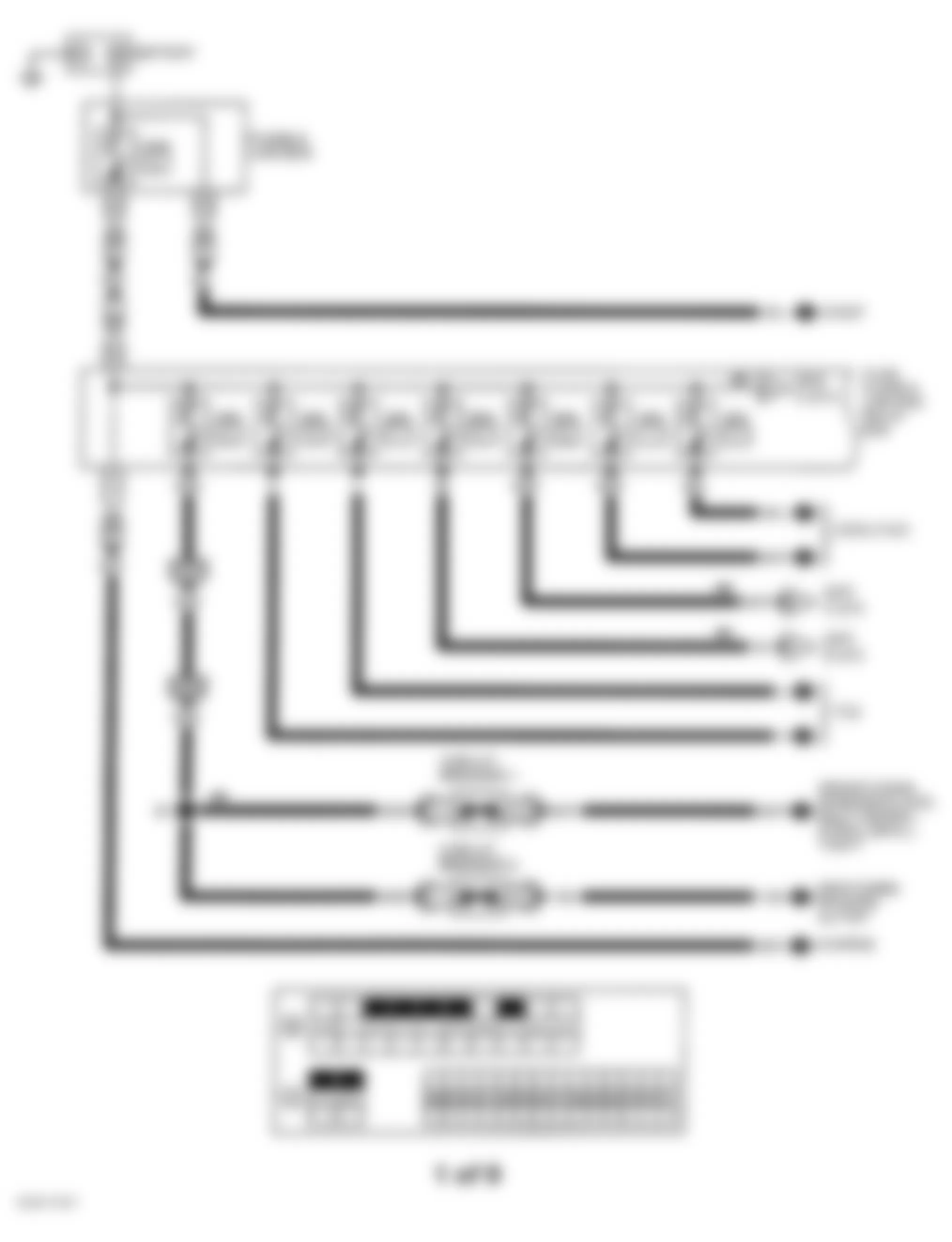
Fig. 4: Infiniti Q45 1997 - Component Locations - Identifying Circuit Protection Components (2 Of 9)
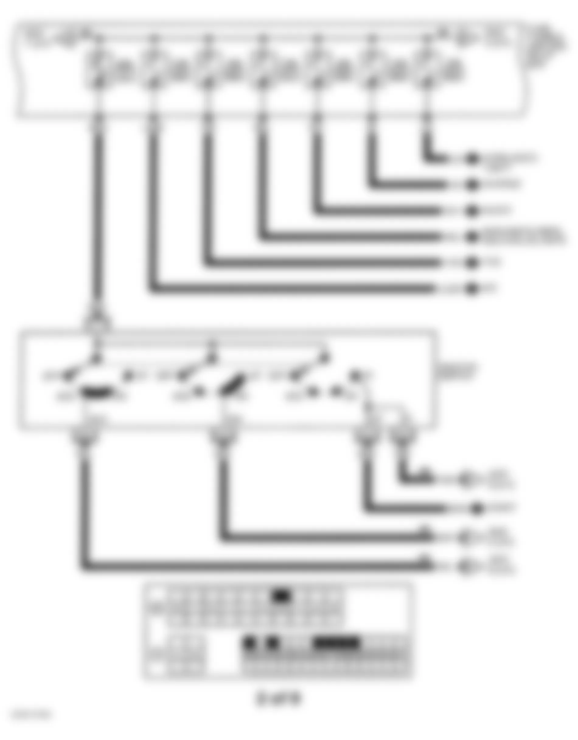
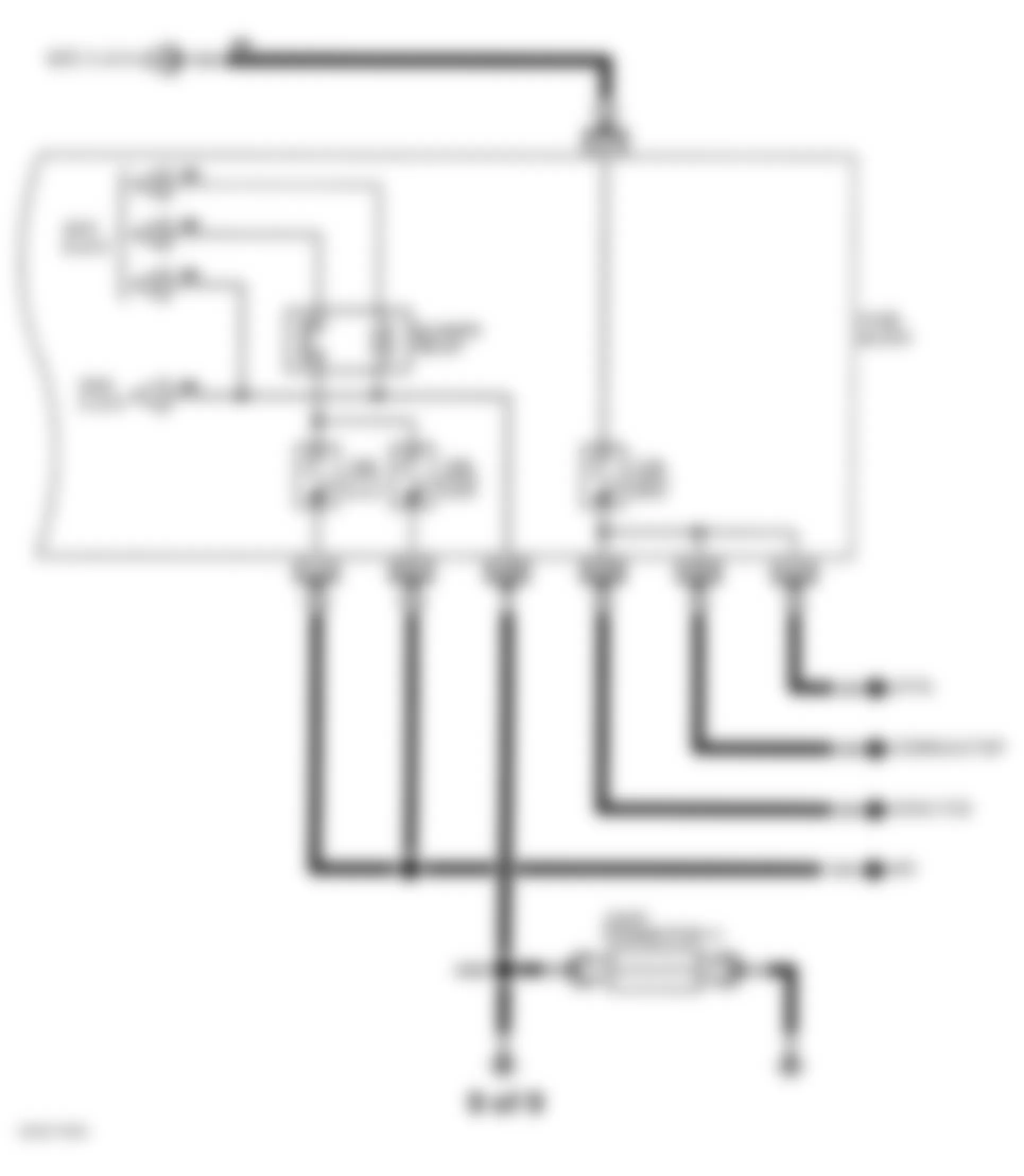
Fig. 5: Infiniti Q45 1997 - Component Locations - Identifying Circuit Protection Components (3 Of 9)
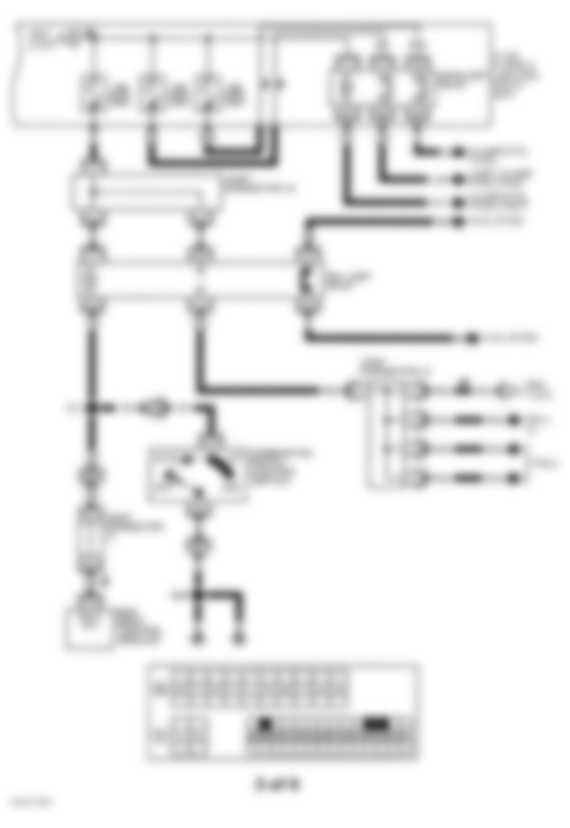
Fig. 6: Infiniti Q45 1997 - Component Locations - Identifying Circuit Protection Components (4 Of 9)
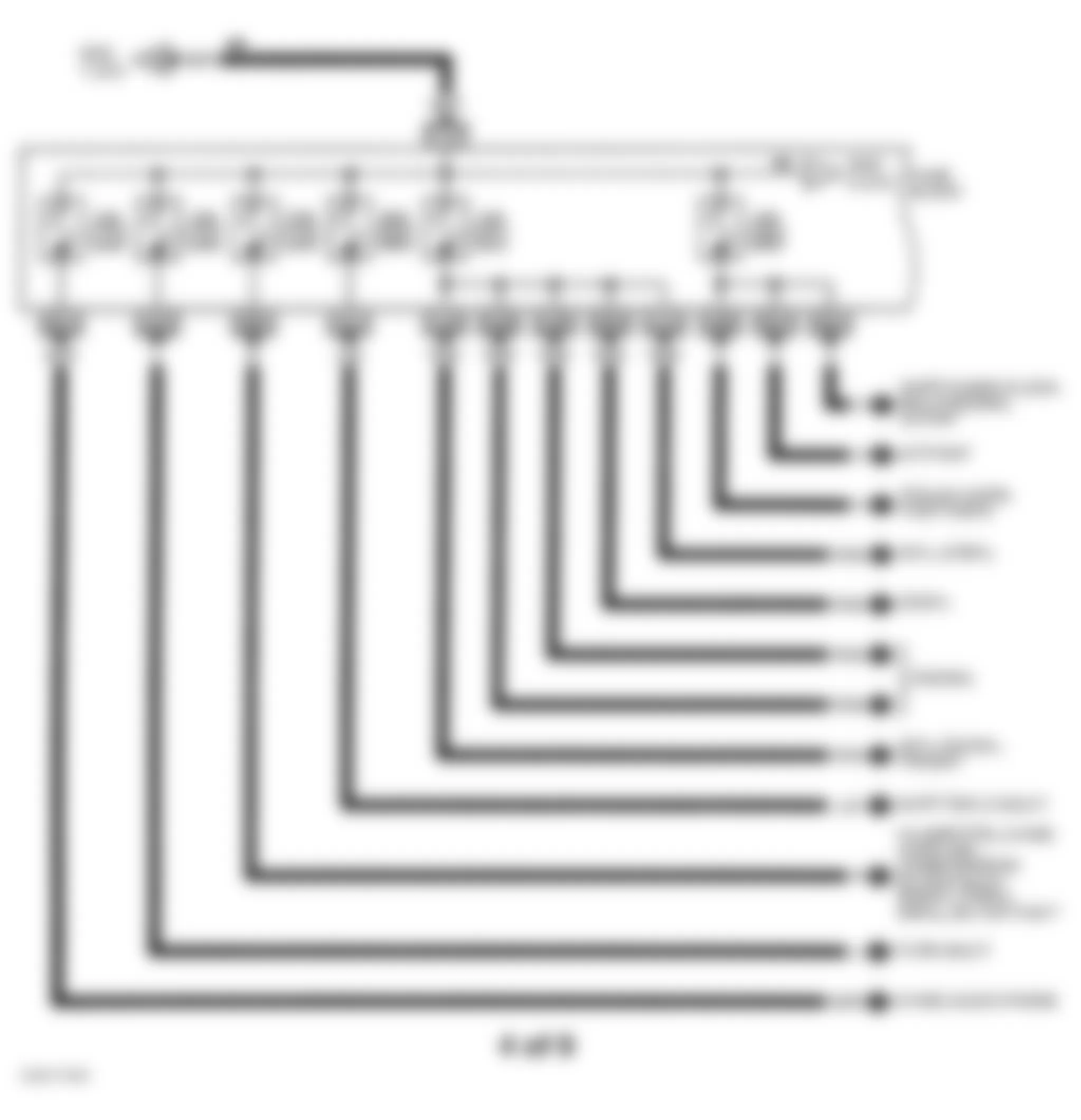
Fig. 7: Infiniti Q45 1997 - Component Locations - Identifying Circuit Protection Components (5 Of 9)
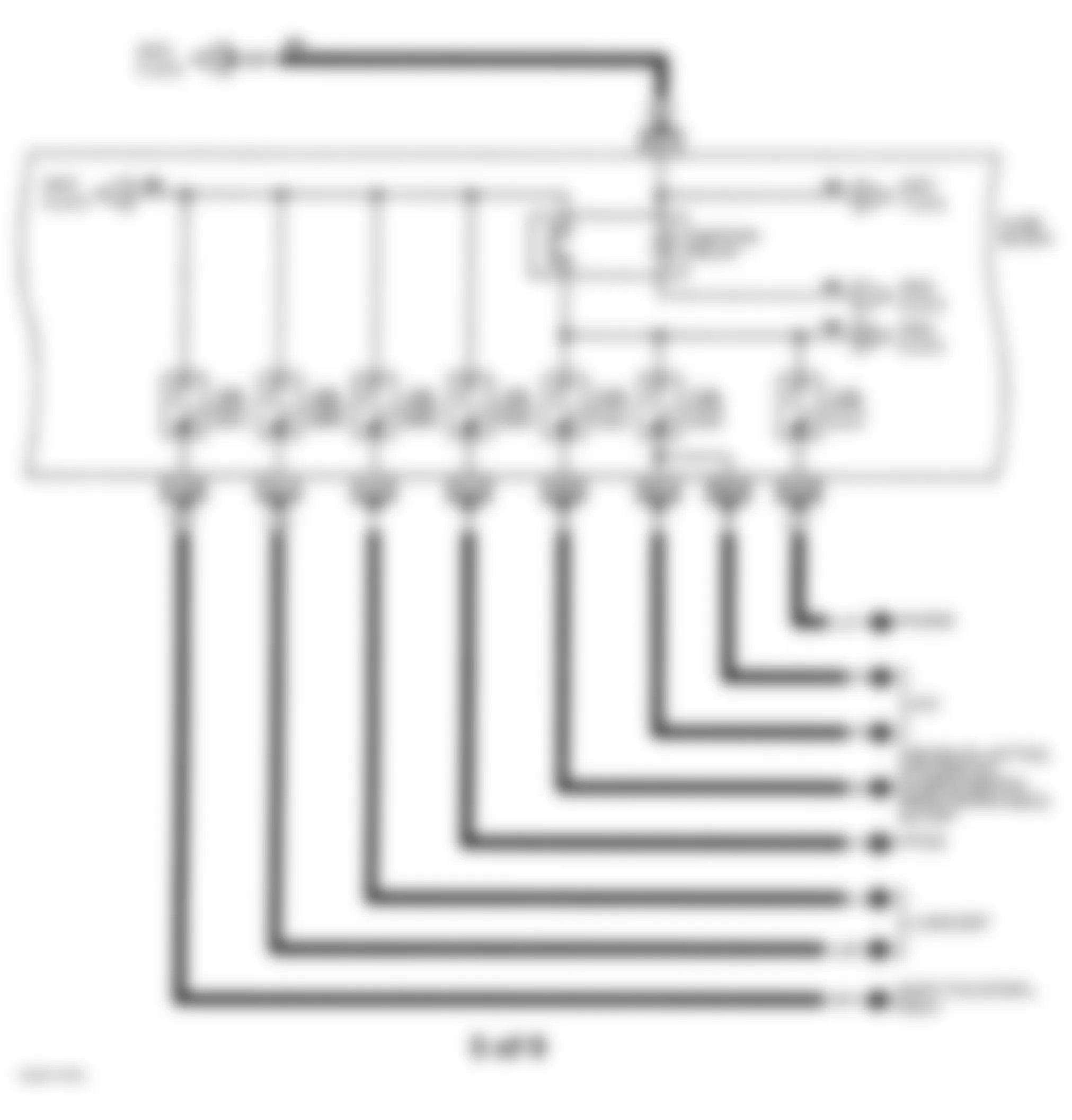
Fig. 8: Infiniti Q45 1997 - Component Locations - Identifying Circuit Protection Components (6 Of 9)
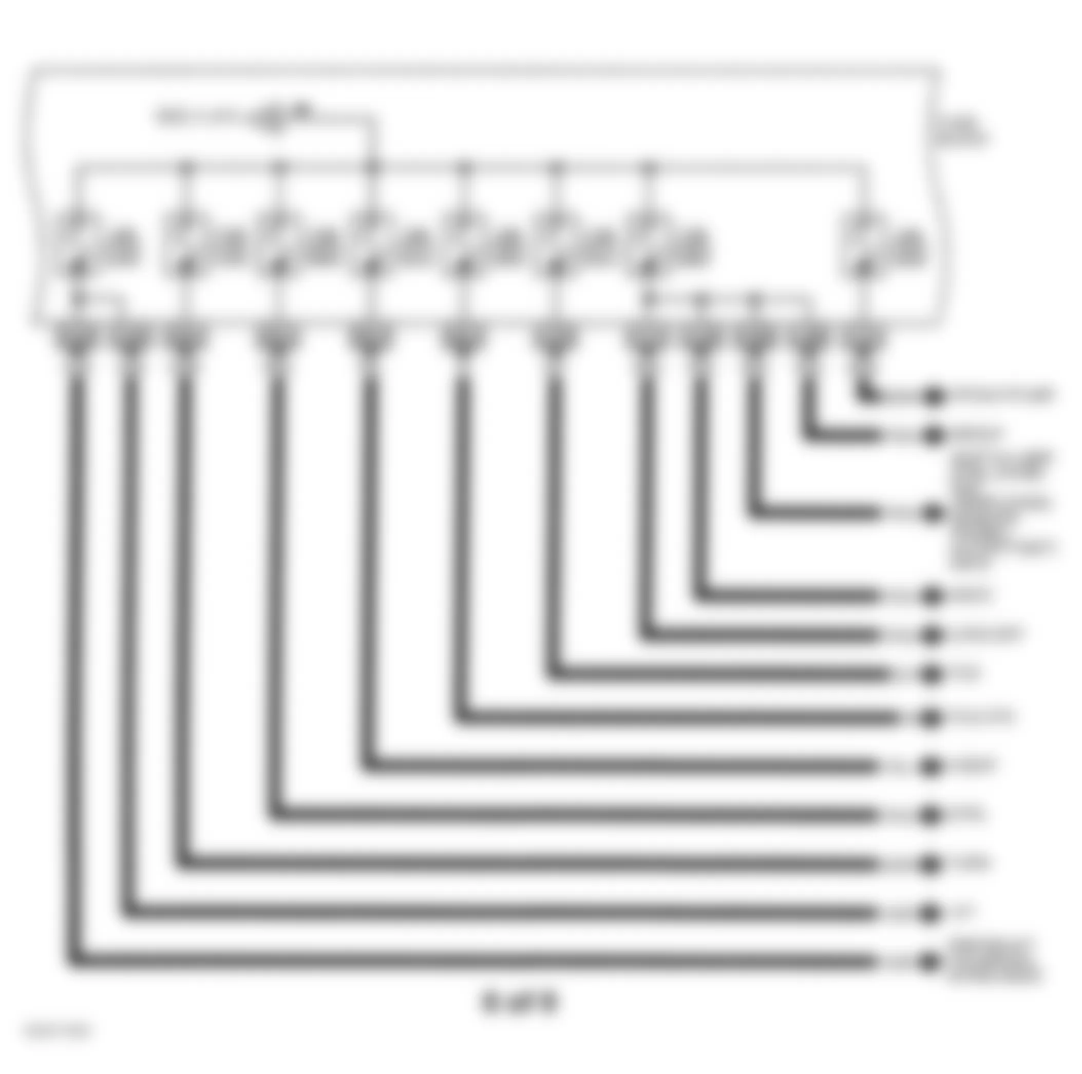
Fig. 9: Infiniti Q45 1997 - Component Locations - Identifying Circuit Protection Components (7 Of 9)
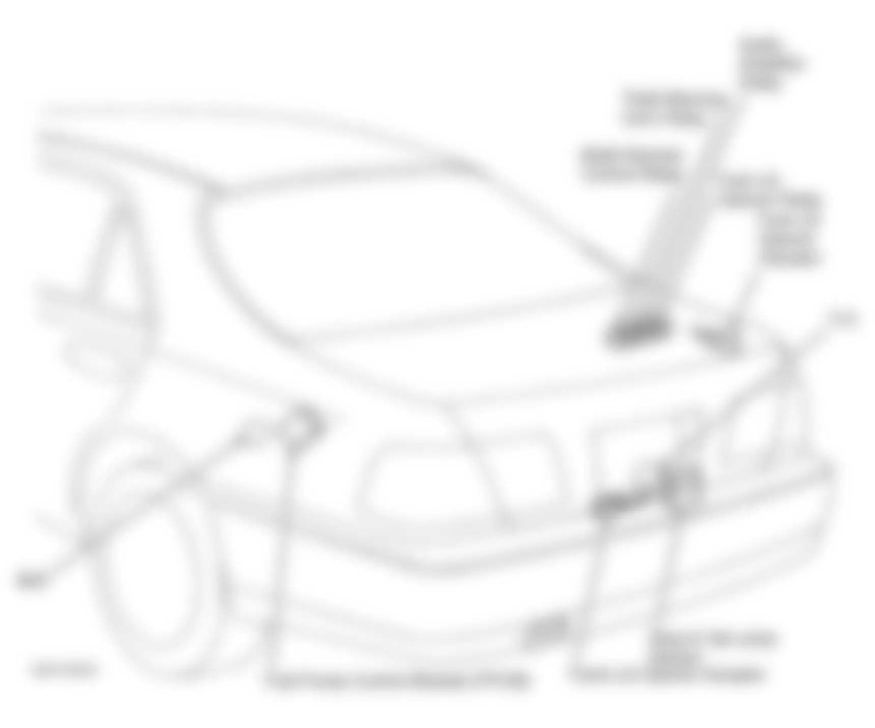
Infiniti Q45 1997 - INSTRUMENT PANEL JUNCTION & RELAY BLOCKS Component Locations
Fuse block is located behind left kick panel. For identification of protected circuits, see Fig. 6 -Fig. 11 . For instrument panel and luggage compartment area fuse block and relay locations, see Fig. 12 and Fig. 13 . For wiring diagram of circuits, see POWER DISTRIBUTION in SYSTEM WIRING DIAGRAMS article.
Infiniti Q45 1997 - CIRCUIT BREAKERS Circuit Breaker Usage
NOTE: For circuit breaker location, see Fig. 12 . For component identification, see Fig. 3 .
Circuit breakers are used in the following:
- Automatic drive positioner In Vehicle Multiplexing System (IVMS) circuit. For wiring diagram, see POWER DISTRIBUTION in SYSTEM WIRING DIAGRAMS article.
- Integrated in front power socket circuit, For wiring diagram, see POWER DISTRIBUTION in SYSTEM WIRING DIAGRAMS article.
- Interior lamp control IVMS circuit. For wiring diagram, see INTERIOR LIGHTS in SYSTEM WIRING DIAGRAMS article.
- Power sun roof circuit. For wiring diagram, see POWER TOP/SUNROOF in SYSTEM WIRING DIAGRAMS article.
- Power window circuit. For wiring diagram, see POWER WINDOWS in SYSTEM WIRING DIAGRAMS article.
- Main power supply, ground and communication circuits of IVMS circuit. For wiring diagram, see POWER DISTRIBUTION in SYSTEM WIRING DIAGRAMS article.
- Power window IVMS circuit. For wiring diagram, see POWER WINDOWS in SYSTEM WIRING DIAGRAMS article.
- Power door lock IVMS circuit circuit. For wiring diagram, see POWER DOOR LOCKS in SYSTEM WIRING DIAGRAMS article.
- Multi-remote control IVMS circuit. For wiring diagram, see POWER DISTRIBUTION in SYSTEM WIRING DIAGRAMS article.
- Step Lamp IVMS circuit. For wiring diagram, see INTERIOR LIGHTS in SYSTEM WIRING DIAGRAMS article.
- Illumination IVMS circuit. For wiring diagram, see INTERIOR LIGHTS in SYSTEM WIRING DIAGRAMS article.
- Theft warning system IVMS circuit. For wiring diagram, see ANTI-THEFT in SYSTEM WIRING DIAGRAMS article.