AIR CONDITIONING
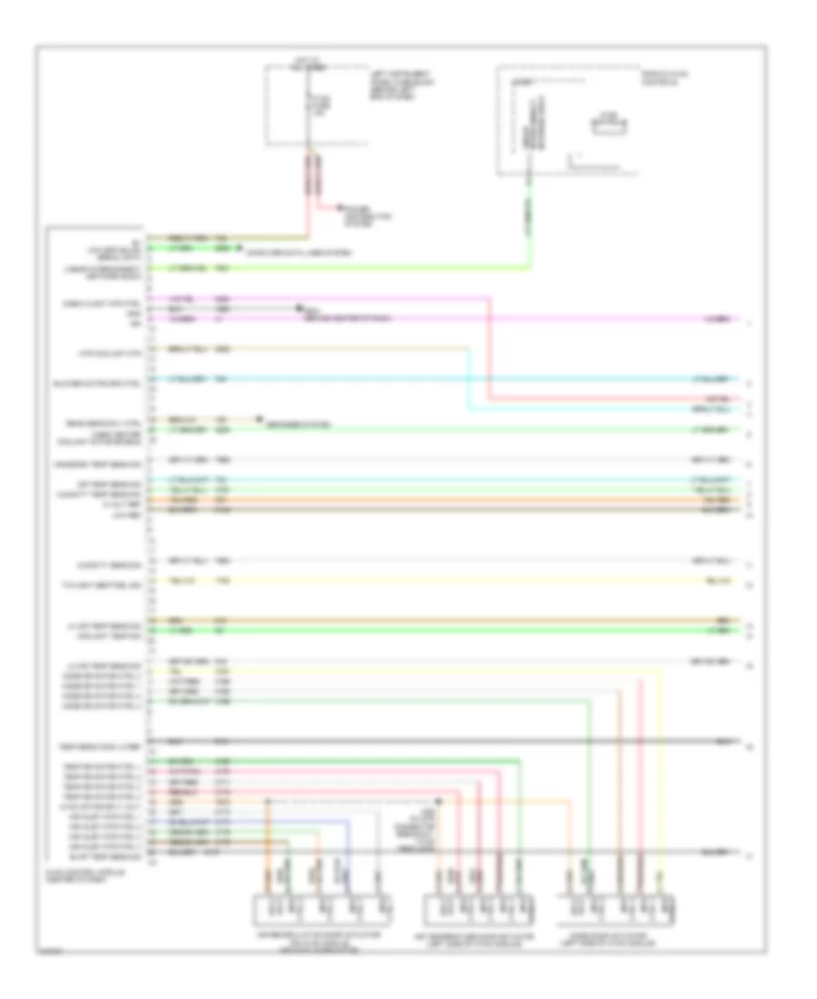
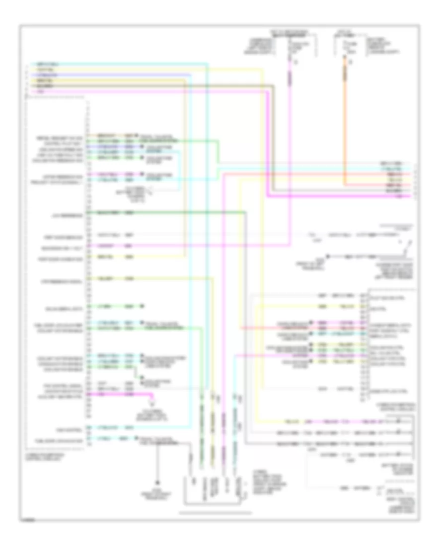
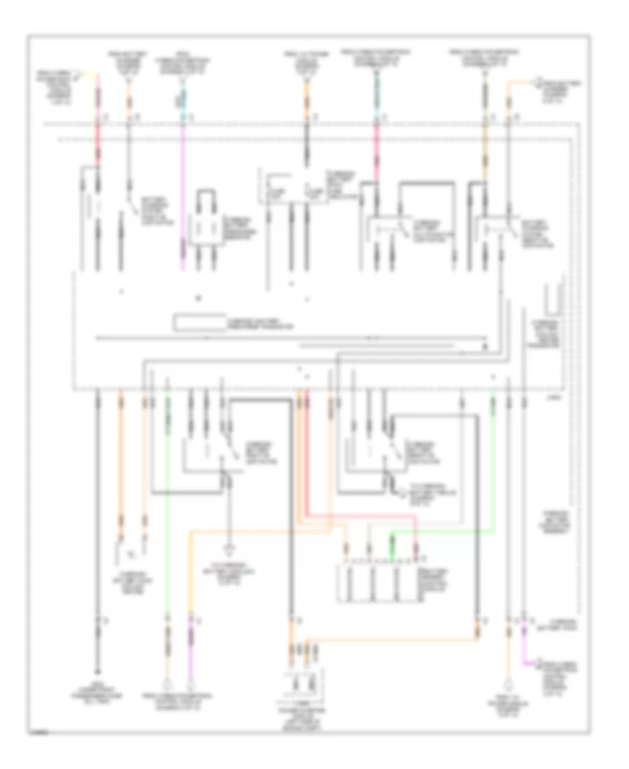
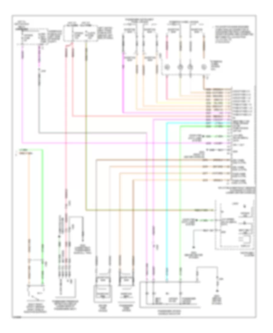
Automatic A/C Wiring Diagram (1 of 4) for Chevrolet Volt 2011
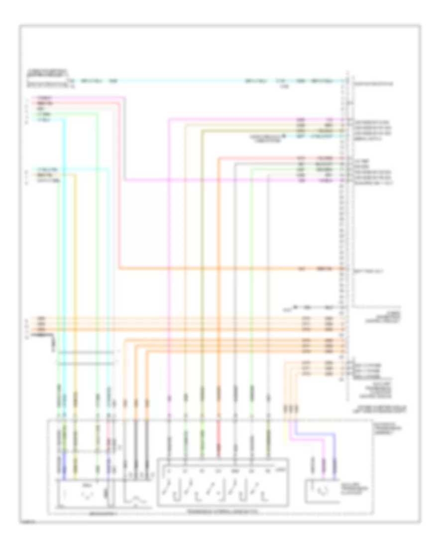
List of elements for Automatic A/C Wiring Diagram (1 of 4) for Chevrolet Volt 2011:
- 5 volt ref
- Air inlet mtr ctrl 1
- Air inlet mtr ctrl 2
- Air inlet mtr ctrl 3
- Air inlet mtr ctrl 4
- Air recirculation door actuator (on hvac module, above blower motor)
- Air temp sens sig
- Air temperature door actuator (left side of hvac module)
- B+ low spd gmlan serial data
- Blower motor spd ctrl
- Cabin clant mtr ctrl
- Cabin heater coolant motor enable
- Computer data lines system
- Coolant temp sig
- Ctrl 1 mtr
- Ctrl 2 mtr
- Ctrl 4 mtr
- Defogger system
- Evap temp sens sig
- G204 (behind center of dash)
- Gnd
- Hot at all times
- Htr coolant mtr
- Humidity sens sig
- Humidity temp sens sig
- Hvac control module (center of dash)
- Hvac controls
- Hvac fuse 10a
- Hvac motor sply volt
- Ign
- Interconnect network bus 9
- J225 (in x275 connector breakout, 7.5 cm from x275)
- Left instrument panel fuse block (behind left end of dash)
- Lh air temp sens sig
- Linear
- Linear interconnect network bus 9
- Logic
- Low ref
- Mode door actuator (left side of hvac module)
- Mode dr motor ctrl 1
- Mode dr motor ctrl 2
- Mode dr motor ctrl 3
- Mode dr motor ctrl 4
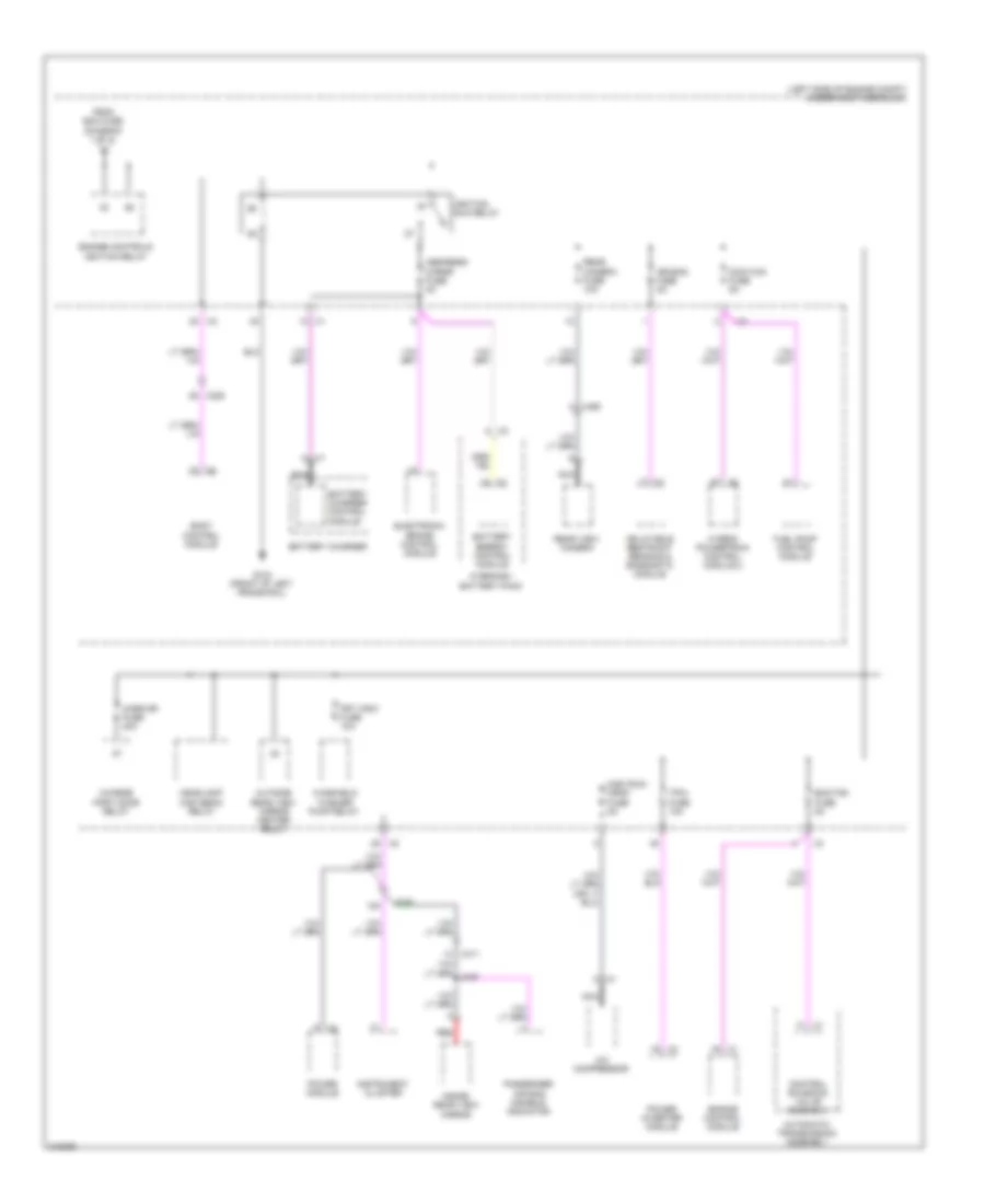
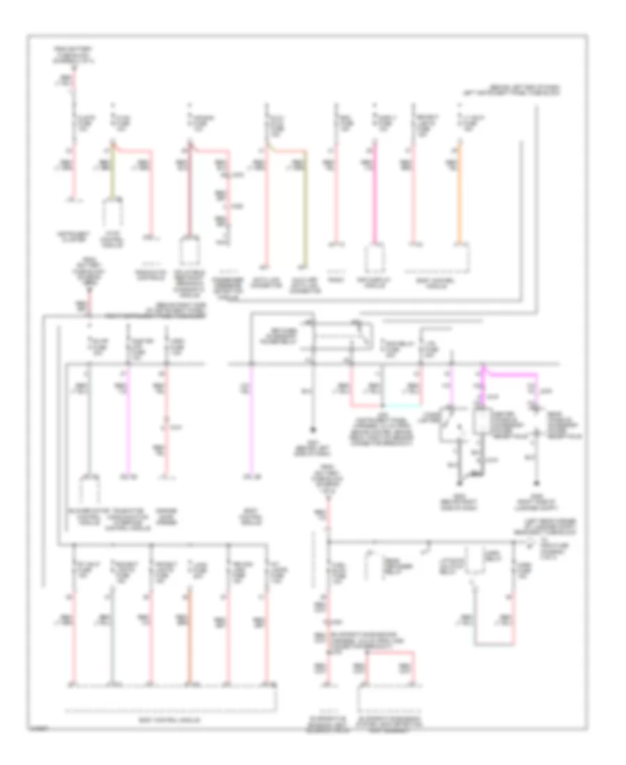
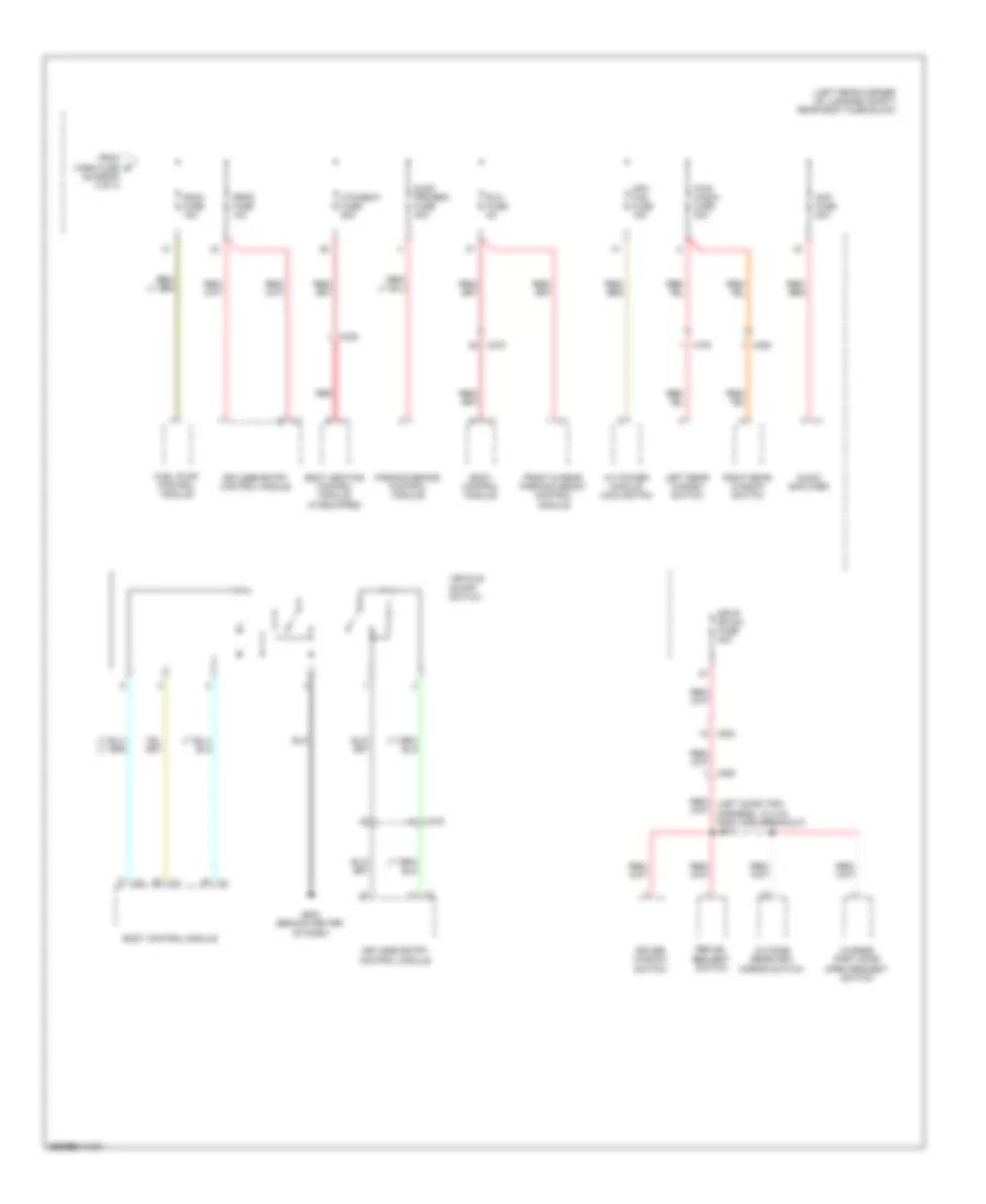
- Power distribution system
- Radio & hvac controls
- Rear defog rly ctrl
- Temp dr motor ctrl 1
- Temp dr motor ctrl 2
- Temp dr motor ctrl 3
- Temp dr motor ctrl 4
- Temp sens comm lo ref
- Twilight sentinel sig
- Volt sply
- Windscrn temp sens sig
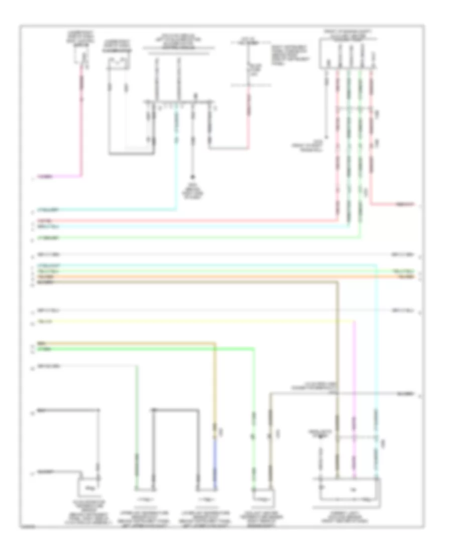
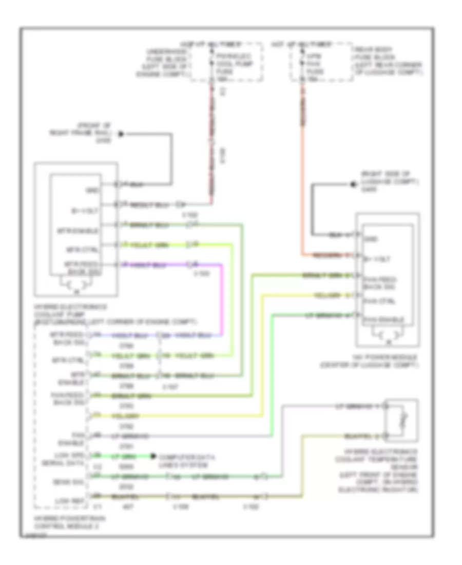
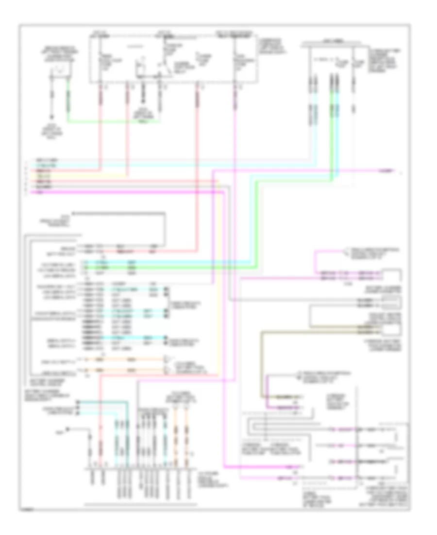
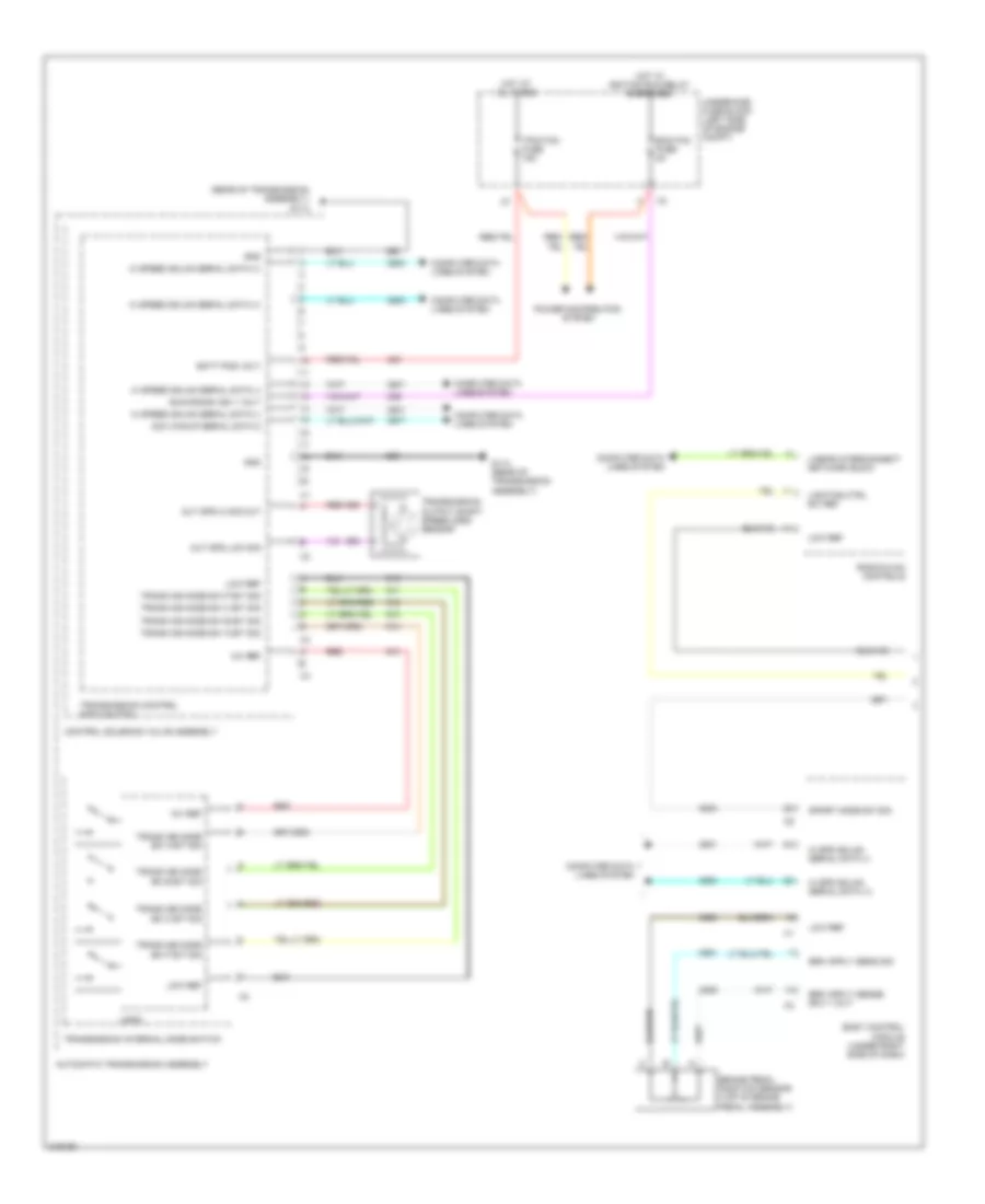
Automatic A/C Wiring Diagram (2 of 4) for Chevrolet Volt 2011
List of elements for Automatic A/C Wiring Diagram (2 of 4) for Chevrolet Volt 2011:
- (10 cm from x260 connector breakout) j220
- (front of engine compt) auxiliary heater coolant pump
- (on hvac module, left of blower motor) blower motor control module
- (under right side of dash)
- (under right side of dash) body control module
- A/c evaporator temperature sensor (behind instrument panel, right side of hvac module assembly)
- Ambient light/ sunload sensor (front center of dash)
- B+ volt
- Blower motor
- Blower mtr fan ctrl
- Blower mtr spd ctrl
- Blwr fuse 30a
- Coolant heater temperature sensor (right rear of engine compt)
- F5dr
- Fdback sig
- G102 (front of right frame rail)
- G202 (behind right side of dash)
- Gnd
- Headlights system
- Hot at all times
- J150
- Lower air temperature sensor duct (behind instrument panel, left lower hvac duct)
- Motor ctrl
- Mtr anable
- Right instrument panel fuse block (behind right side of instrument panel)
- Upper air temperature sensor duct (behind instrument panel, left upper hvac duct)
- X105
- X180
- X250
- X252
- X275
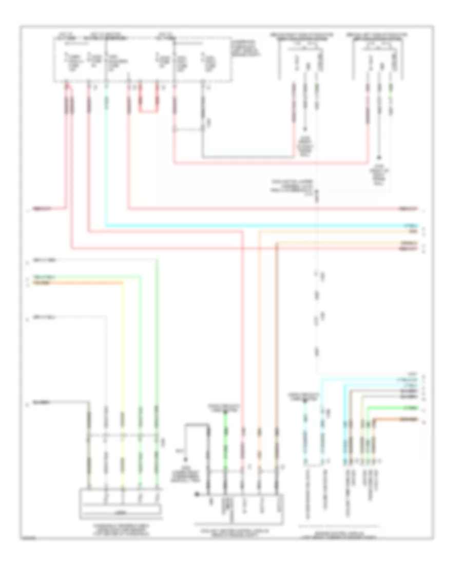
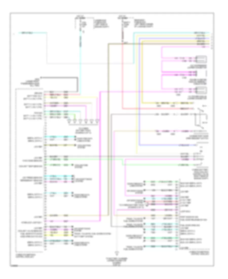
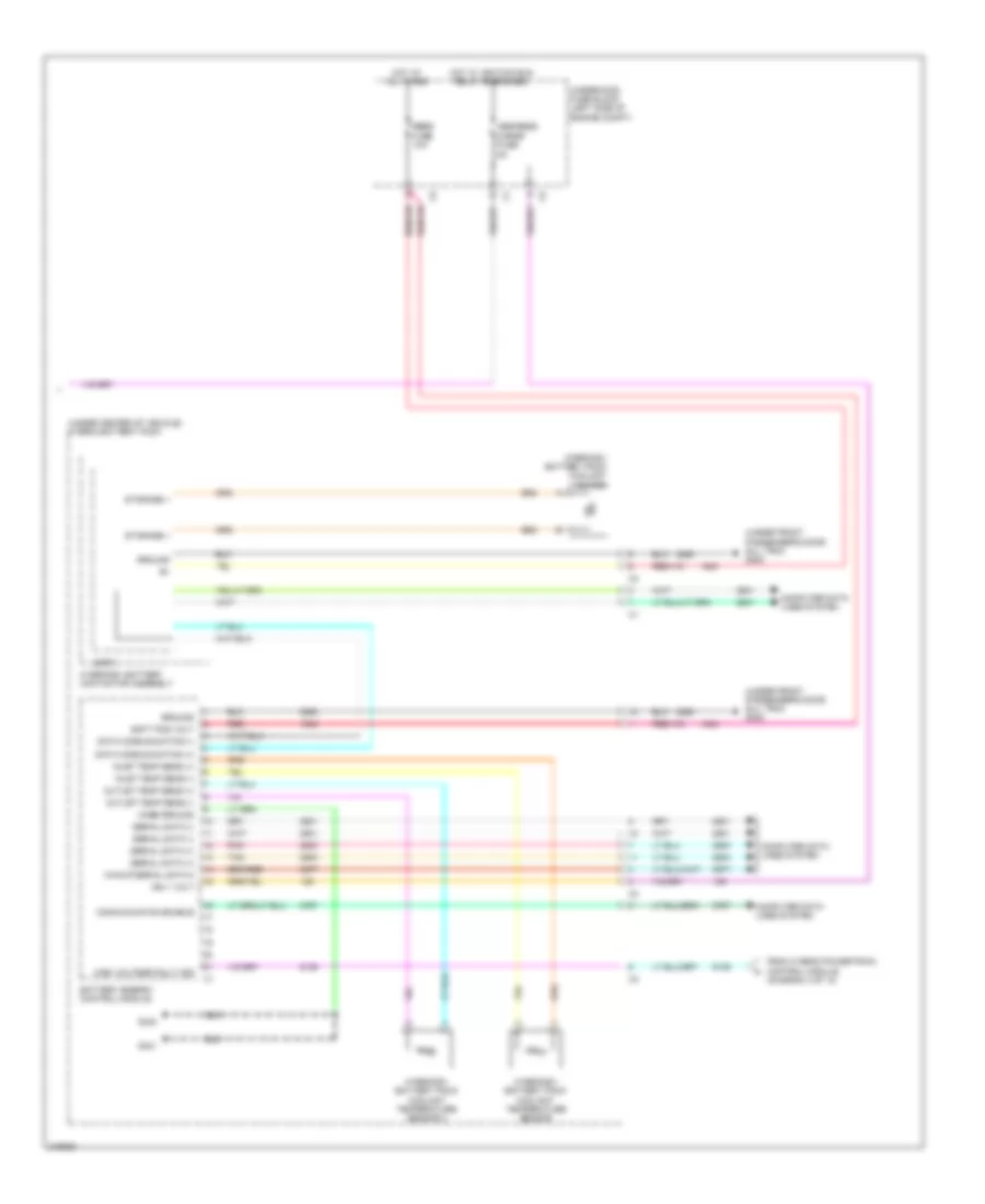
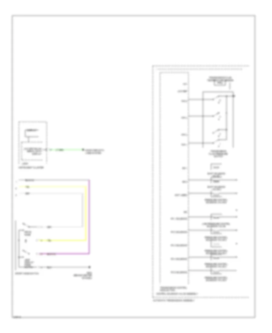
Automatic A/C Wiring Diagram (3 of 4) for Chevrolet Volt 2011
List of elements for Automatic A/C Wiring Diagram (3 of 4) for Chevrolet Volt 2011:
- (behind left side of radiator) left cooling fan motor
- (behind right side of radiator) right cooling fan motor
- (cooling fan jumper harness, 4.5 cm from x103 breakout) j110
- 5 volt ref
- Access wakup srl data
- Accm fuse 5a
- B+ volt
- Batt (+)
- Batt (-)
- Cabin pmp/vlv fuse 15a
- Chcm fuse 5a
- Computer data lines system
- Cool fan 1 fuse 30a
- Cool fan 2 fuse 30a
- Coolant heater control module (rear of engine compt)
- Coolant temp sens sig
- Cooling fan spd sig
- Ctrl sig
- Engine control module (left front corner of engine compt)
- G105 (front of right frame rail)
- G302 (under front passenger's door sill trim)
- Gnd
- Hot at all times
- Hot w/ ignition run relay energized
- Logic
- Low ref
- Misc run/crnk fuse 5a
- Nca
- Press sens sig
- Red
- Serial data gmlan low spd
- Underhood fuse block (left side of engine compt)
- Windshield temperature & inside moisture sensor (top center of windshield)
- X103
- X104
- X107
- X190
- X310
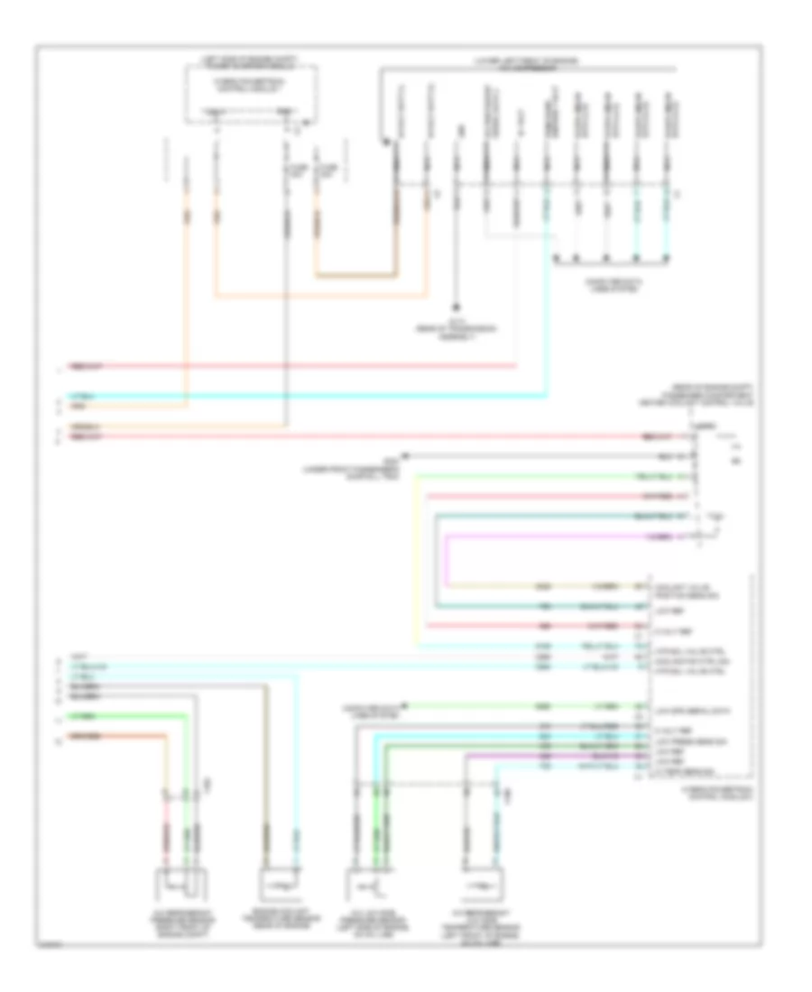
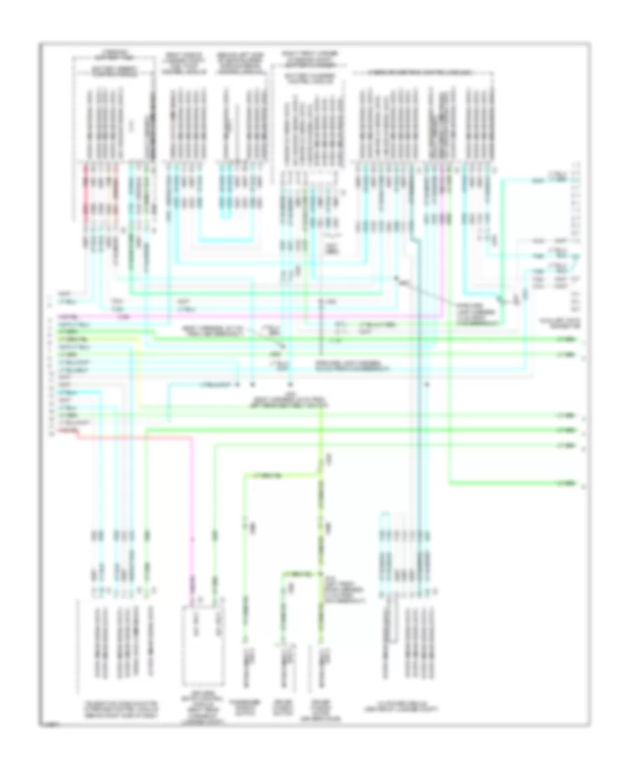
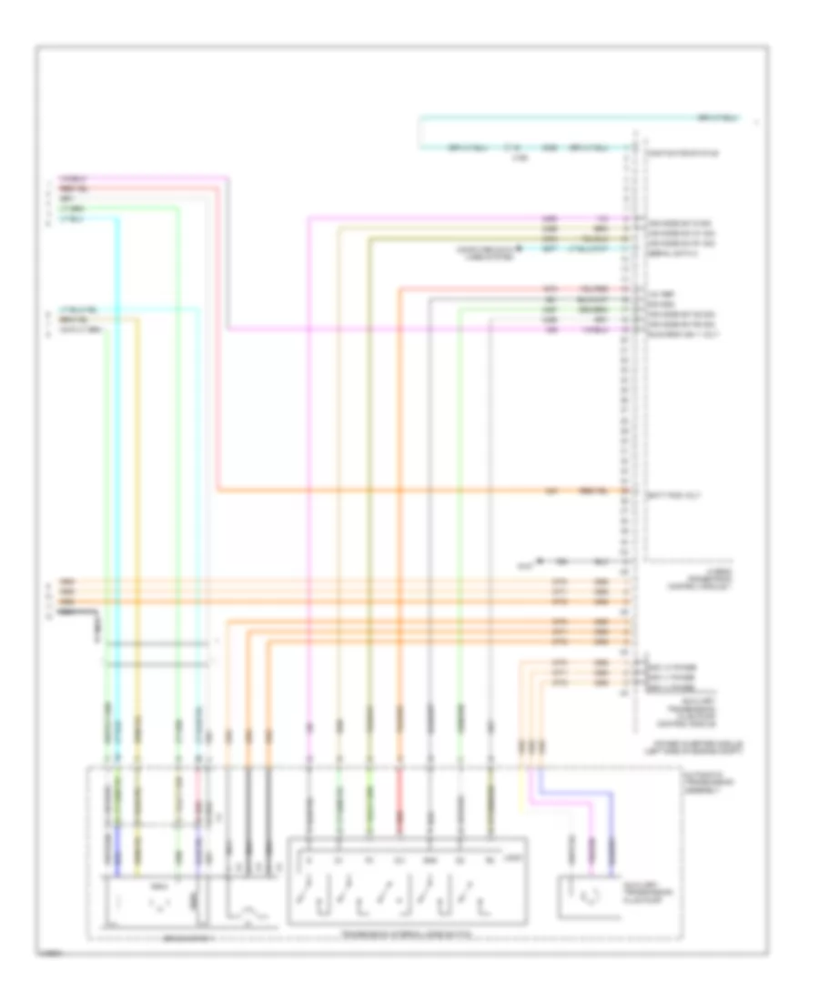
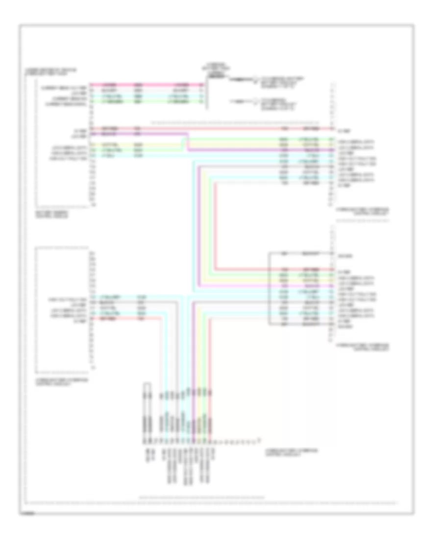
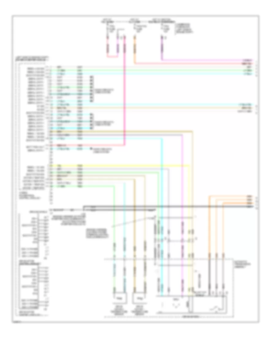
Automatic A/C Wiring Diagram (4 of 4) for Chevrolet Volt 2011
List of elements for Automatic A/C Wiring Diagram (4 of 4) for Chevrolet Volt 2011:
- (left side of engine compt) power inverter module
- (lower left front of engine) a/c compressor
- (rear of engine compt) passenger compartment heater coolant control valve
- 300v+
- 300v-
- 5 volt ref
- A/c low side pressure sensor (left side of engine, on a/c line)
- A/c refrigerant low side temperature sensor (left front of engine, on a/c line)
- A/c refrigerant pressure sensor (right front of engine compt)
- Access wakup serial data 2
- B+ volt
- Computer data lines system
- Coolant valve position sens sig
- Cooling fan ctrl sig
- Data (+) (1) hi spd gmlan
- Data (-) (1) hi spd gmlan
- Engine coolant temperature sensor (rear of engine)
- Fuse 30a
- G113 (rear of transmission assembly)
- G302 (under front passenger's door sill trim)
- Gnd
- Hi spd gmlan data (-) (1)
- Hi temp sens sig
- Hi volt batt (+)
- Hi volt batt (-)
- Htr sol valve ctrl
- Hybrid powertrain control module 1
- Hybrid powertrain control module 2
- Logic
- Low press sens sig
- Low ref
- Low spd serial data
- Nca
- Run/crank ignition 1 volt
- X102
- X190
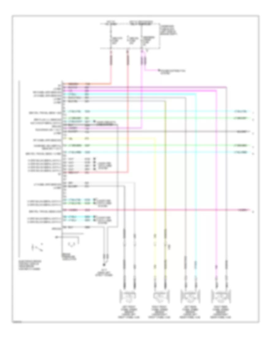
ANTI-LOCK BRAKES
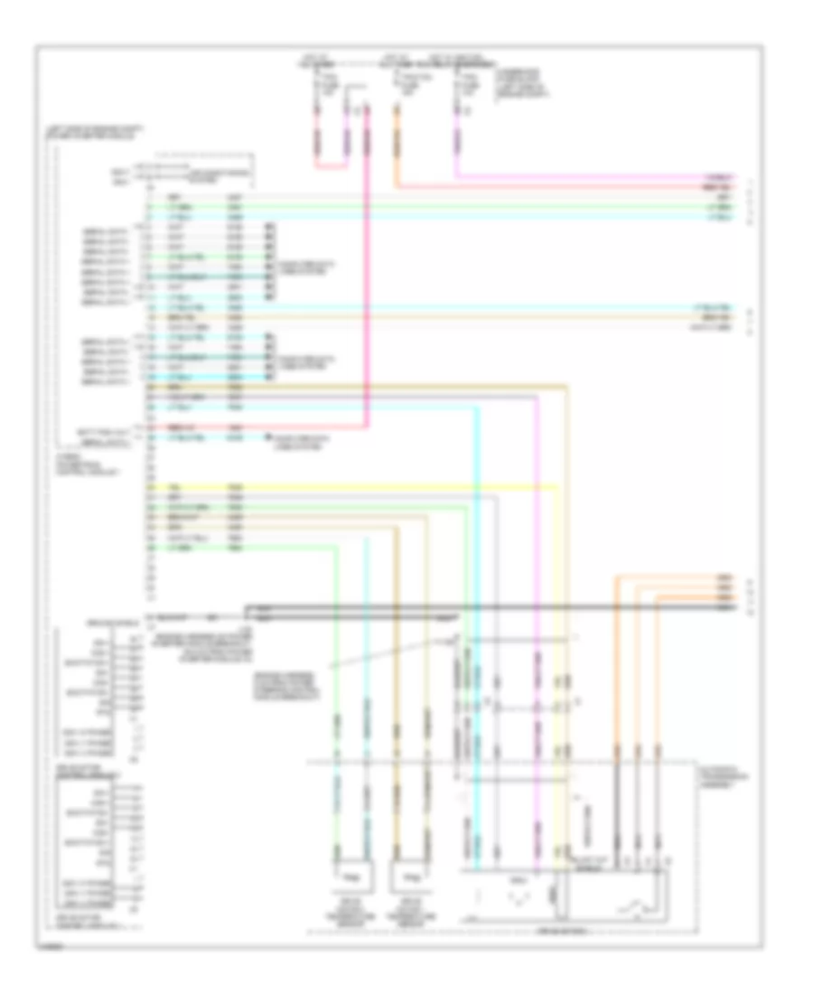
Anti-lock Brakes Wiring Diagram (1 of 2) for Chevrolet Volt 2011
List of elements for Anti-lock Brakes Wiring Diagram (1 of 2) for Chevrolet Volt 2011:
- Abs mdl fuse 40a
- Abs mtr fuse 60a
- Abs/ress/ chrgr fuse 5a
- Acc wakup serial data 2
- Brake pressure modulator
- Brk fluid lvl sens sig
- Brk pdl travel sens 1 hi ref
- Brk pdl travel sens 1 sig
- Brk pdl travel sens 2 sig
- Combined veh inertial sens sply volt
- Computer data lines system
- Electronic brake control module (near brake master cylinder)
- G117 (near left strut tower)
- Ground
- Hi spd gmlan serial data (+)
- Hi spd gmlan serial data (-)
- Hot at all times
- Hot w/ ignition run relay energized
- Left front wheel speed sensor (inside left front wheel hub)
- Left rear wheel speed sensor (inside left rear wheel hub)
- Lf wheel spd sens sig
- Lo ref
- Lr wheel spd sens sig
- Nca
- Power distribution system
- Rf wheel spd sens sig
- Right front wheel speed sensor (inside right front wheel hub)
- Right rear wheel speed sensor (inside right rear wheel hub)
- Rr wheel spd sens sig
- Run/crank ign 1 volt
- Underhood fuse block (left side of engine compt)
- X105
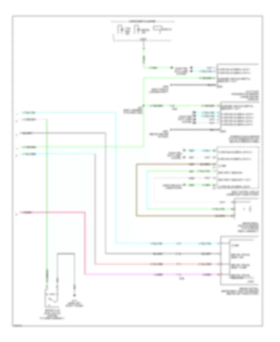
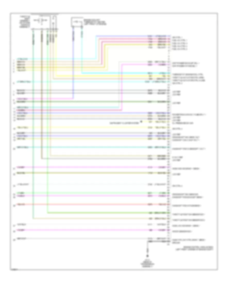
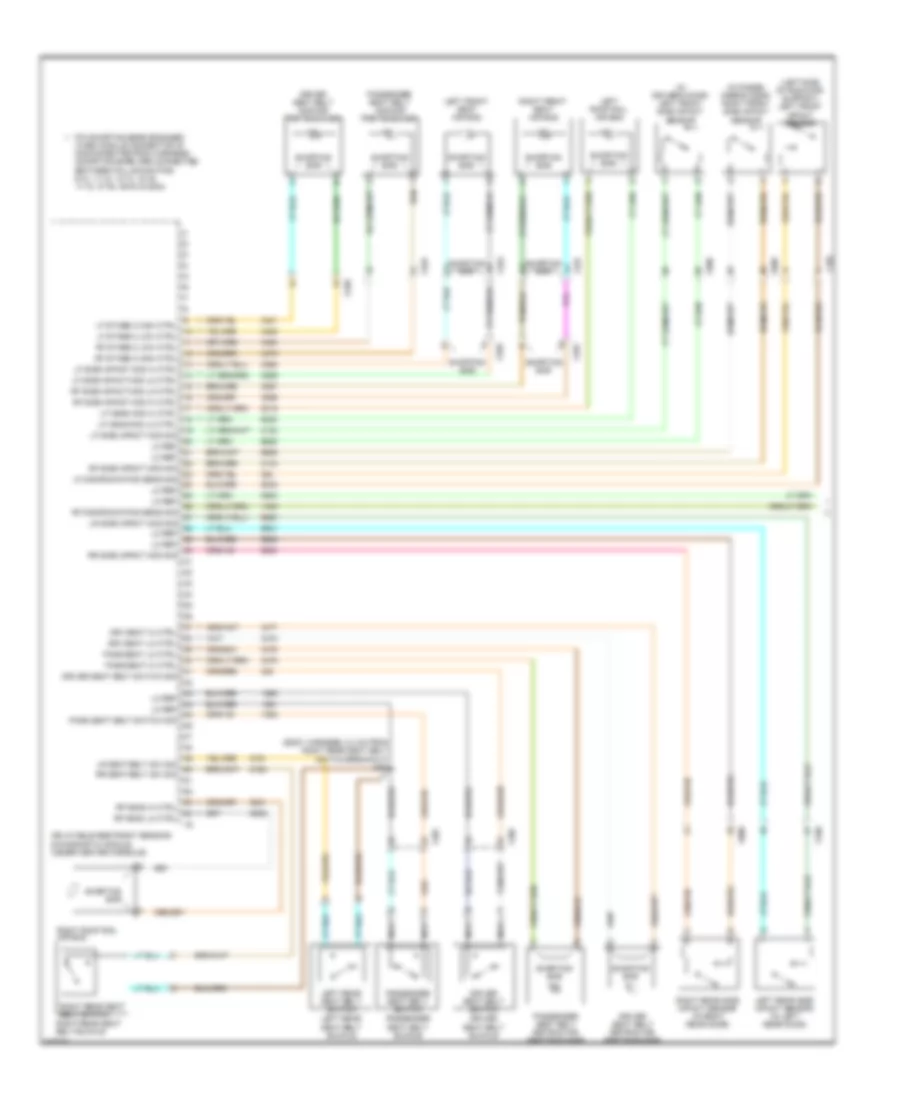
Anti-lock Brakes Wiring Diagram (2 of 2) for Chevrolet Volt 2011
List of elements for Anti-lock Brakes Wiring Diagram (2 of 2) for Chevrolet Volt 2011:
- Body control module (under right side of dash)
- Brake control brake pedal position sensor (behind left side of dash)
- Brake fluid level switch (master cylinder assembly)
- Brake ind
- Brake pedal position sensor (top of brake pedal assembly)
- Brk pdl travel sens 1 hi ref
- Brk pdl travel sens 1 sig
- Brk pdl travel sens 2 sig
- Combined vehicle inertial sens sply volt
- Computer data lines system
- Display
- G117 (near left strut tower)
- G204 (behind center of dash)
- G406 (right side of luggage compt)
- Gnd
- Hi spd gmlan serial data (+)
- Hi spd gmlan serial data (-)
- Hi spd gmlan serial data +
- Hi spd gmlan serial data -
- Instrument cluster
- J304 (body harness, 10 cm from x320)
- Lo ref
- Lo spd gmlan serial data
- Logic
- Multi-axis acceleration sensor (under center console)
- Steering angle sensor (top of steering column, behind steering wheel)
- Tcs/ esc ind
- X225
ANTI-THEFT
Forced Entry Wiring Diagram, with Passive Keyless Entry (1 of 2) for Chevrolet Volt 2011
List of elements for Forced Entry Wiring Diagram, with Passive Keyless Entry (1 of 2) for Chevrolet Volt 2011:
- (behind center of dash) keyless entry antenna
- (left side of engine compt) underhood fuse block
- (under center console) center console rear keyless entry antenna
- 87a
- Actr lck ctrl 2
- Actr rtn
- Actr unlck ctrl
- Ajar sw sig (1)
- Body control module (under right side of dash)
- Bus 3
- Computer data lines system
- Door lock relay
- Dr lck ctrl (2)
- Driver door latch assembly (center rear of driver's door)
- Driver window motor (driver's door)
- G103 (front of left frame rail)
- G204 (behind center of dash)
- G301 (under driver's door sill trim)
- G405 (right side of luggage compt)
- Gmlan ser data (+)
- Gmlan ser data (-)
- Gnd
- Headlights system
- Hi intr ant sig 1
- Hi intr ant sig 2
- Hi intr ant sig 3
- Horns system
- Ign 1v
- J514
- Keyless entry control module (right rear corner of luggage compt)
- Lck sig
- Lf dr ajar sw sig
- Lh hdlp lo sply volt
- Logic
- Low intr ant sig 1
- Low intr ant sig 2
- Low intr ant sig 3
- Low ref
- Pos volt
- Power distribution system
- Radio/hvac controls
- Rcv sig
- Remote control door lock receiver (front center of headliner)
- Rh hdlp lo sply volt
- Rly ctrl
- Serial data
- Sply volt
- Sw sig 2
- Trans sig
- Unlck sig
- Vehicle on/off switch
- X225
- X275
- X311
- X315
- X500
Forced Entry Wiring Diagram, with Passive Keyless Entry (2 of 2) for Chevrolet Volt 2011
List of elements for Forced Entry Wiring Diagram, with Passive Keyless Entry (2 of 2) for Chevrolet Volt 2011:
- (28 cm from x700 breakout) j308
- (left rear door harness, 21.5 cm from window motor left rear breakout) j715
- (right rear door harness, 11.5 cm from window motor right rear breakout) j815
- (under rear of center console) rear compartment keyless entry antenna
- Bus 3
- Bus 4
- Computer data lines system
- Display
- G302 (under front passenger's door sill trim)
- G403 (rear of luggage compt)
- G406 (right side of luggage compt)
- Hot at all times
- Instrument cluster
- J309 (18 cm from x700 breakout)
- J310
- Left rear door latch assembly (center rear of left rear door)
- Left rear window switch
- Lo spd gmlan serial data
- Logic
- Lr dr ajar sw sig
- Passenger door latch assembly (center rear of front passenger's door)
- Passenger window switch
- Peps fuse 10a
- Rear body fuse block (left rear corner of luggage compt)
- Rf dr ajar sw sig
- Right rear door latch assembly (center rear of right rear door)
- Right rear window switch
- Rr dr ajar sw sig
- X600
- X700
- X800
Forced Entry Wiring Diagram, without Passive Keyless Entry for Chevrolet Volt 2011
List of elements for Forced Entry Wiring Diagram, without Passive Keyless Entry for Chevrolet Volt 2011:
- (28 cm from x700 breakout) j308
- (8.5 cm from x700 breakout) j310
- (front of left frame rail)
- (left rear breakout 21.5 cm from window motor) j715
- (left side of engine compt) underhood fuse block
- (right rear breakout 11.5 cm from window motor) j815
- (under driver's door sill trim) g301
- 87a
- Actr lck ctrl 2
- Actr rtn
- Actr unlck ctrl
- Body control module (under right side of dash)
- Bus 3
- Bus 4
- Computer data lines system
- Display
- Door lock relay
- Dr lck ctrl (2)
- Driver door latch assembly (center rear of driver's door)
- Driver window motor (driver's door)
- G103
- G204 (behind center of dash)
- G302 (under front passenger's door sill trim)
- G403 (rear of luggage compt)
- G406 (right side of luggage compt)
- Gmlan ser data (+)
- Gmlan ser data (-)
- Headlights system
- Horn rly ctrl
- Horns system
- Instrument cluster
- J309 (18 cm from x700 breakout)
- J514
- Lck sig
- Left rear door latch assembly (center rear of left rear door)
- Left rear window switch
- Lh hdlp lo sply volt
- Lo spd gmlan serial data
- Logic
- Lr dr ajar sw sig
- Passenger door latch assembly (center rear of front passenger's door)
- Passenger window switch
- Radio/hvac controls
- Rcv sig
- Remote control door lock reciever (front center of headliner)
- Rf dr ajar sw sig
- Rh hdlp lo sply volt
- Right rear door latch assembly (center rear of right rear door)
- Right rear window switch
- Rly ctrl
- Rr dr ajar sw sig
- Sply volt
- Trans sig
- Unlck sig
- X225
- X311
- X500
- X600
- X700
- X800
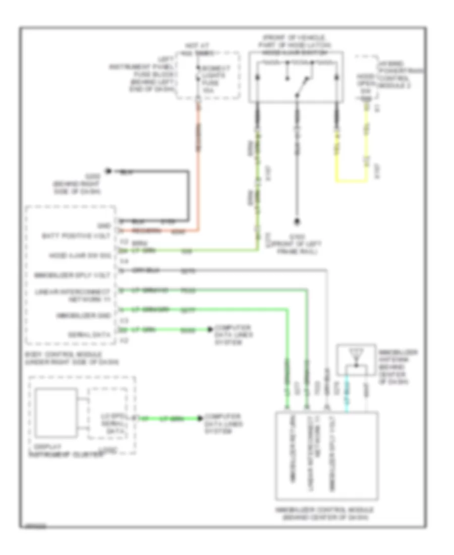
Pass-Key Wiring Diagram for Chevrolet Volt 2011
List of elements for Pass-Key Wiring Diagram for Chevrolet Volt 2011:
- (front of vehicle, part of hood latch) hood ajar switch
- Batt positive volt
- Bcm/ext lights fuse 15a
- Body control module (under right side of dash)
- Computer data lines system
- Display
- G103 (front of left frame rail)
- G202 (behind right side of dash)
- Gnd
- Hood ajar sw sig
- Hood open sw sig
- Hot at all times
- Hybrid powertrain control module 2
- Immobilizer antenna (behind center of dash)
- Immobilizer control module (behind center of dash)
- Immobilizer gnd
- Immobilizer return
- Immobilizer sply volt
- Instrument cluster
- Left instrument panel fuse block (behind left end of dash)
- Linear interconnect
- Linear interconnect network 11
- Lo spd serial data
- Logic
- Nca
- Network 11
- Serial data
- X107
- X275
BODY CONTROL MODULES
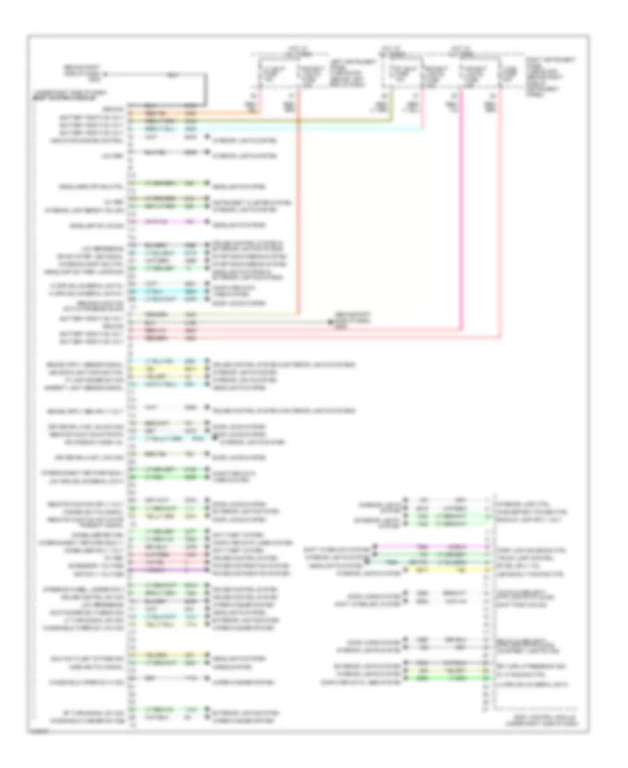
Body Control Modules Wiring Diagram (1 of 2) for Chevrolet Volt 2011
List of elements for Body Control Modules Wiring Diagram (1 of 2) for Chevrolet Volt 2011:
- (behind right side of dash) g202
- (or 737)
- (under right side of dash)
- (under right side of dash) body control module
- 12v ref
- Accessory voltage
- Ambient light sensor signal
- Anti-theft system
- Apo/ext lights fuse 15a
- Backup lamp sply volt
- Battery positive volt
- Bcm/ext lights fuse 15a
- Body control module
- Charging comp ind ctrl
- Computer data lines system
- Cruise control sw sig
- Cruise control system
- Cruise control system & exterior lights systems
- Door locks system
- Driver dr lk sw lock sig
- Driver dr lk sw unlock sig
- Exterior lights system
- Ground
- Hazard switch signal
- Hdlp dimmer sw hi beam sig
- Hdlp sw flash to pass sig
- Headlamp sw on sig
- Headlamp sw park lamps sig
- Headlamps off sig ctrl
- Headlights system
- Headlights system & exterior lights systems
- Hi spd gmlan serial data(+)
- Hi spd gmlan serial data(-)
- Horn switch signal
- Horns system
- Hot at all times
- Ign mode sw mode vol
- Ign sw start led signal
- Ignition 1 voltage
- Immobilizer return
- Immobilizer sply volt
- Inadvertent power ctrl
- Indicator dimming control
- Instrument cluster system
- Interconnect network bus 11
- Interconnect network bus 4
- Interior lamp ctrl
- Interior lamp defeat sw sig
- Interior lights system
- Ip lamp dimmer sw sig
- Ip lp dimming ctrl
- Lcks fuse 20a
- Led backlight dimming ctrl
- Led backlt dimming ctrl
- Left instrument panel fuse block (behind left end of dash)
- Lf turn signal sw sig
- Lo spd gmlan serial data
- Low ref
- Low reference
- Low spd gmlan serial data
- Lr child security mtr lock status sig
- Lt hdlp fuse 15a
- Park lock solenoid ctrl
- Power distribution system
- Remote function actr rtn
- Remote function actuator receive sig
- Remote function actuator transmit signal
- Remote function sply volt
- Rf drl sply vol
- Rf turn signal sw sig
- Right instrument panel fuse block (behind right side of instrument panel)
- Rr child security mtr lock status sig courtesy lamp sw sig
- Rr turn lp feedback sig
- Rt hdlp fuse 15a
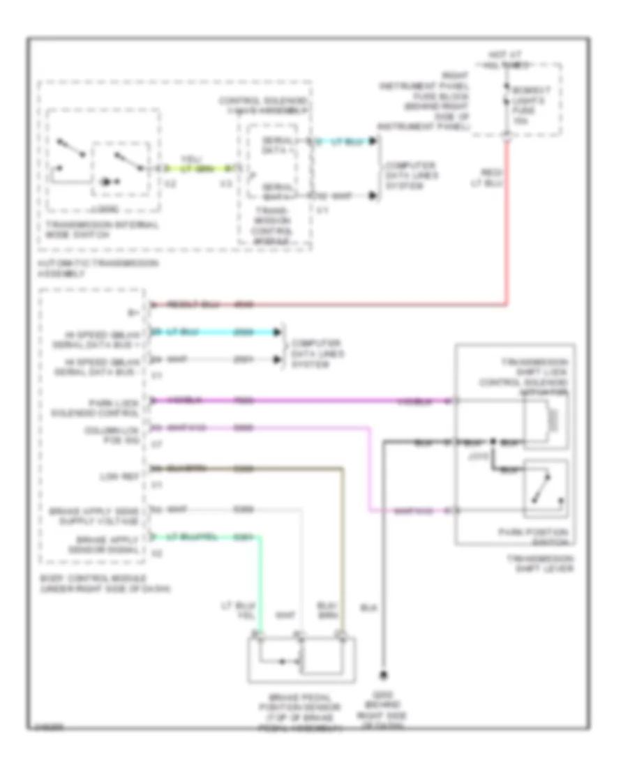
- Shift interlock system
- Shift position sig
- Starting/charging system
- Steering wheel ladder sig 2
- Trunk lamp control
- Windshield washer sw sig
- Windshield wiper sw hi sig
- Windshield wiper sw low sig
- Wiper/washer system
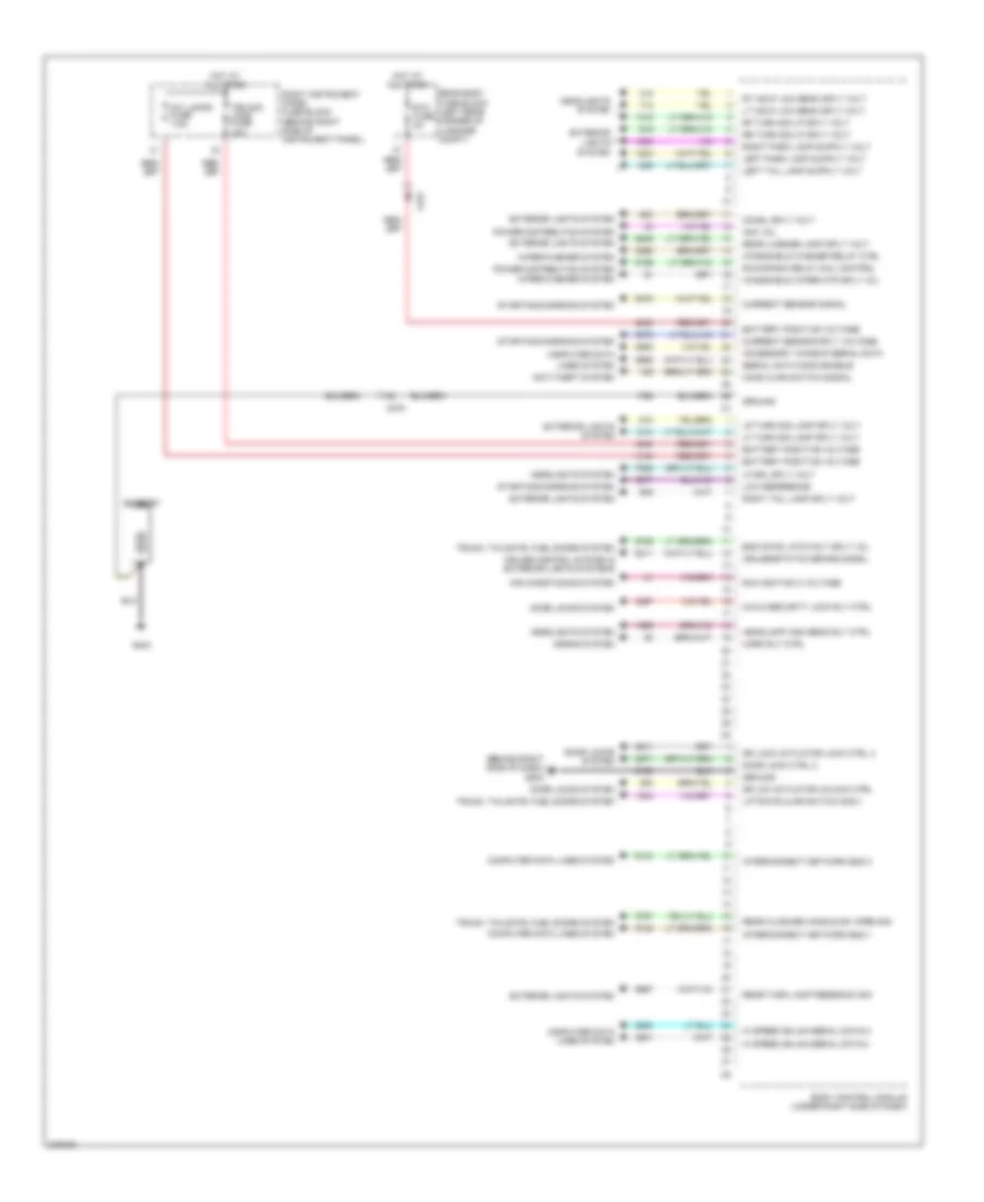
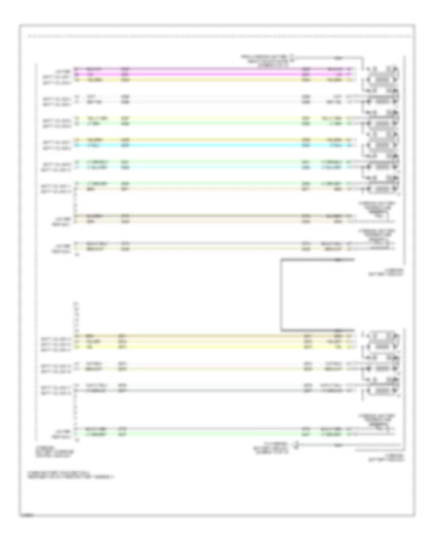
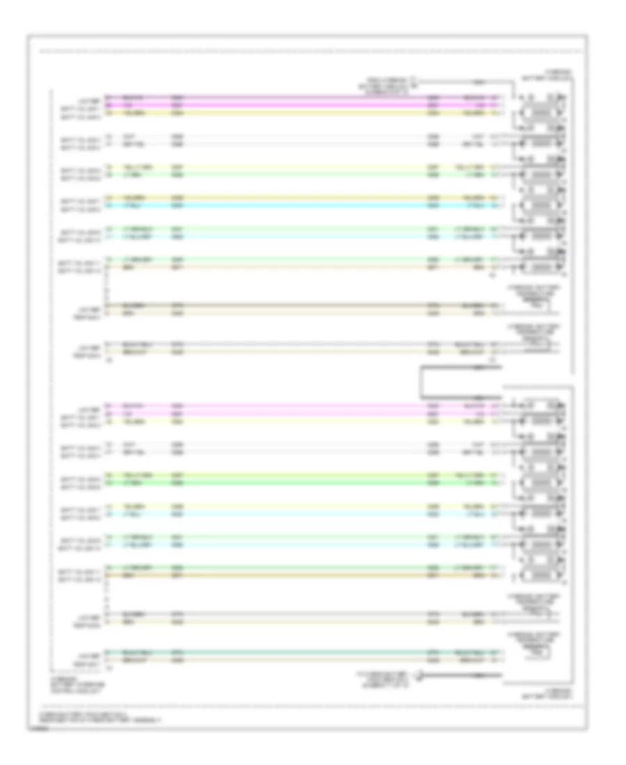
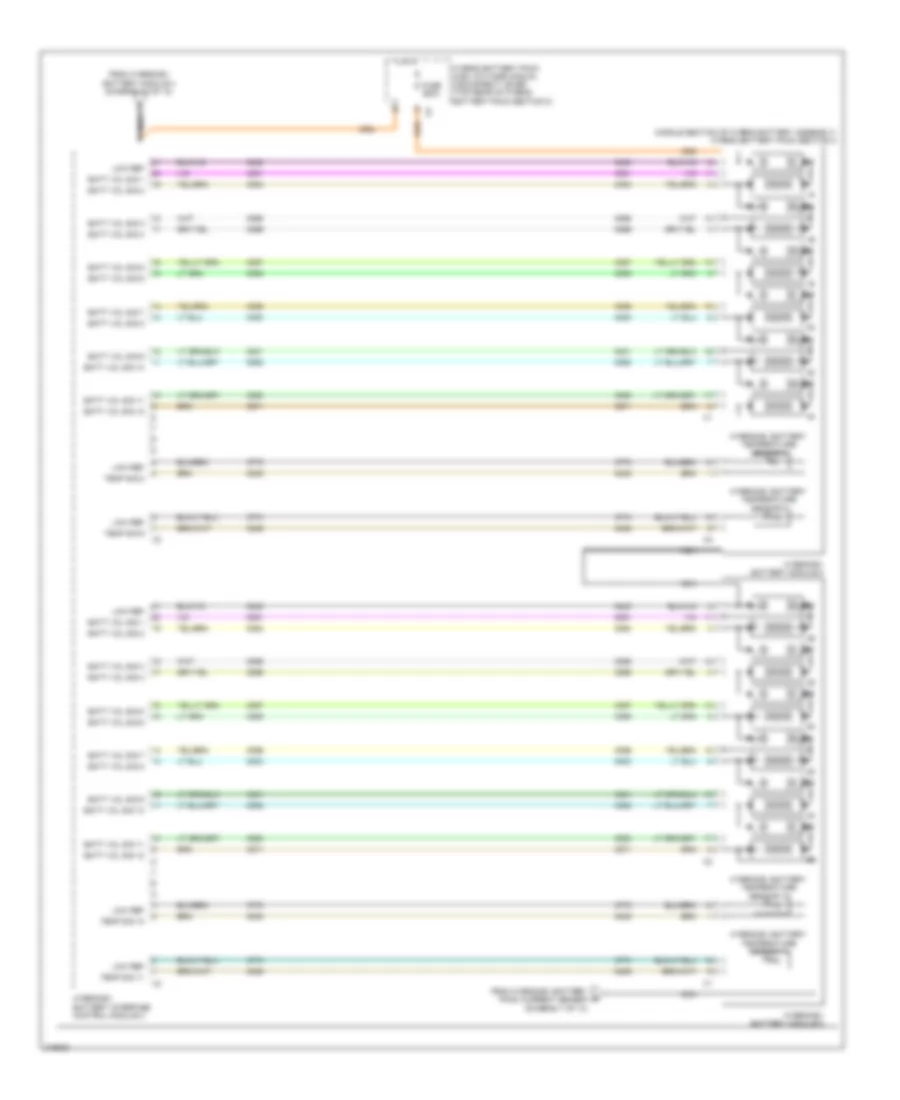
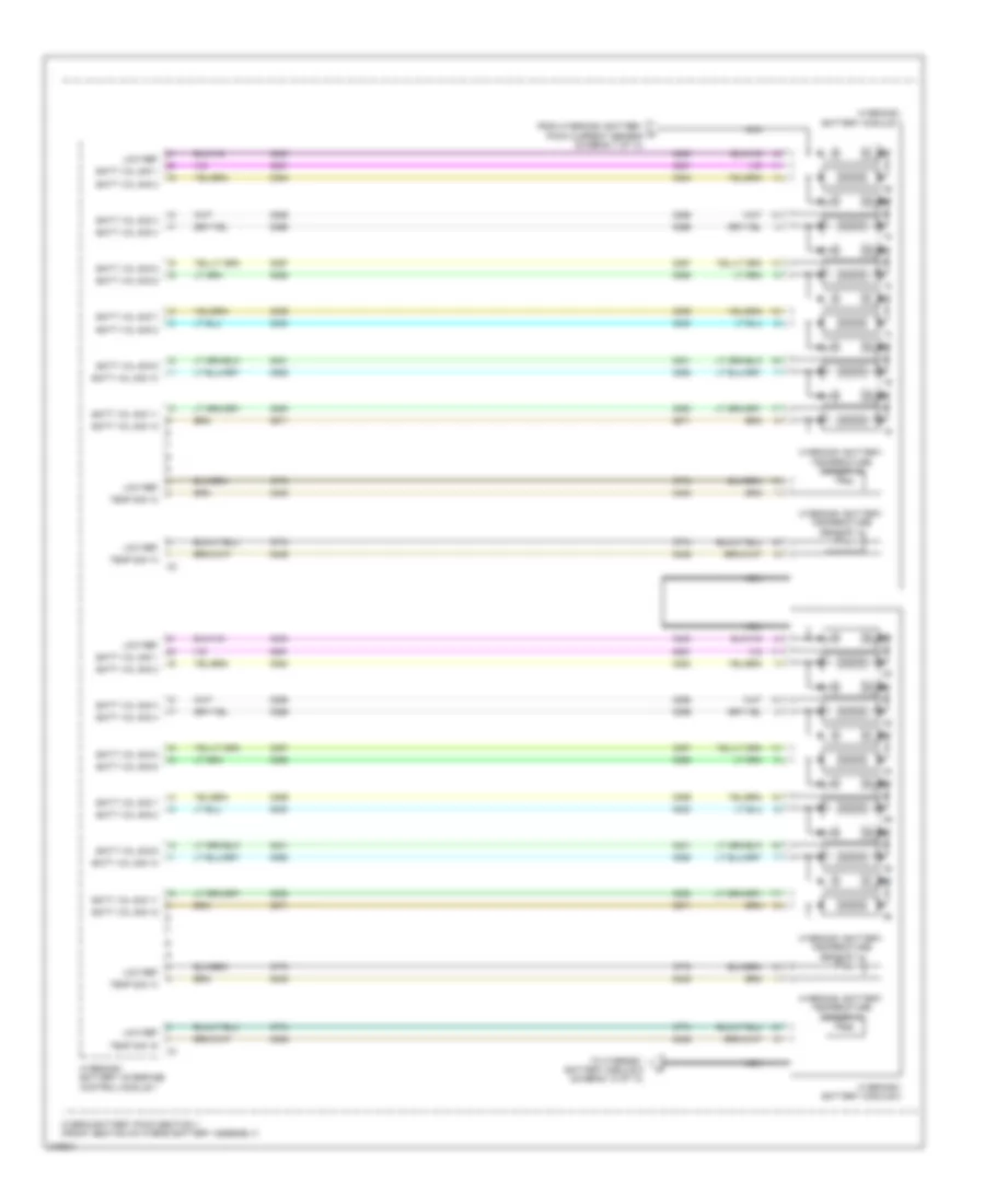
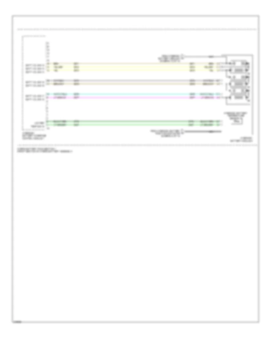
Body Control Modules Wiring Diagram (2 of 2) for Chevrolet Volt 2011
List of elements for Body Control Modules Wiring Diagram (2 of 2) for Chevrolet Volt 2011:
- (behind right side of dash) g202
- Acc vol
- Accessory wakeup serial data
- Air conditioning system
- Anti-theft system
- Battery
- Battery positive voltage
- Body control module (under right side of dash)
- Child security lock rly ctrl
- Chmsl sply volt
- Computer data
- Computer data lines system
- Cruise control system & exterior lights systems
- Cruise/etc/tcc brake signal
- Current sensor signal
- Current sensor sply voltage
- Door lock ctrl 2
- Door locks system
- Dr lck actuator unlock ctrl
- Dr lock actuator lock ctrl 2
- End gate latch rly sply vol
- Exterior
- Exterior lights system
- G404
- Ground
- Headlamp high beam rly ctrl
- Headlights system
- Hi speed gmlan serial data(+)
- Hi speed gmlan serial data(-)
- Hood ajar switch signal
- Horn rly ctrl
- Horns system
- Hot at all times
- Int lamps fuse 7.5a
- Interconnect network bus 1
- Interconnect network bus 3
- Lf drl sply volt
- Lf turn sig lamp sply volt
- Liftgate ajar switch sig(1)
- Lights system
- Lines system
- Low reference
- Lr turn sig lamp sply volt
- Lt hdlp low beam sply volt
- Power distribution system
- Rear body fuse block (left rear corner of luggage compt)
- Rear closure handle sw open sig
- Rear license lamp sply volt
- Rear turn lamp feedback sig
- Rf turn sig lp sply volt
- Right instrument panel fuse block (behind right side of instrument panel)
- Right tail lamp sply volt
- Rr turn sig lp sply volt
- Rt hdlp low beam sply volt
- Run ignition 3 voltage
- Run/crank relay coil control
- Rvc fuse 5a
- Serial data comm enable
- Starting/charging system
- Trn sig lcks fuse 15a
- Trunk, tailgate, fuel doors system
- Windshield washer relay ctrl
- Windshield wiper mtr sply vol
- Wiper/washer system
- X275
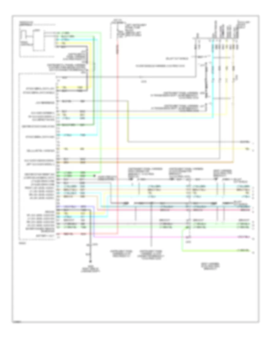
COMPUTER DATA LINES
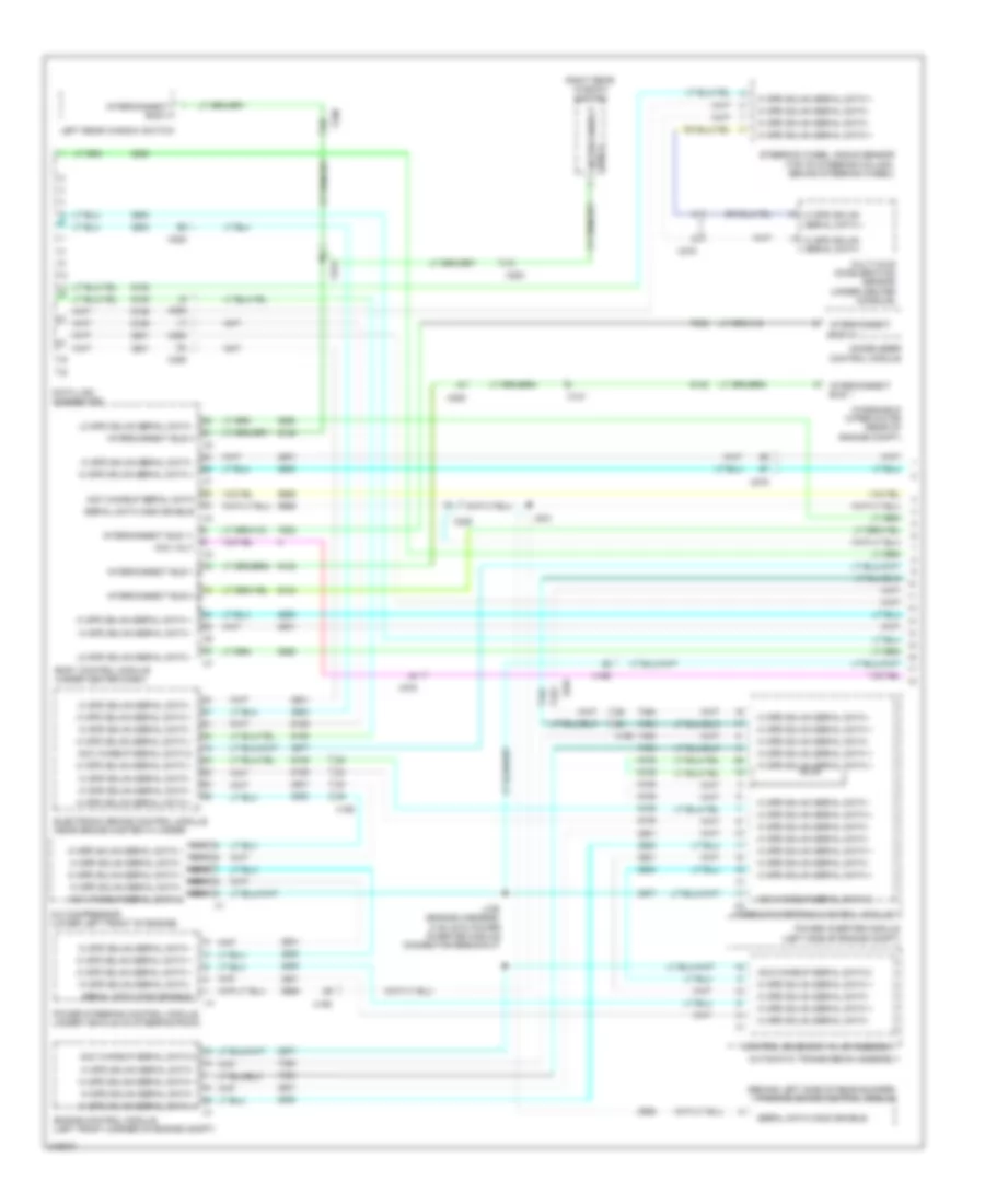
Computer Data Lines Wiring Diagram (1 of 3) for Chevrolet Volt 2011
List of elements for Computer Data Lines Wiring Diagram (1 of 3) for Chevrolet Volt 2011:
- (behind left side of rear bumper) parking brake control module
- A/c compressor (lower left front of engine)
- Acc volt
- Acc wakeup serial data
- Acc wakeup serial data 2
- Acc wakeup serial data 2 hi spd gmlan serial data - hi spd gmlan serial data + hi spd gmlan serial data - hi spd gmlan serial data + x1
- Automatic transmission assembly
- Body control module (under center dash)
- Control solenoid valve assembly
- Data link connector
- Electronic brake control module (near brake master cylinder)
- Engine control module (left front corner of engine compt)
- Hi spd gmlan serial data +
- Hi spd gmlan serial data -
- Hybrid powertrain control module1
- Immobilezer control module
- Interconnect bus 1
- Interconnect bus 11
- Interconnect bus 3
- Interconnect bus 4
- J129 (engine harness, 5 cm into power inverter module connector breakout)
- J303
- Left rear window switch
- Lo spd gmlan serial data -
- Multi-axis acceleration sensor (under center console)
- Nca hi spd gmlan serial data + nca hi spd gmlan serial data - nca hi spd gmlan serial data + nca hi spd gmlan serial data - nca acc wakeup serial data 2
- Power inverter module (left side of engine compt)
- Power steering control module (under vehicle on steering rack)
- Right rear window switch
- Serial data comm enable
- Steering wheel angle sensor (top of steering column, behind steering wheel)
- Windshield wiper motor (rear of engine compt)
- X107
- X190
- X225
- X275
- X700
- X800
Computer Data Lines Wiring Diagram (2 of 3) for Chevrolet Volt 2011
List of elements for Computer Data Lines Wiring Diagram (2 of 3) for Chevrolet Volt 2011:
- (behind left side of rear bumper) parking brake control module
- (body harness, 20.7 cm from x600 breakout)
- (forward lamp harness, 14 cm from x105 breakout)
- (forward lamp harness, 18.5 cm from x105 breakout)
- (not used)
- (right front corner of engine compt) battery charger
- (right side of luggage compt) fuel pump control module
- 14v power module (center of luggage compt)
- Acc volt
- Acc wakeup serial data 2
- Acc wakeup serial data managment comm enable hi volt enrergy
- Auxiliary data connector
- Battery charger control module
- Battery energy control module
- Bus 3 interconnect
- Can bus hi serial data
- Can bus lo serial data
- Driver window motor (driver's door)
- Driver window switch
- Hi spd gmlan serial data +
- Hi spd gmlan serial data -
- Hybrid powertrain control module 2
- Hybrid/ev battery pack
- Interconnect bus 3
- J107
- J108
- J302
- J402 (body harness, 32 cm from left rear seat belt switch)
- J515 (left front door harness, 8.3 cm from x510 breakout)
- Keyless entry control module (right rear corner of luggage compt)
- Lo spd gmlan serial data
- Lo spd gmlan serial data +
- Managment comm enable hi volt enrergy
- Passenger window switch
- Pnk
- Serial data comm enable
- Tan
- Telematics communication interface control module (behind right side of dash)
- X105
- X225
- X275
- X500
- X505
- X600
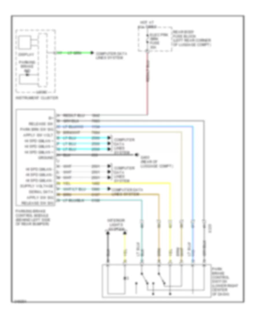
Computer Data Lines Wiring Diagram (3 of 3) for Chevrolet Volt 2011
List of elements for Computer Data Lines Wiring Diagram (3 of 3) for Chevrolet Volt 2011:
- (not used)
- Coolant heater control module (rear of engine compt)
- Front & rear parking assist control module (left rear corner of luggage compt)
- Hvac control module (center of dash)
- Inflatable restraint sensing and diagnostic module (under center console)
- Instrument cluster
- Jx300 (luggage compt, behind left trim panel)
- Jx301 (behind instrument panel)
- Linear interco- nnect network
- Lo spd gmlan serial data
- Nca lo spd gmlan serial data
- Nca serial data lo spd gmlan
- Passenger presence detection module (under rear of passe- nger's seat)
- Radio
- Radio/hvac control
- Seat heating control module (under front of driver's seat)
- Serial data lo spd gmlan
- W/ front seat heater
- W/ parking assist sensor indicator
- X275
- X320
- X325
COOLING FAN
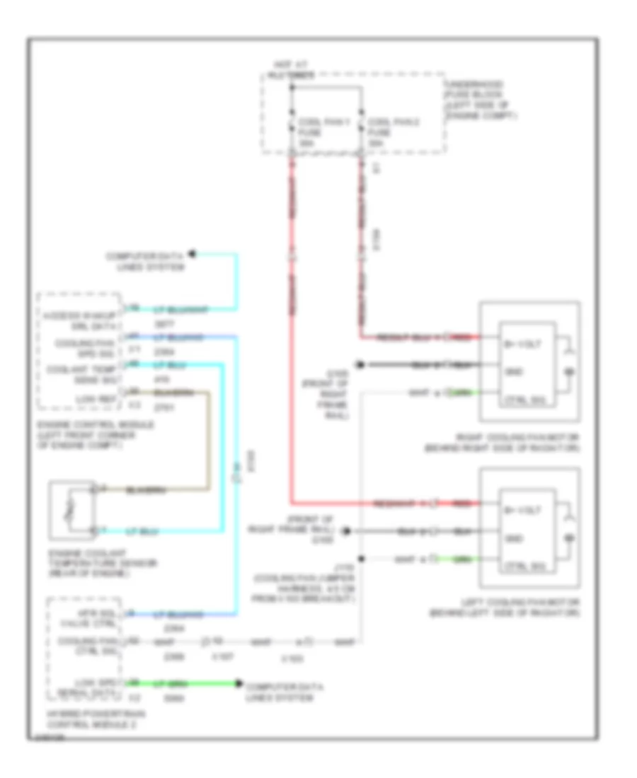
Cooling Fan Wiring Diagram for Chevrolet Volt 2011
List of elements for Cooling Fan Wiring Diagram for Chevrolet Volt 2011:
- (front of right frame rail) g105
- Access wakup srl data
- B+ volt
- Computer data lines system
- Cool fan 1 fuse 30a
- Cool fan 2 fuse 30a
- Coolant temp sens sig
- Cooling fan ctrl sig
- Cooling fan spd sig
- Ctrl sig
- Engine control module (left front corner of engine compt)
- Engine coolant temperature sensor (rear of engine)
- G105 (front of right frame rail)
- Gnd
- Hot at all times
- Htr sol valve ctrl
- Hybrid powertrain control module 2
- J110 (cooling fan jumper harness, 4.5 cm from x103 breakout)
- Left cooling fan motor (behind left side of radiator)
- Low ref
- Low spd serial data
- Red
- Right cooling fan motor (behind right side of radiator)
- Underhood fuse block (left side of engine compt)
- X103
- X104
- X107
- X190
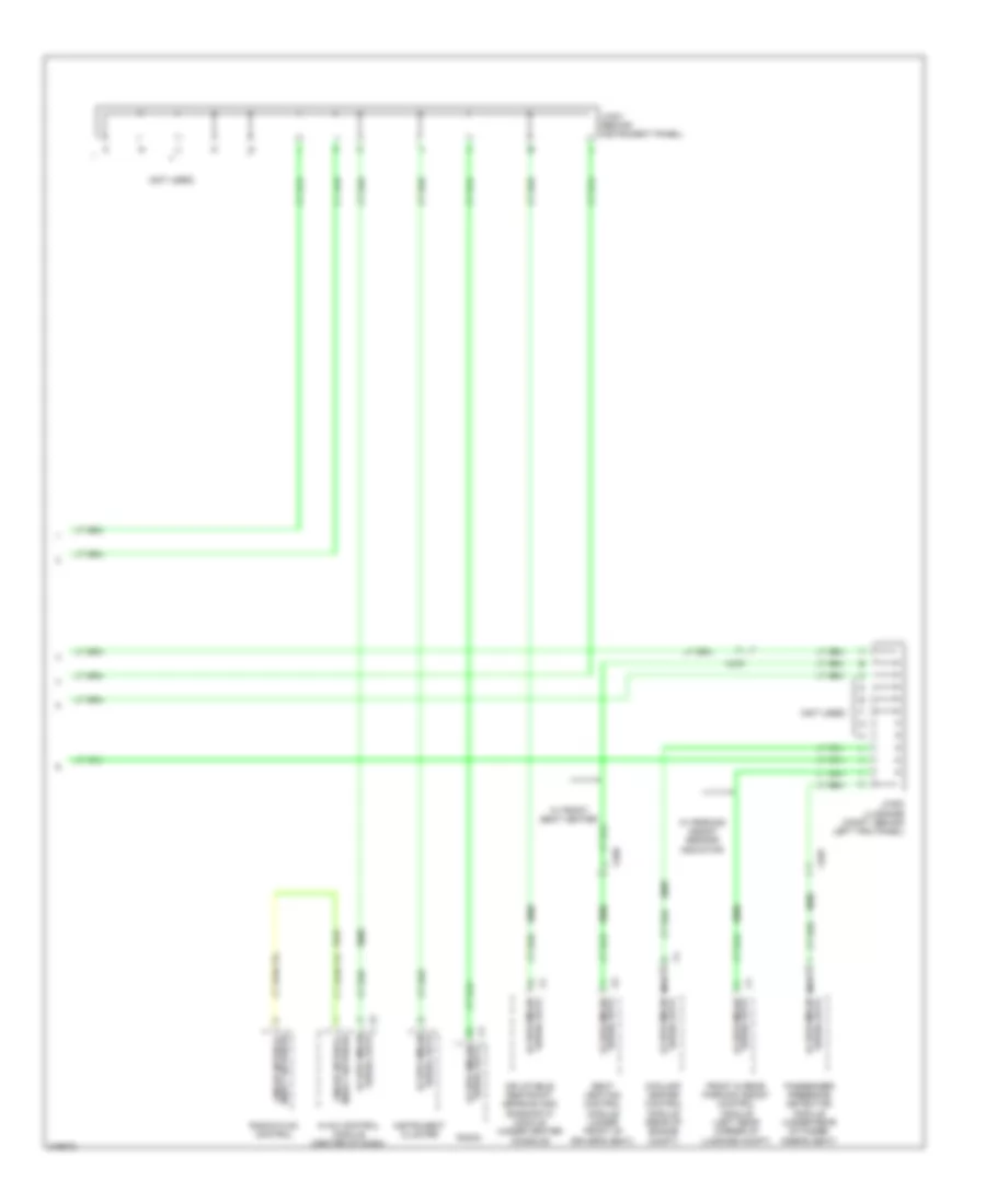
Hybrid Cooling Fan Wiring Diagram for Chevrolet Volt 2011
List of elements for Hybrid Cooling Fan Wiring Diagram for Chevrolet Volt 2011:
- (front of right frame rail) g105
- (right side of luggage compt) g405
- 14v power module (center of luggage compt)
- Apm fan fuse 15a
- B+ volt
- Computer data lines system
- Fan ctrl
- Fan enable
- Fan feed- back sig
- Gnd
- Hot at all times
- Hybrid electronics coolant pump (bottom front left corner of engine compt)
- Hybrid electronics coolant temperature sensor (left front of engine compt, on hybrid electronic radiator)
- Hybrid powertrain control module 2
- Low ref
- Low spd serial data
- Mtr ctrl
- Mtr enable
- Mtr feed- back sig
- Pwr-elec cool pump fuse 10a
- Rear body fuse block (left rear corner of luggage compt)
- Sens sig
- Underhood fuse block (left side of engine compt)
- X102
- X103
- X107
- X109
- X190
CRUISE CONTROL
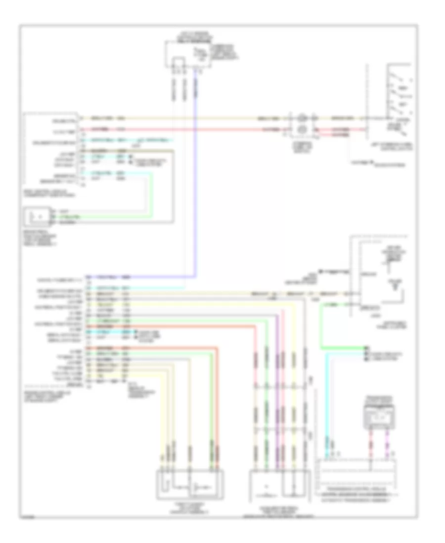
Cruise Control Wiring Diagram for Chevrolet Volt 2011
List of elements for Cruise Control Wiring Diagram for Chevrolet Volt 2011:
- 12 volt ref
- 5v ref
- Acc pedal position sig 1
- Acc pedal position sig 2
- Accelerator pedal position sensor (near accelerator pedal bracket)
- Automatic transmission assembly
- Body control module (under right side of dash)
- Brake pedal position sensor (top of brake pedal assembly)
- Cancel
- Check engine ind ctrl
- Computer data lines system
- Control solenoid valve assembly
- Cruise ctrl
- Cruise ind
- Cruise switch
- Cruise/etc/tcc br sig
- Cruise/etc/tcc brk sig
- Data bus +
- Data bus -
- Driver information center display
- Ecm fuse 15a
- Engine control module (left front corner of engine compt)
- G113 (rear of transmission assembly)
- G204 (behind center of dash)
- Ground
- Hot w/ engine controls ignition relay energized
- Instrument panel cluster
- Left steering wheel control switch
- Logic
- Low ref
- Main rly fused sply (1)
- Red
- Res+
- Sensor sig
- Sensor sply volt
- Ser data
- Serial data bus +
- Serial data bus -
- Set-
- Sound systems
- Steering wheel air bag coil
- Tac ctrl close
- Tac ctrl open
- Throttle body (on intake manifold assembly)
- Tp sens 1 sig
- Tp sens 2 sig
- Transmission control module
- Transmission output shaft speed sensor
- Underhood fuse block (left side of engine compt)
- X190
- X225
- X275
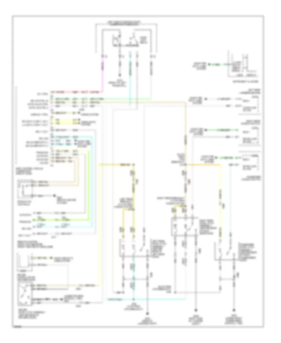
DEFOGGERS
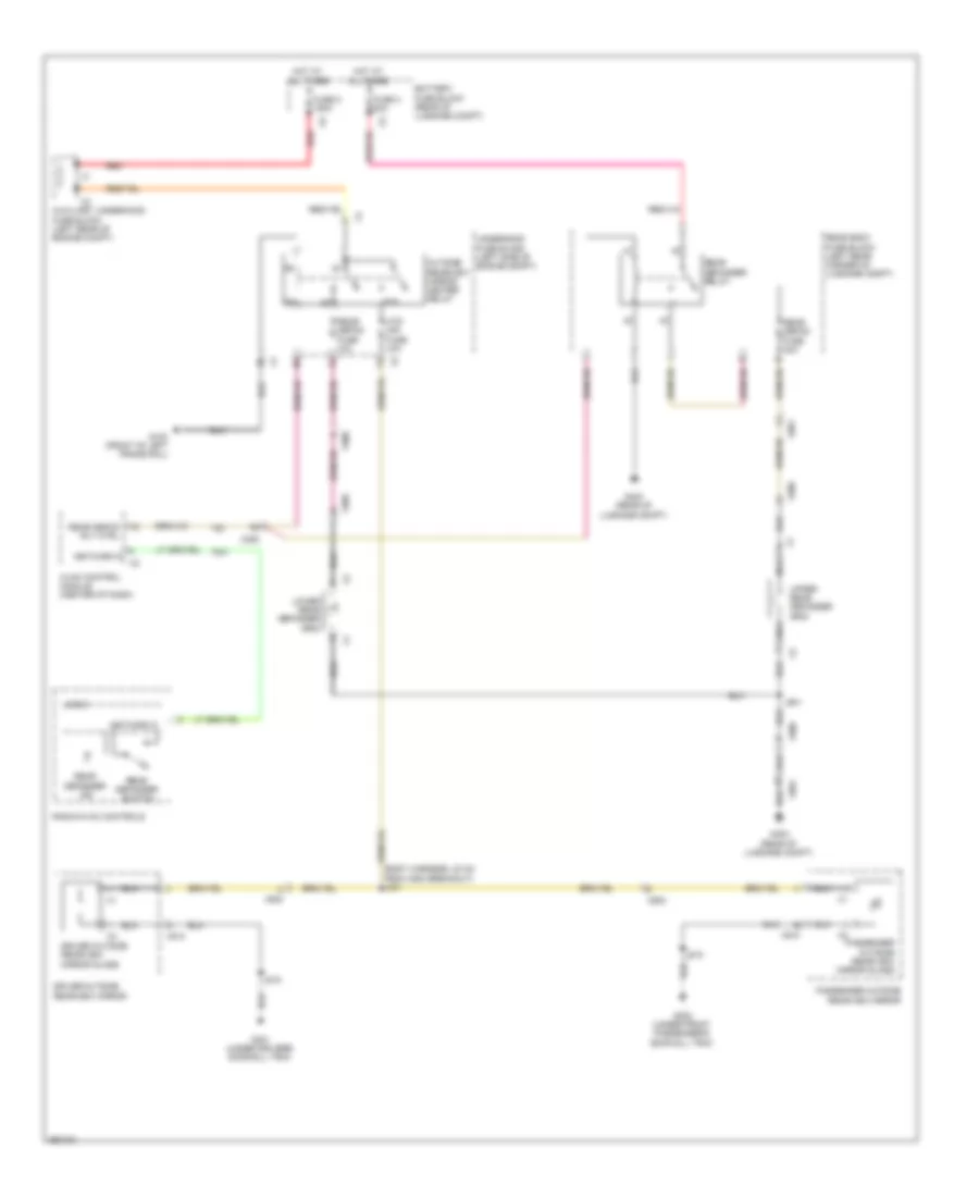
Defoggers Wiring Diagram for Chevrolet Volt 2011
List of elements for Defoggers Wiring Diagram for Chevrolet Volt 2011:
- (body harness, 23 cm from x500 breakout) j301
- 87a
- Auxiliary underhood fuse block (left rear of engine compt)
- Battery fuse block (rear of luggage compt)
- Driver outside rearview mirror
- Driver outside rearview mirror glass
- Fuse 3 80a
- Fuse 5 150a
- G103 (front of left frame rail)
- G301 (under driver's door sill trim)
- G302 (under front passenger's door sill trim)
- G403 (rear of luggage compt)
- Hot at all times
- Htd mir fuse 10a
- Hvac control module (center of dash)
- J515
- J615
- J901
- Logic
- Lower rear defogger grid
- Nca
- Network 9
- Outside rearview mirror heater relay
- Passenger outside rearview mirror
- Passenger outside rearview mirror glass
- Radio/hvac controls
- Rear body fuse block (left rear corner of luggage compt)
- Rear defog fuse 10a
- Rear defog fuse 40a
- Rear defog rly ctrl
- Rear defogger ind
- Rear defogger relay
- Rear defogger switch
- Red
- Underhood fuse block (left side of engine compt)
- Upper rear defogger grid
- X225
- X500
- X510
- X600
- X610
- X900
- X901
- X905
- X906
ELECTRONIC POWER STEERING
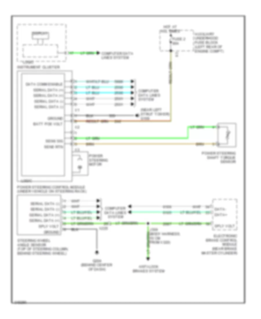
Electronic Power Steering Wiring Diagram for Chevrolet Volt 2011
List of elements for Electronic Power Steering Wiring Diagram for Chevrolet Volt 2011:
- (near left strut tower) g109
- Anti-lock brakes system
- Auxiliary underhood fuse block (left rear of engine compt)
- Batt pos volt
- Computer data lines system
- Data comm enable
- Data+
- Data-
- Display
- Electronic brake control module (near brake master cylinder)
- Fuse 2 80a
- G204 (behind center of dash)
- Ground
- Hot at all times
- Instrument cluster
- J304 (body harness, 10 cm from x320)
- Logic
- Power steering control module (under vehicle on steering rack)
- Power steering motor
- Power steering shaft torque sensor
- Sens rtn
- Sens sig
- Serial data (+)
- Serial data (-)
- Sply volt
- Steering wheel angle sensor (top of steering column, behind steering wheel)
- X225
ENGINE PERFORMANCE
1.4L VIN 4
1.4L VIN 4, Engine Controls Wiring Diagram (1 of 6) for Chevrolet Volt 2011
List of elements for 1.4L VIN 4, Engine Controls Wiring Diagram (1 of 6) for Chevrolet Volt 2011:
- (left front corner of engine compt) engine control module (ecm)
- (rear of fuel tank) evaporative emission system leak detection pump assembly
- (top of fuel tank) fuel tank pressure (ftp) sensor
- 5 volt ref
- Check engine ind ctrl
- Cluster system instrument
- Computer data lines system
- Cylinder shutoff sol crtl
- Engine coolant temp sens sig
- Engine coolant temperature (ect) sensor (rear of engine)
- Evap canister pur sol ctrl
- Evap emis leak detc pmp assm
- Evap emis leak detc pmp ref
- Evap emis leak detc pmp sig
- Evap emis vent sol vlv gnd
- Fuel tank press sens sig
- Fuel temp/comption sig
- H (not used)
- Ho2s high sig bank 1 sens 2
- Ho2s htr hi ctrl bank1 sens2
- Ho2s low sig bank 1 sens 2
- Instrument cluster
- Instrument cluster system
- J377 (evaporative emissions harness, 13.5 cm from x355 connector breakout)
- Lo spd gmlan serial data
- Logic
- Low ref
- Malfunc- tion ind
- Manfold absolt press sens sig
- Manifold absolute pressure (map) sensor (in intake manifold)
- Primary fuel lvl sens sig
- X190
- X225
- X350
- X351
1.4L VIN 4, Engine Controls Wiring Diagram (2 of 6) for Chevrolet Volt 2011
List of elements for 1.4L VIN 4, Engine Controls Wiring Diagram (2 of 6) for Chevrolet Volt 2011:
- (exhaust manifold) heated oxygen sensor 1
- (exhaust, downstream of catalytic converter) heated oxygen sensor 2
- (intake manifold assembly) evaporative emission (evap) purge solenoid valve
- (rear of fuel tank) evaporative emission vent solenoid valve
- Accelerator pedal position (app) sensor (near accelerator pedal bracket)
- Engine coolant radiator temperature sensor (right side of radiator)
- Exhaust camshaft position (cmp) actuator solenoid valve (left front of engine)
- Intake camshaft position (cmp) actuator solenoid valve (right front of engine)
- Mass air flow (maf)/intake air temperature sensor (intake, after air cleaner)
- Nca
- X102
- X190
- X225
1.4L VIN 4, Engine Controls Wiring Diagram (3 of 6) for Chevrolet Volt 2011
List of elements for 1.4L VIN 4, Engine Controls Wiring Diagram (3 of 6) for Chevrolet Volt 2011:
- 5 volt ref
- A/c rfgt pr sens sig
- Acc pedal pos sig 1
- Acc pedal pos sig 2
- Battery positive volt
- Ccm/vicm fuse 5a
- Check engine ind ctrl
- Computer data lines
- Cooling fans system
- Coolt temp sens 2 sig
- Cruise/etc/tcc brk sig
- Ecm fuse 15a
- Ecm fuse 5a
- Ecm/tcm fuse 5a
- Emis fuse 10a
- Engine control module (ecm) (left front corner of engine compt)
- Engine controls ignition relay
- Engine main rly ctrl
- Evel/ elcm fuse 10a
- Exterior lights system
- F p primary rly ctrl
- Fan rly ctrl low spd cooling
- Fscm fuse 15a
- Hot at all times
- Hot w/ ign run relay energized
- Hs gmlan + 1
- Hs gmlan + 3
- Hs gmlan - 1
- Hs gmlan - 3
- Ign coil fuse 15a
- In air temp sens sig
- Inj fuse 10a
- J125
- J128
- J376
- Lines system computer data
- Low ref
- Mas air flow sens sig
- Rear body fuse block (left rear corner of luggage compt)
- Run/crank ign 1 volt
- System
- Underhood fuse block (left side of engine compt)
- Wakeup serial data 2
- X190
1.4L VIN 4, Engine Controls Wiring Diagram (4 of 6) for Chevrolet Volt 2011
List of elements for 1.4L VIN 4, Engine Controls Wiring Diagram (4 of 6) for Chevrolet Volt 2011:
- (right side of engine) fuel injectors
- 5 volt ref
- Batt +
- Fuel
- Fuel press sens sig
- Fuel pump & level sensor assembly (top of fuel tank assembly)
- Fuel pump control module (right side of luggage compt)
- Fuel pump ctrl
- Fuel pump rly ctrl
- G106 (top left rear of engine)
- G405 (right side of luggage compt)
- Gnd
- Hs gmlan + 1
- Hs gmlan - 1
- Ignition coil module (top rear of engine)
- Low ref
- Nca
- Pump
- Run/crak ign 1 volt
- Serl data comm enbl
- Shield
- System data lines computer
- Underhood fuse block (left side of engine compt)
- X350
- X354
1.4L VIN 4, Engine Controls Wiring Diagram (5 of 6) for Chevrolet Volt 2011
List of elements for 1.4L VIN 4, Engine Controls Wiring Diagram (5 of 6) for Chevrolet Volt 2011:
- A/c refrigerant pressure sensor (right front of engine compt)
- Crankshaft position (ckp) sensor (lower right rear of engine)
- Exhaust camshaft position sensor (left front of cylinder head)
- Fuel pressure sensor (fuel line at right front of fuel tank)
- Intake camshaft position sensor (right front of cylinder head)
- Knock sensor (right side of engine)
- X102
- X355
1.4L VIN 4, Engine Controls Wiring Diagram (6 of 6) for Chevrolet Volt 2011
List of elements for 1.4L VIN 4, Engine Controls Wiring Diagram (6 of 6) for Chevrolet Volt 2011:
- (left front corner of engine compt)
- 5 volt ref
- Camshaft cam x sup volt 1
- Camshaft pos exhaust sens 1
- Camshaft pos in sens spy volt 1
- Camshaft pos intake sens 1
- Cmp phaser exhaust sol 1
- Cmp phaser intake sol 1
- Crankshaft 60x sens sig
- Crankshaft 60x sens volt
- Engine control module (ecm)
- Engine coolant thermostat heater (left front of engine)
- Fuel inj ctrl 1
- Fuel inj ctrl 2
- Fuel inj ctrl 3
- Fuel inj ctrl 4
- G113 (rear of transmission assembly)
- Ground
- Ho2s high sig bank 1 sens 1
- Ho2s htr low ctrl bank 1 sens 1
- Ho2s low sig bank 1 sens 1
- Ign ctrl 1
- Ign ctrl 2
- Ign ctrl 3
- Ign ctrl 4
- Instrument cluster system
- Knock sensor sig 1
- Low ref
- Oil pressure sw sig
- Powertrain main rly fuse sply 1
- Thermostat engine cool ctrl
- Throttle actuator ctrl close
- Throttle actuator ctrl open
- Throttle body assembly (on intake manifold assembly)
- Throttle position sensor sig 1
- Throttle position sensor sig 2
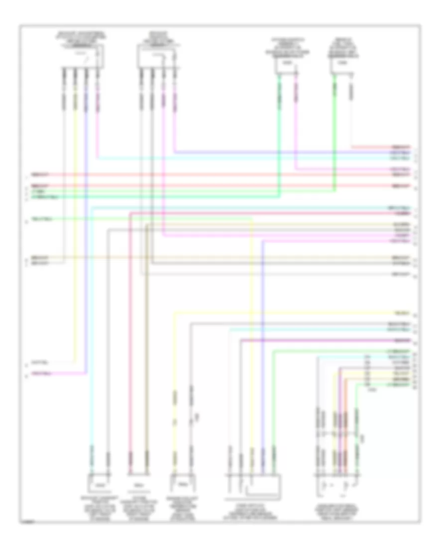
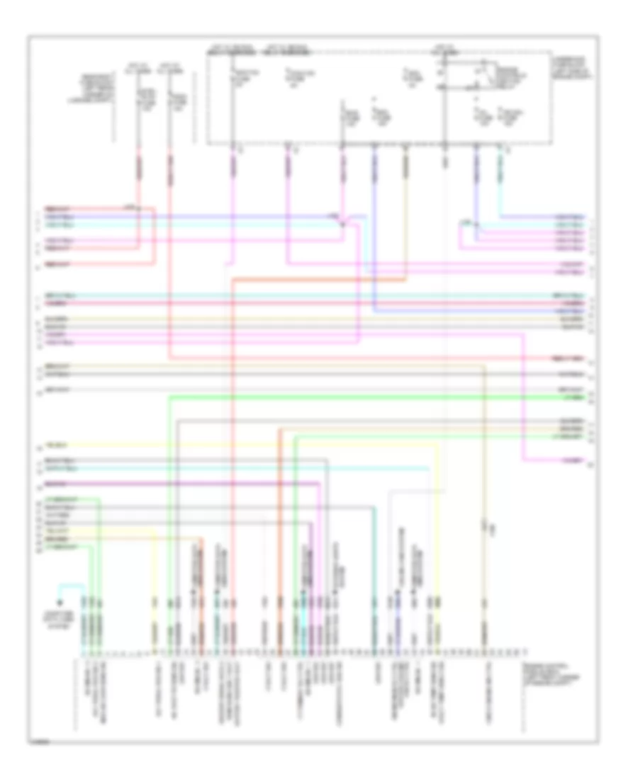
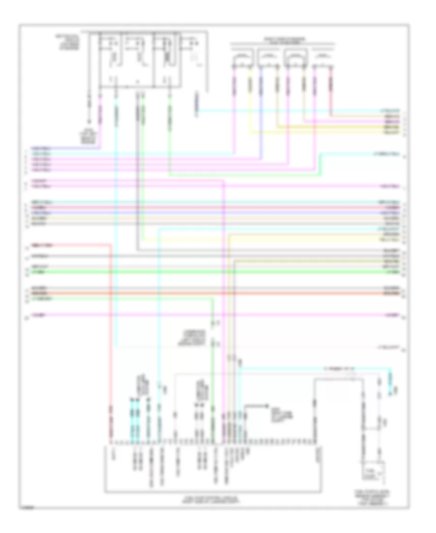
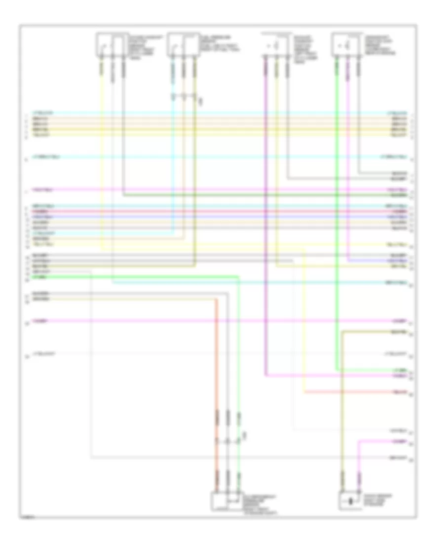
1.4L VIN 4, Hybrid System Wiring Diagram (1 of 13) for Chevrolet Volt 2011
List of elements for 1.4L VIN 4, Hybrid System Wiring Diagram (1 of 13) for Chevrolet Volt 2011:
- (engine harness, 5 cm from power steering control module breakout)
- (left side of engine compt) power inverter module
- 300v u phase
- 300v v phase
- 300v w phase
- 300v+
- 300v-
- Air conditioning system
- Automatic transmission assembly
- Batt pos volt
- Computer data lines system
- Cos +
- Cos -
- Drive motor 1 temperature sensor
- Drive motor 2
- Drive motor 2 temperature sensor
- Drive motor control module 1
- Drive motor control module 2
- Excitation +
- Excitation -
- Ground shield
- Hot at all times
- Hot w/ ignition run relay energized
- Hybrid powertrain control module 1
- J126
- J130 (engine harness on power inverter module breakout, 28.5 cm from power inverter module x3)
- Nca
- Rtn
- Serial data +
- Serial data -
- Sig
- Sin +
- Sin -
- Tpim fuse 10a
- Tpim/tcm fuse 15a
- Underhood fuse block (left side of engine compt)
1.4L VIN 4, Hybrid System Wiring Diagram (2 of 13) for Chevrolet Volt 2011
List of elements for 1.4L VIN 4, Hybrid System Wiring Diagram (2 of 13) for Chevrolet Volt 2011:
- 12v
- 12v ref
- 300v u phase
- 300v v phase
- 300v w phase
- Automatic transmission assembly
- Auxiliary transmission fluid pump
- Auxiliary transmission fluid pump control module
- Batt pos volt
- Computer data lines system
- Contactor status
- Drive motor 1
- G107
- Gnd
- Hybrid powertrain control module 1
- Ims mode sw d1 sig
- Ims mode sw d2 sig
- Ims mode sw r1 sig
- Ims mode sw r2 sig
- Ims mode sw s sig
- Logic
- Nca
- Power inverter module (left side of engine compt)
- Red
- Red b
- Run/crnk ign 1 volt
- Serial data 2
- Sig gnd
- Transmission internal mode switch
- X190
1.4L VIN 4, Hybrid System Wiring Diagram (3 of 13) for Chevrolet Volt 2011
List of elements for 1.4L VIN 4, Hybrid System Wiring Diagram (3 of 13) for Chevrolet Volt 2011:
- (diagram 5 of 13)
- 14v power module jumper connector
- 5 volt ref
- A/c compressor jumper connector
- Air conditioning system
- Anti-theft system
- Batt (-) rly ctrl
- Batt 1 (+) rly ctrl
- Batt 2 (+) rly ctrl
- Batt 3 (+) rly ctrl
- Batt 3 (-) rly ctrl
- Batt pos volt
- Bus high serial data
- Bus low serial data
- Charge port door open request switch
- Computer data lines system
- Coolant temp sens sig
- Coolant valve sens sig
- Cooling fans system
- Empty fuse 20a
- Fuel door open sig
- Fuel door release sw sig
- Fuel door status sig
- G302 (under front passenger's door sill trim)
- Ground
- High ref
- Hood open switch sig
- Hot at all times
- Hvac mode sens sig
- Hybrid battery pack coolant control valve (right rear of engine compt)
- Hybrid powertrain control module 2
- Interlock loop sig 1
- J517
- Loop sig 2
- Low press sens sig
- Low ref
- Port door sw sig
- Power inverter module assembly cable cover
- Pwm sig
- Rear body fuse block (left rear corner of luggage compt)
- Refrigerant sens sig
- Serial data (+)
- Serial data (-)
- To battery charger jumper connector (diagram 5 of 13)
- To hybrid battery pack (diagram 8 of 13)
- To hybrid battery pack b
- Trunk, tailgate, fuel doors system
- Underhood fuse block (left side of engine compt)
- Vicm fuse 10a
- X190
- X350
- X500
- X505
1.4L VIN 4, Hybrid System Wiring Diagram (4 of 13) for Chevrolet Volt 2011
List of elements for 1.4L VIN 4, Hybrid System Wiring Diagram (4 of 13) for Chevrolet Volt 2011:
- Auxiliary heater ctrl
- B+ volt
- Battery fuse block (rear of luggage compt)
- Battery state of charge indicator
- Body control module (under right side of dash)
- Ccm/vicm fuse 5a
- Charge port door position switch (behind rear of left front fender)
- Communication enable
- Computer data lines system
- Contactor status
- Control pilot sig 1
- Coolant motor enable
- Coolant mtr ctrl
- Cooling fan ctrl
- Cooling fan enable
- Cooling fan feedback sig
- Cooling fan speed sig
- Cooling fans system
- Cooling fans system air conditioning system
- Cooling fans system computer data lines system
- Fan control signal
- Fuel door lck/unlck ref
- Fuel door lck/unlck sig
- Fuse 200a
- G103 (front of left frame rail)
- G105 (front of right frame rail)
- Gmlan serial data
- Gnd
- High control
- High voltage fault sig
- Hot at all times
- Hot w/ ignition run relay energized
- Hybrid battery pack coolant pump (front of engine compt, behind radiator)
- Hybrid powertrain control module 2
- Ind ctrl
- Low reference
- Mode mtr low ctrl
- Motor feedback sig
- Mtr ctrl
- Mtr enable
- Mtr feed- back sig
- Mtr feedback signal
- Nca
- Pilot sig ind ctrl
- Port door rly ctrl
- Port door sens sig
- Port door wakeup sig
- Proximity status signal 1
- Refuel request sw sig
- Run/crank ign 1 volt
- Serial data 2
- Sol valve ctrl
- To hybrid battery pack (diagram 6 of 13)
- To hybrid battery pack (diagram 8 of 13)
- Trunk, tailgate, fuel doors system
- Underhood fuse block (left side of engine compt)
- Wakeup serial data
- X103
- X107
- X250
- X275
1.4L VIN 4, Hybrid System Wiring Diagram (5 of 13) for Chevrolet Volt 2011
List of elements for 1.4L VIN 4, Hybrid System Wiring Diagram (5 of 13) for Chevrolet Volt 2011:
- (behind rear of left front fender) charge port door actuator
- (not used)
- 14v power module (center of luggage compt)
- Batt pos volt
- Battery charger (right front corner of engine compt)
- Battery charger control module
- Battery charger jumper connector
- Charge port door relay
- Chrg dr fuse 20a
- Chrgr fuse 40a
- Communication enable
- Computer data lines system
- Coolant heater control module jumper connector
- From hybrid powertrain control module 2 (diagram 3 of 13)
- Fuse 20a
- G103 (front of left frame rail)
- G104 (front of right frame rail)
- G401
- Ground
- Hi volt batt (+)
- Hi volt batt (-)
- High serial data
- High volt batt (+)
- High volt batt (-)
- Hot at all times
- Hot w/ ignition run relay energized
- Hybrid battery charger receptacle (behind rear of left front fender)
- Hybrid battery pack (under center of vehicle)
- Hybrid battery pack high voltage manual disconnect lever (top rear of hybrid battery pack section 2)
- Hybrid/ev battery contactor assembly
- Hybrid/ev battery pack connector jumper harness
- Hybrid/ev battery pack fuse cover
- Hybrid/ev battery pack fuse insulator
- Ign 1 volt
- Low serial data
- Misc run/crnk fuse 5a
- Nca
- Ress cool pump fuse 10a
- Run/crnk ign 1 volt
- Serial data (+)
- Serial data (-)
- To hybrid battery pack (diagram 8 of 13)
- Underhood fuse block (left side of engine compt)
- Voltage ac ground
- Voltage ac line 1
- Wakeup data 2
- Wakup serial data 2
- X105
1.4L VIN 4, Hybrid System Wiring Diagram (6 of 13) for Chevrolet Volt 2011
List of elements for 1.4L VIN 4, Hybrid System Wiring Diagram (6 of 13) for Chevrolet Volt 2011:
- (diagram 4 of 13)
- (under center of vehicle) hybrid battery pack
- (under front passenger's door sill trim) g302
- Abs/ress chrgr fuse 5a
- Batt pos volt
- Battery energy control module
- Case ground
- Communication enable
- Computer data lines system
- Data communication (+)
- Data communication (-)
- From hybrid powertrain control module a
- G340
- G341
- Ground
- High voltage fault sig
- Hot at all times
- Hot w/ ignition run relay energized
- Hybrid/ev battery contactor assembly
- Hybrid/ev battery pack coolant heater
- Hybrid/ev battery pack coolant temperature sensor
- Hybrid/ev battery pack coolant temperature sensor 2
- Ign 1 volt
- Inlet temp sens (+)
- Inlet temp sens (-)
- Logic
- Outlet temp sens (+)
- Outlet temp sens (-)
- Pnk
- Red
- Ress fuse 10a
- Serial data (+)
- Serial data (-)
- Storage +
- Tan
- Underhood fuse block (left side of engine compt)
- Wakup serial data 2
1.4L VIN 4, Hybrid System Wiring Diagram (7 of 13) for Chevrolet Volt 2011
List of elements for 1.4L VIN 4, Hybrid System Wiring Diagram (7 of 13) for Chevrolet Volt 2011:
- (under center of vehicle) hybrid battery pack
- 5v ref
- Battery energy control module
- Current sens sig
- Current sens signal
- Current sens volt ref
- High 2 serial data
- High volt fault sig
- Hybrid battery interface control module 1
- Hybrid battery interface control module 2
- Hybrid battery interface control module 3
- Hybrid battery interface control module 4
- Hybrid/ev battery pack current sensor
- Low 2 serial data
- Low ref
- Nca
- Sig gnd
- To hybrid/ev battery battery module 6 (diagram 11 of 13)
- To hybrid/ev battery module 7 (diagram 12 of 13)
1.4L VIN 4, Hybrid System Wiring Diagram (8 of 13) for Chevrolet Volt 2011
List of elements for 1.4L VIN 4, Hybrid System Wiring Diagram (8 of 13) for Chevrolet Volt 2011:
- 300v+
- Battery charging system positive contactor
- Battery energy control module
- From 14v power module (diagram 5 of 13)
- From battery charger (diagram 5 of 13)
- From hybrid powertrain control module (diagram 3 of 13)
- From hybrid powertrain control module (diagram 4 of 13)
- Fuse 20a
- G302 (under front passenger's door sill trim)
- Hybrid/ev battery contactor assembly
- Hybrid/ev battery coolant heater transistor
- Hybrid/ev battery multifunction contactor
- Hybrid/ev battery pack
- Hybrid/ev battery pack coolant heater
- Hybrid/ev battery pack fuse insulator
- Hybrid/ev battery positive contactor
- Hybrid/ev battery precharge resistor
- Hybrid/ev battery precharge transistor
- Logic
- Nca
- Pnk
- Pos status
- Power inverter module (left side of engine compt)
- Red
- To hybrid/ev battery module (diagram 9 of 13)
- To hybrid/ev battery module 9 (diagram 13 of 13)
1.4L VIN 4, Hybrid System Wiring Diagram (9 of 13) for Chevrolet Volt 2011
List of elements for 1.4L VIN 4, Hybrid System Wiring Diagram (9 of 13) for Chevrolet Volt 2011:
- Batt vol sig 1
- Batt vol sig 10
- Batt vol sig 11
- Batt vol sig 12
- Batt vol sig 13
- Batt vol sig 14
- Batt vol sig 15
- Batt vol sig 16
- Batt vol sig 17
- Batt vol sig 18
- Batt vol sig 2
- Batt vol sig 3
- Batt vol sig 4
- Batt vol sig 5
- Batt vol sig 6
- Batt vol sig 7
- Batt vol sig 8
- Batt vol sig 9
- Hybrid battery pack section 3 (rear section of hybrid battery assembly)
- Hybrid/ev battery interface control module 4
- Hybrid/ev battery module 1
- Hybrid/ev battery module 2
- Hybrid/ev battery temperature sensor 1
- Hybrid/ev battery temperature sensor 2
- Hybrid/ev battery temperature sensor 3
- Low ref
- Nca
- Temp sig 1
- Temp sig 2
- Temp sig 3
- To hybrid/ev battery module 3 (diagram 10 of 13)
1.4L VIN 4, Hybrid System Wiring Diagram (10 of 13) for Chevrolet Volt 2011
List of elements for 1.4L VIN 4, Hybrid System Wiring Diagram (10 of 13) for Chevrolet Volt 2011:
- Batt vol sig 1
- Batt vol sig 10
- Batt vol sig 11
- Batt vol sig 12
- Batt vol sig 2
- Batt vol sig 3
- Batt vol sig 4
- Batt vol sig 5
- Batt vol sig 6
- Batt vol sig 7
- Batt vol sig 8
- Batt vol sig 9
- From hybrid/ev battery module 2 (diagram 9 of 13)
- Hybrid battery pack section 3 (rear section of hybrid battery assembly)
- Hybrid/ev battery interface control module 3
- Hybrid/ev battery module 3
- Hybrid/ev battery module 4
- Hybrid/ev battery temperature sensor 4
- Hybrid/ev battery temperature sensor 5
- Hybrid/ev battery temperature sensor 6
- Hybrid/ev battery temperature sensor 7
- Low ref
- Nca
- Temp sig 4
- Temp sig 5
- Temp sig 6
- Temp sig 7
- To hybrid battery pack section 2 (diagram 11 of 13)
1.4L VIN 4, Hybrid System Wiring Diagram (11 of 13) for Chevrolet Volt 2011
List of elements for 1.4L VIN 4, Hybrid System Wiring Diagram (11 of 13) for Chevrolet Volt 2011:
- (middle section of hybrid battery assembly) hybrid battery pack section 2
- Batt vol sig 1
- Batt vol sig 10
- Batt vol sig 11
- Batt vol sig 12
- Batt vol sig 2
- Batt vol sig 3
- Batt vol sig 4
- Batt vol sig 5
- Batt vol sig 6
- Batt vol sig 7
- Batt vol sig 8
- Batt vol sig 9
- From hybrid/ev battery module 4 (diagram 10 of 13)
- From hybrid/ev battery pack current sensor (diagram 7 of 13)
- Fuse 350a
- Hybrid battery pack high voltage manual disconnect lever (top rear of hybrid battery pack section 2)
- Hybrid/ev battery interface control module 2
- Hybrid/ev battery module 5
- Hybrid/ev battery module 6
- Hybrid/ev battery temperature sensor 10
- Hybrid/ev battery temperature sensor 11
- Hybrid/ev battery temperature sensor 8
- Hybrid/ev battery temperature sensor 9
- Low ref
- Nca
- Temp sig 10
- Temp sig 11
- Temp sig 8
- Temp sig 9
1.4L VIN 4, Hybrid System Wiring Diagram (12 of 13) for Chevrolet Volt 2011
List of elements for 1.4L VIN 4, Hybrid System Wiring Diagram (12 of 13) for Chevrolet Volt 2011:
- Batt vol sig 1
- Batt vol sig 10
- Batt vol sig 11
- Batt vol sig 12
- Batt vol sig 2
- Batt vol sig 3
- Batt vol sig 4
- Batt vol sig 5
- Batt vol sig 6
- Batt vol sig 7
- Batt vol sig 8
- Batt vol sig 9
- From hybrid/ev battery pack current sensor (diagram 7 of 13)
- Hybrid battery pack section 1 (front section of hybrid battery assembly)
- Hybrid/ev battery interface control module 1
- Hybrid/ev battery module 7
- Hybrid/ev battery module 8
- Hybrid/ev battery temperature sensor 12
- Hybrid/ev battery temperature sensor 13
- Hybrid/ev battery temperature sensor 14
- Hybrid/ev battery temperature sensor 15
- Low ref
- Nca
- Temp sig 12
- Temp sig 13
- Temp sig 14
- Temp sig 15
- To hybrd/ev battery module 9 (diagram 13 of 13)
1.4L VIN 4, Hybrid System Wiring Diagram (13 of 13) for Chevrolet Volt 2011
List of elements for 1.4L VIN 4, Hybrid System Wiring Diagram (13 of 13) for Chevrolet Volt 2011:
- Batt vol sig 12
- Batt vol sig 13
- Batt vol sig 14
- Batt vol sig 15
- Batt vol sig 16
- Batt vol sig 17
- Batt vol sig 18
- From hybrid/ev battery module 8 (diagram 12 of 13)
- From hybrid/ev battery positive contactor (diagram 8 of 13)
- Hybrid battery pack section 1 (front section of hybrid battery assembly)
- Hybrid/ev battery interface control module 1
- Hybrid/ev battery module 9
- Hybrid/ev battery temperature sensor 16
- Low ref
- Nca
- Temp sig 16
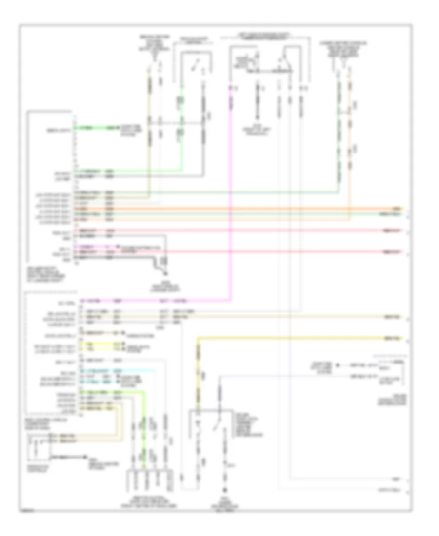
EXTERIOR LIGHTS
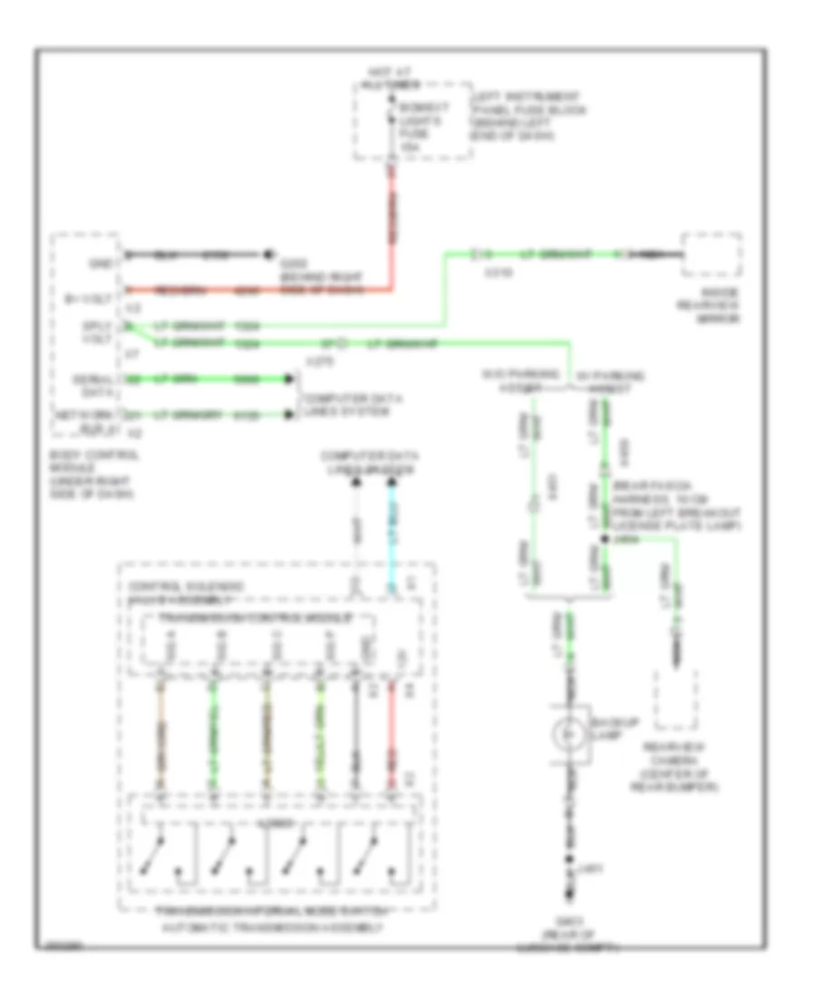
Backup Lamps Wiring Diagram for Chevrolet Volt 2011
List of elements for Backup Lamps Wiring Diagram for Chevrolet Volt 2011:
- 12v
- Automatic transmission assembly
- B+ volt
- Backup lamp
- Bcm/ext lights fuse 15a
- Body control module (under right side of dash)
- Bus 4
- Computer data lines system
- Control solenoid valve assembly
- Data
- G202 (behind right side of dash)
- G403 (rear of luggage compt)
- Gnd
- Hot at all times
- Inside rearview mirror
- Left instrument panel fuse block (behind left end of dash)
- Logic
- Nca
- Network
- Rearview camera (center of rear bumper)
- Red
- Serial
- Sig a
- Sig b
- Sig c
- Sig p
- Sply
- Transmission control module
- Transmission internal mode switch
- Volt
- W/ parking assist
- W/o parking assist
- X275
- X310
- X450
- X451
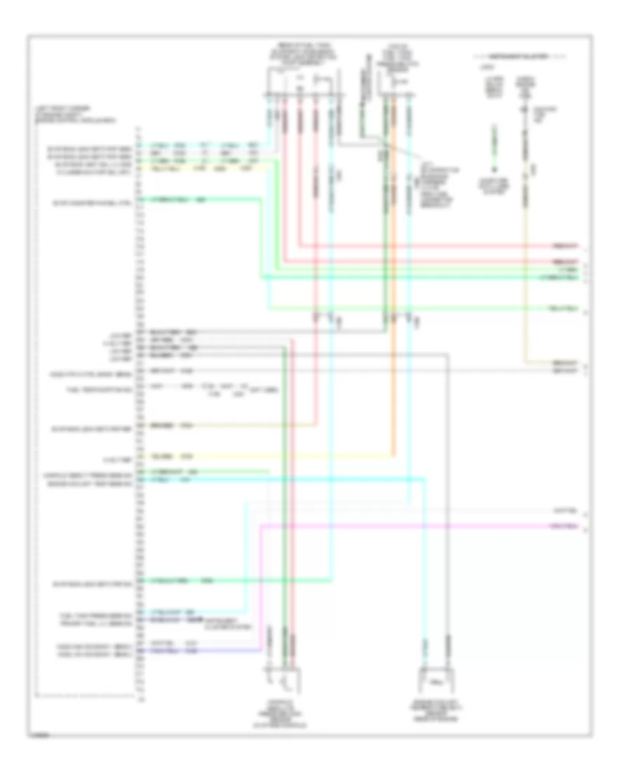
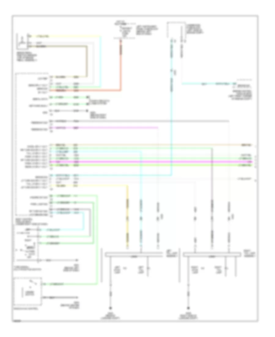
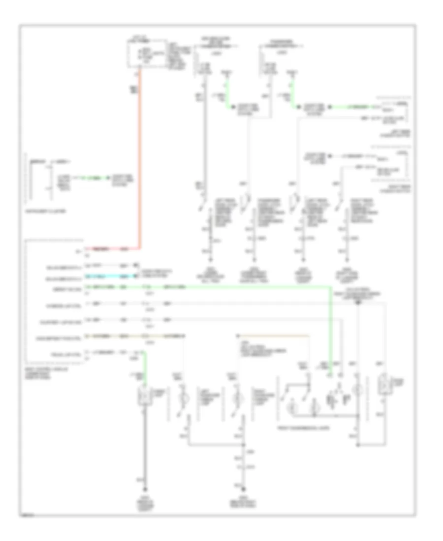
Exterior Lamps Wiring Diagram (1 of 2) for Chevrolet Volt 2011
List of elements for Exterior Lamps Wiring Diagram (1 of 2) for Chevrolet Volt 2011:
- Auto
- B+ volt
- Bcm/ext lights fuse 15a
- Body control module (bcm) (under right side of dash)
- Brake pedal position sensor (top of brake pedal assembly)
- Brake sig
- Brake sig x1
- Chmsl sply volt
- Computer data lines system
- Engine control module (ecm) (left front corner of engine compt)
- Feedback sig
- G201 (behind left side of dash)
- G202 (behind right side of dash)
- G204 (behind center of dash)
- G403 (rear of luggage compt)
- G405 (right side of luggage compt)
- Gnd
- Hazard sw sig
- Hazard switch
- Head
- Hot at all times
- Left
- Left instrument panel fuse block (behind left end of dash)
- Left stop lamp
- Left tail lamp
- Left tail lamp assembly
- Lf turn sig sply volt
- Lf turn sw sig
- Logic
- Low ref
- Lr turn sig sply volt
- Network bus 4
- Off
- Park
- Park lamp sig
- Park lp sply volt
- Radio/hvac control
- Rear lp sply volt
- Rf turn sig sply volt
- Rf turn sw sig
- Right
- Right stop lamp
- Right tail lamp
- Right tail lamp assembly
- Rr turn sig sply volt
- Sens sig
- Sens sply volt
- Serial data
- Tail lp sply volt
- Turn signal/ multi-function switch
- Underhood fuse block (left side of engine compt)
- X225
- X275
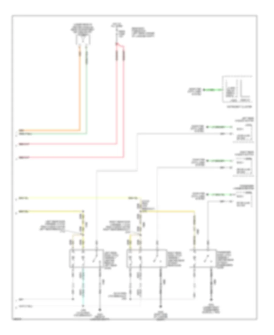
Exterior Lamps Wiring Diagram (2 of 2) for Chevrolet Volt 2011
List of elements for Exterior Lamps Wiring Diagram (2 of 2) for Chevrolet Volt 2011:
- Center high mounted stop lamp
- Computer data lines system
- Display
- Driver outside rear view mirror
- G101 (front of left frame rail)
- G204 (behind center of dash)
- G301 (under driver's door sill trim)
- G302 (under front passenger's door sill trim)
- G403 (rear of luggage compt)
- Gnd
- Hot w/ ignition run relay energized
- Instrument cluster
- J102
- J451
- J453 (rear fascia harness, 9 cm from rear object sensor - left middle connector breakout)
- J515
- J615
- J902
- Left license plate lamp
- Left park/ turn signal lamp
- Left turn signal repeater lamp
- Logic
- Misc run/crnk fuse 5a
- Nca
- Passenger outside rear view mirror
- Power distribution system
- Right license plate lamp
- Right park/ turn signal lamp
- Right turn signal repeater lamp
- Serial data
- Underhood fuse block (left side of engine compt)
- W/ parking assist
- W/o parking assist
- X100
- X101
- X107
- X225
- X275
- X450
- X451
- X500
- X510
- X600
- X610
- X900
- X905
GROUND DISTRIBUTION
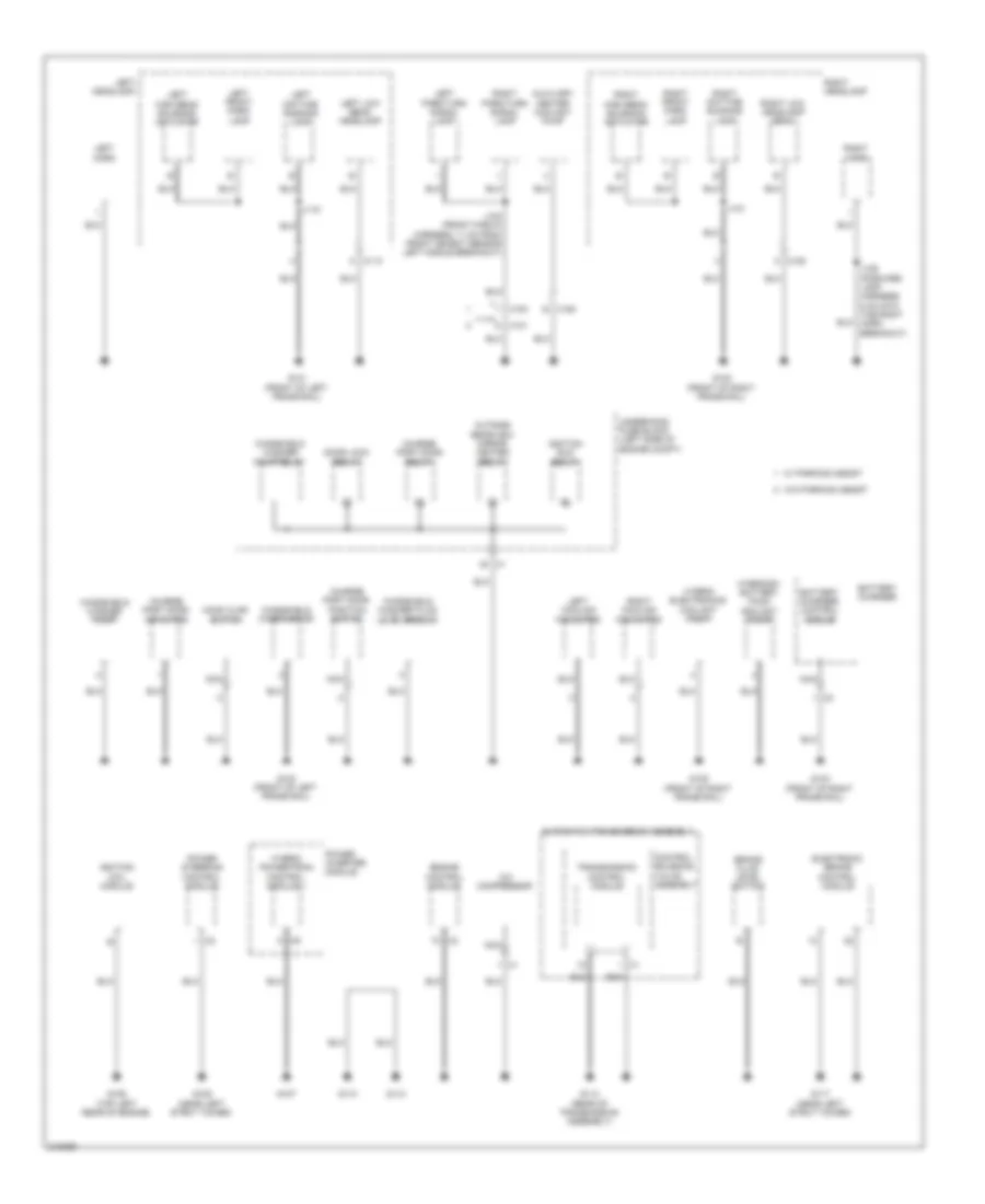
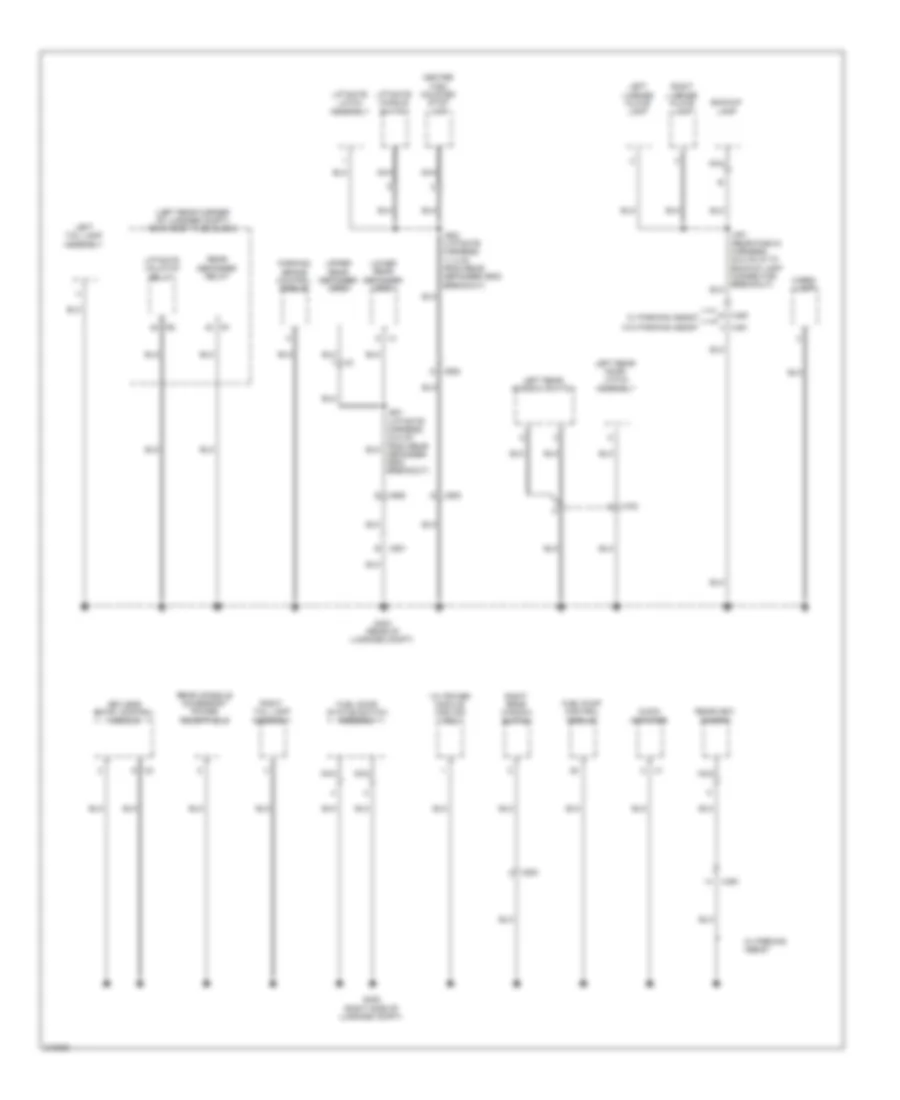
Ground Distribution Wiring Diagram (1 of 4) for Chevrolet Volt 2011
List of elements for Ground Distribution Wiring Diagram (1 of 4) for Chevrolet Volt 2011:
- A/c compressor
- Automatic transmission assembly
- Auxiliary heater coolant pump
- Battery charger
- Battery charger control module
- Brake fluid level switch
- Charge port door actuator
- Charge port door position switch
- Charge port door relay
- Control solenoid valve assembly
- Door lock relay
- Electronic brake control module
- Engine control module
- G101 (front of left frame rail)
- G102 (front of right frame rail)
- G103 (front of left frame rail)
- G104 (front of right frame rail)
- G105 (front of right frame rail)
- G106 (top left rear of engine)
- G107
- G109 (near left strut tower)
- G110
- G112
- G113 (rear of transmission assembly)
- G117 (near left strut tower)
- Hood ajar switch
- Hybrid electronics coolant pump
- Hybrid powertrain control module 1
- Hybrid/ev battery pack coolant pump
- Ignition coil module
- Ignition run relay
- J102 (front fascia harness, 11 cm from front object sensor left middle breakout)
- J106 (forward lamp harness, 5 cm into the right horn breakout)
- J115
- J121
- Left cooling fan motor
- Left daytime running lamp
- Left front park lamp
- Left headlamp
- Left high beam solenoid actuator
- Left horn
- Left low beam headlamp
- Left park/turn signal lamp
- Nca
- Outside rearview mirror heater relay
- Power inverter module
- Power steering control module
- Right cooling fan motor
- Right daytime running lamp
- Right front park lamp
- Right headlamp
- Right high beam solenoid actuator
- Right horn
- Right low headlamp beam
- Right park/turn signal lamp
- Transmission control module
- Underhood fuse block (left side of engine compt)
- W/ parking assist
- W/o parking assist
- Windshield washer fluid level sensor
- Windshield washer pump
- Windshield washer pump relay
- Windshield wiper motor
- X100
- X101
- X110
- X120
- X180 e
- X9 a
Ground Distribution Wiring Diagram (2 of 4) for Chevrolet Volt 2011
List of elements for Ground Distribution Wiring Diagram (2 of 4) for Chevrolet Volt 2011:
- (not used)
- 14v power module
- Auxiliary data connector
- Battery
- Battery energy control module
- Blower motor control module
- Body control module
- Center console accessory power receptacle
- Cigarette lighter receptacle
- Data link connector
- Dome lamp
- Driver information center switch
- Front dome/ reading lamps
- G201 (behind left side of dash)
- G202 (behind right side of dash)
- G203 (behind left side of dash)
- G204 (behind center of dash)
- G205 (left side of instrument panel)
- G304 (front of center console)
- G340
- G341
- G401
- G404
- Garage door opener
- Horn switch
- Hvac control module
- Hybrid/ev battery pack
- Inflatable restraint sensing & diagnostic module
- Info display module
- Inside rearview mirror
- Instrument cluster
- J315
- J340
- J350 (headliner harness, 5 cm from breakout for overhead console connectors)
- J353 (headliner harness, 35.4 cm from right sunshade mirror lamp breakout)
- Left instrument panel fuse block (behind left end of dash)
- Left steering wheel control switch
- Left sunshade mirror lamp
- Overhead console multifunction switch
- Park brake control switch
- Park position switch
- Passenger air bag disable indicator
- Radio/ hvac controls
- Retained accessory power relay
- Right steering wheel control switch
- Right sunshade mirror lamp
- Sport mode switch
- Steering wheel air beg coil
- Steering wheel angle sensor
- Telematics button assembly
- Transmission shift lever
- Transmission shift lock control solenoid actuator
- Turn signal/ multi-function switch
- Vehicle on/off switch
- W/ parking assist
- X275
- X310
- X315 g
- X84b
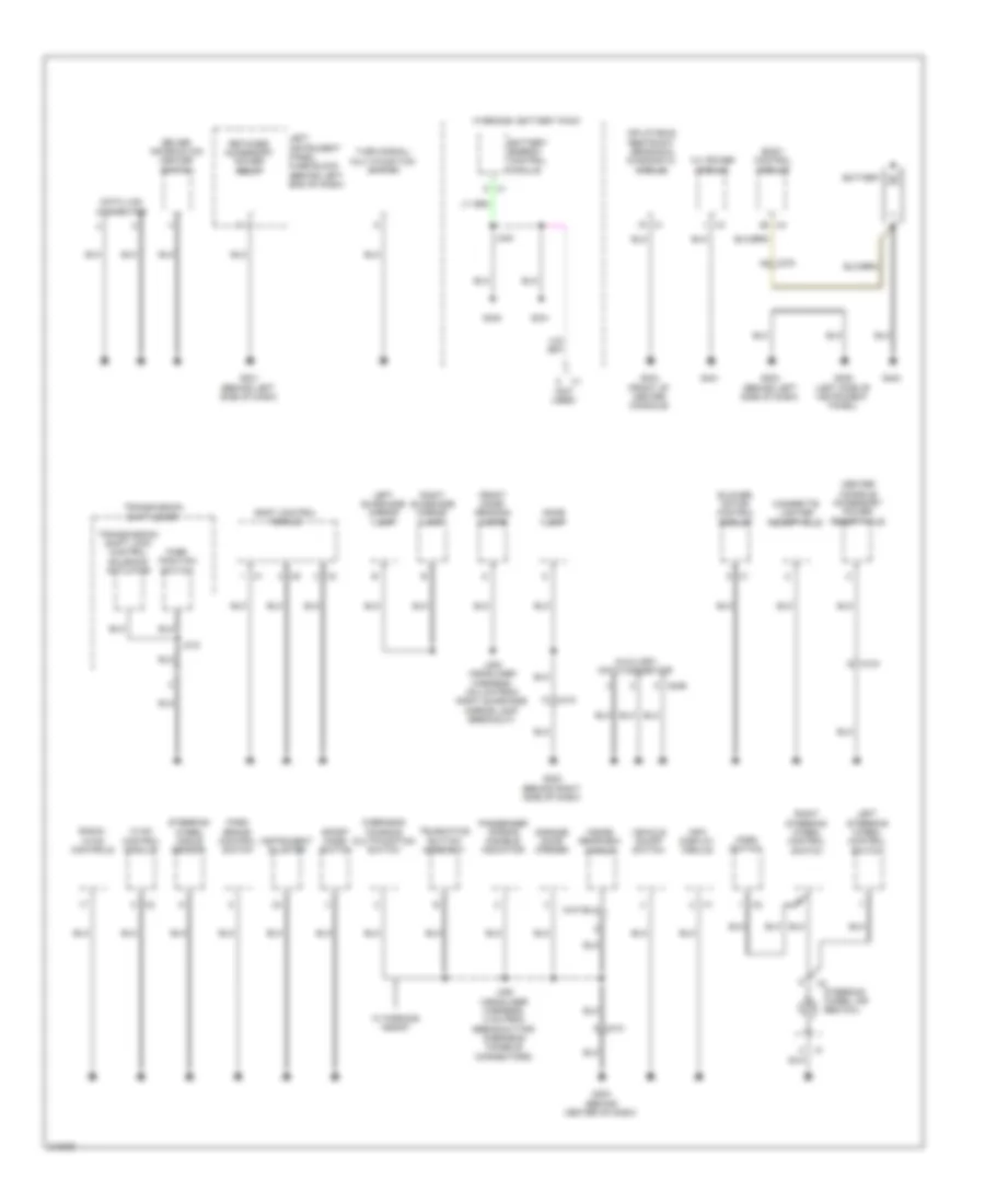
Ground Distribution Wiring Diagram (3 of 4) for Chevrolet Volt 2011
List of elements for Ground Distribution Wiring Diagram (3 of 4) for Chevrolet Volt 2011:
- (not used)
- A x1
- Battery energy control module
- Charge port door open request switch
- Coolant heater control module
- D x510
- Driver door latch assembly
- Driver outside rearview mirror
- Driver outside rearview mirror glass
- Driver window motor
- Driver window switch
- From x510 breakout) j515
- Front & rear parking assist control module
- G301 (under driver's door sill trim)
- G302 (under front passenger's door sill trim)
- G406 (right side of luggage compt)
- Horn relay
- Hybrid powertrain control module 2
- Hybrid/ev battery contactor assembly
- Hybrid/ev battery pack
- J x351
- J514 (left door harness, 8.3 cm from x510 breakout)
- J518 (left door trim harness, 16.3 cm from x505 breakout)
- Left turn signal repeater lamp
- Multi-axis acceleration sensor
- Nca
- Outside rearview mirror switch
- Passenger compartment heater coolant control valve
- Passenger door latch assembly
- Passenger outside rearview mirror
- Passenger outside rearview mirror glass
- Passenger presence detection module
- Passenger window switch
- Radio
- Rear body fuse block (left rear corner of luggage compt)
- Refuel request switch
- Right rear door latch assembly
- Right turn signal repeater lamp
- Seat heating control module
- Telematics communication interface control module
- W/ front seat heater
- W/ parking assist
- X275
- X320
- X325
- X500
- X505
- X600
- X610 e
- X800
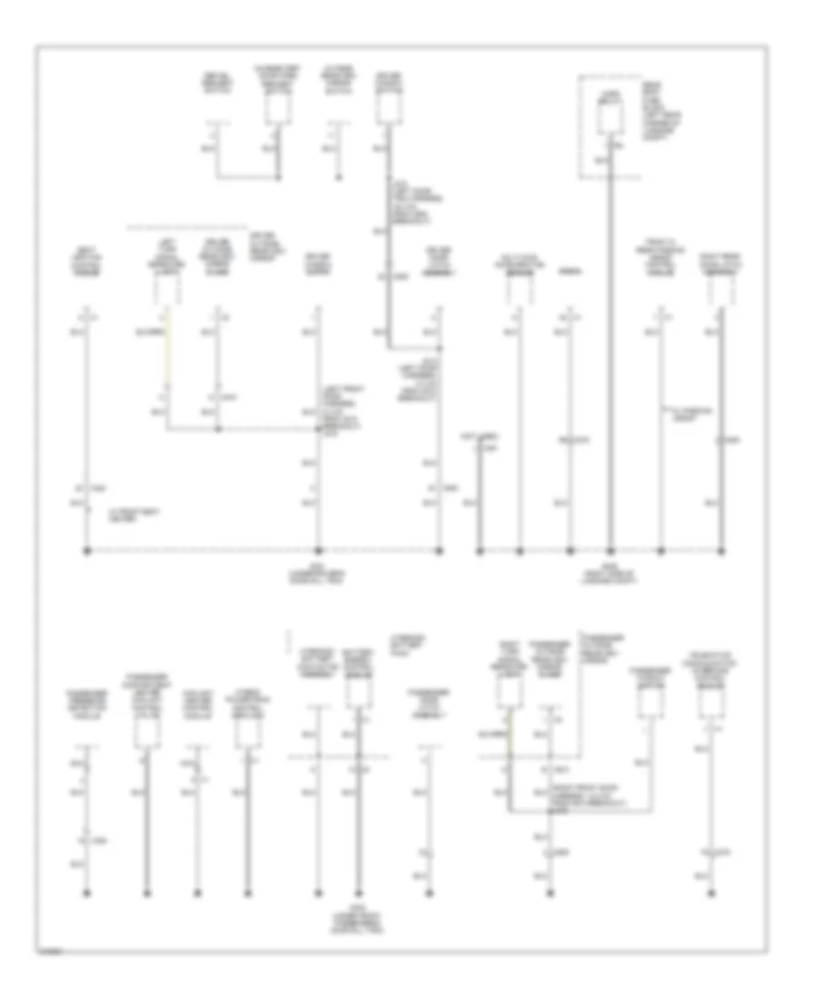
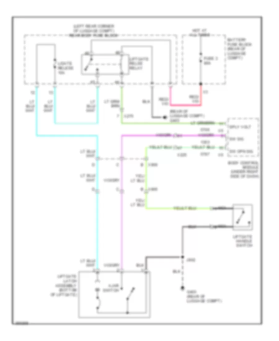
Ground Distribution Wiring Diagram (4 of 4) for Chevrolet Volt 2011
List of elements for Ground Distribution Wiring Diagram (4 of 4) for Chevrolet Volt 2011:
- (left rear corner of luggage compt) rear body fuse block
- 14v power module cooling fan
- A x1
- Audio amplifier
- B x906
- Backup lamp
- Cargo lamp
- Center high mounted stop lamp
- Fuel door status switch assembly
- Fuel pump control module
- G x900
- G x905
- G403 (rear of luggage compt)
- G405 (right side of luggage compt)
- J902 (liftgate harness, 11.4 cm from rear defogger grid breakout)
- Keyless entry control module
- Left license plate lamp
- Left rear door latch assembly
- Left rear window switch
- Left tail lamp assembly
- Liftgate handle switch
- Liftgate latch assembly
- Liftgate unlatch relay
- Lower rear defogger grid
- Nca
- Parking brake control module
- Rear console accessory power receptacle
- Rear defogger relay
- Rearview camera
- Right license plate lamp
- Right rear window switch
- Right tail lamp assembly
- Upper rear defogger grid
- W/ parking assist
- W/o parking assist
- X450
- X451
- X700
- X800
- X901
HEADLIGHTS
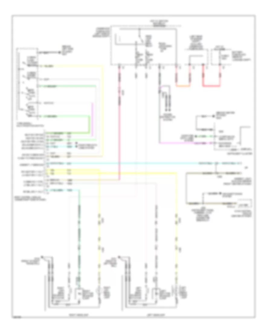
Headlights Wiring Diagram for Chevrolet Volt 2011
List of elements for Headlights Wiring Diagram for Chevrolet Volt 2011:
- (behind center of dash) g204
- (behind left side of dash) g201
- (left rear of engine compt) auxiliary underhood fuse block
- Air conditioning system
- Ambient light/ sunload sensor (front center of dash)
- Ambient lt sens sig
- Auto
- Battery fuse block (rear of luggage compt)
- Body control module (under right side of dash)
- Computer data lines system
- Dim sw hi beam sig
- Display
- Flash to pass sig sw
- Fuse 5 150a
- G101 (front of left frame rail)
- G102 (front of right frame rail)
- Gmlan ser data (+)
- Gmlan ser data (-)
- Gnd
- Hdlp sw off sig
- Hdlp sw on sig
- Hdlp sw prk lp sig
- Head
- Head lamp high beam relay
- Hi beam dimmer switch
- Hi beam flash to pass switch
- Hi beam lt fuse 5a
- Hi beam rly ctrl
- Hi beam rt fuse 5a
- Hot at all times
- Hot w/ ignition run relay energized
- Hvac control module (center of dash)
- Instrument cluster
- J115
- J121
- J220 (instrument panel harness, 10 cm from x260 connector breakout)
- Left daytime running lamp
- Left headlamp
- Left high beam solenoid actuator
- Left low beam head- lamp
- Lf drl sply volt
- Lh hdlp sply volt
- Lo spd gmlan serial data
- Logic
- Low ref
- Misc run/crnk fuse 5a
- Off
- Park
- Power distribution system
- Red
- Rf drl sply volt
- Rh hdlp sply volt
- Right daytime running lamp
- Right headlamp
- Right high beam solenoid actuator
- Right low beam head- lamp
- Run/crank ign 1 volt
- Turn signal/ multi-function switch
- Underhood fuse block (left side of engine compt)
- X107
- X225
- X250
- X275
HORN
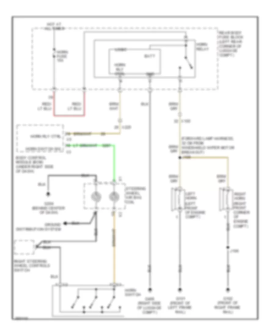
Horn Wiring Diagram for Chevrolet Volt 2011
List of elements for Horn Wiring Diagram for Chevrolet Volt 2011:
- (left front of engine compt)
- (right front corner of
- Batt
- Body control module (bcm) (under right side of dash)
- Compt)
- Engine
- G101 (front of left frame rail)
- G102 (front of right frame rail)
- G204 (behind center of dash)
- G406 (right side of luggage compt)
- Gnd
- Ground distribution system
- Horn fuse 15a
- Horn relay
- Horn rly ctrl
- Horn switch
- Horn switch sig
- Hot at all times
- J105
- J106
- Left horn
- Logic
- Rear body fuse block (left rear corner of luggage compt)
- Right horn
- Right steering wheel controls switch
- Steering wheel air bag coil
- X105
- X225
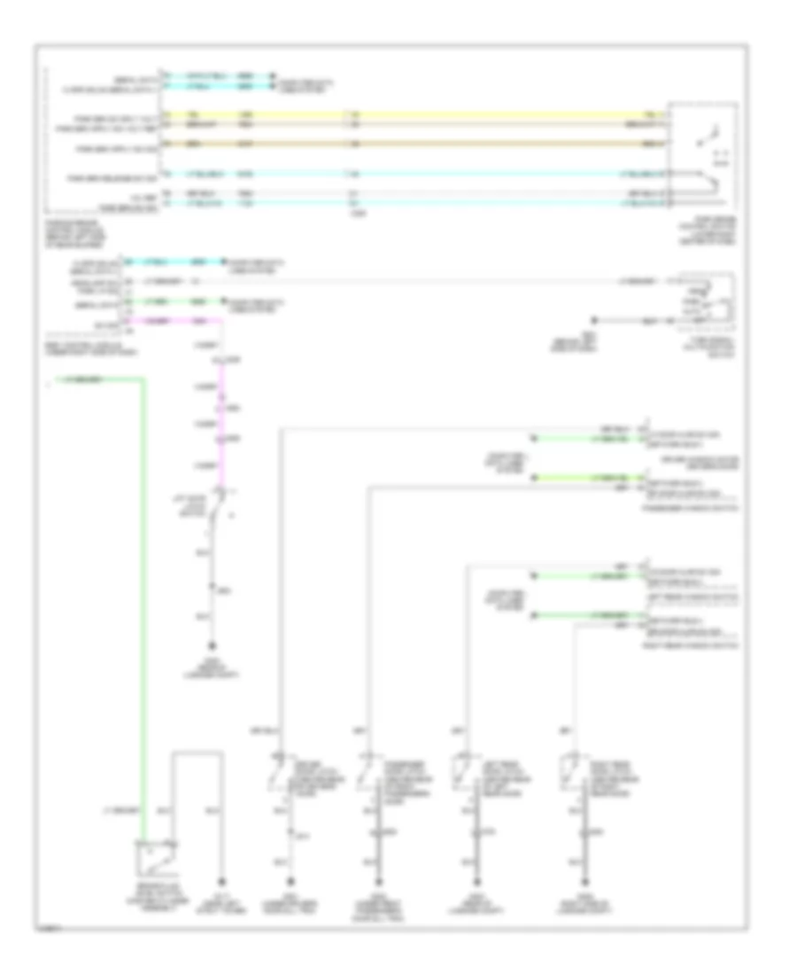
INSTRUMENT CLUSTER
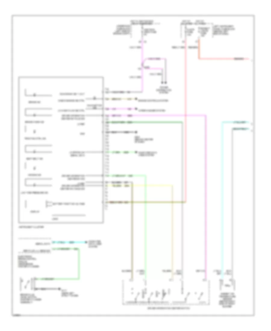
Instrument Cluster Wiring Diagram (1 of 2) for Chevrolet Volt 2011
List of elements for Instrument Cluster Wiring Diagram (1 of 2) for Chevrolet Volt 2011:
- Air bag ind
- Ambient air temperature sensor (behind right side of front bumper)
- Back
- Battery positive voltage
- Bcn/ext lights fuse 15a
- Brake fluid level switch (master cylinder assembly)
- Brake ind
- Brake warn ind
- Brk fluid lvl sens sig
- Center sw minus sig
- Center sw plus sig
- Center sw sig
- Check engine ind ctrl
- Clstr fuse 10a
- Computer data lines system
- Config
- Display
- Driver information
- Driver information center switch
- Electronic brake control module (near brake master cylinder)
- Engine controls system
- G117 (near left strut tower)
- G204 (behind center of dash)
- Gnd
- Hot at all times
- Hot w/ ignition run relay energized
- Instrument cluster
- Left instrument panel fuse block (behind left end of dash)
- Lo ref
- Lo ref driver information
- Lo spd gmlan
- Lo wash fluid ind ctrl
- Logic
- Low tire pressure ind
- Malfunction ind
- Misc run/ crnk fuse 5a
- Power distribution system
- Run/crank ign 1 volt
- Seat belt ind
- Select
- Serial data
- Traction ctrl ind
- Underhood fuse block (left side of engine compt)
- Wiper/washer system
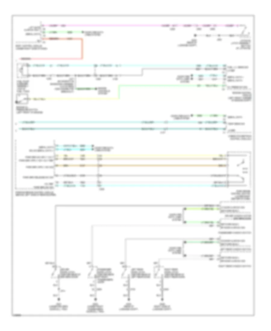
- X225
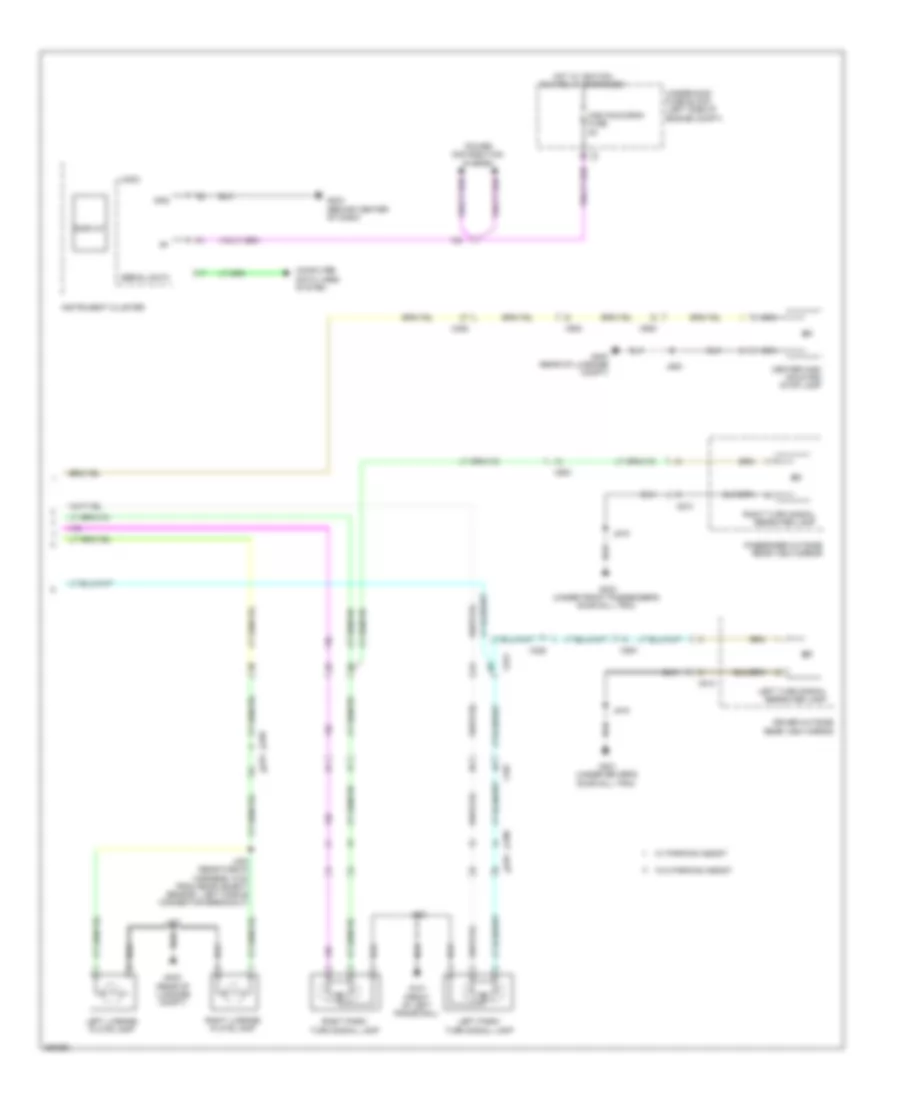
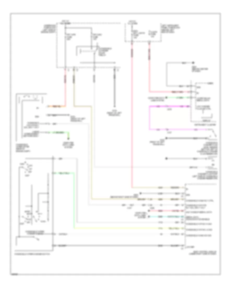
Instrument Cluster Wiring Diagram (2 of 2) for Chevrolet Volt 2011
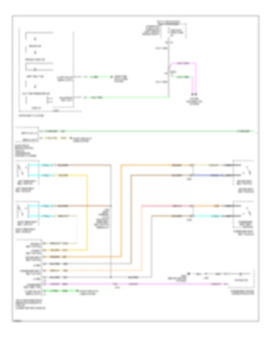
List of elements for Instrument Cluster Wiring Diagram (2 of 2) for Chevrolet Volt 2011:
- Body control module (under right side of dash)
- Computer data lines system
- Driver door latch (center rear of driver's door)
- Driver window motor (driver's door)
- Engine control module (left front corner of engine compt)
- Engine controls system
- Engine oil pressure switch (left front of engine)
- Fuel lvl sens sig
- Fuel pump & sender assembly (top of fuel tank)
- G301 (under driver's door sill trim)
- G302 (under front passenger's door sill trim)
- G403 (rear of luggage compt)
- G406 (right side of luggage compt)
- Gmlan serial data +
- Hybrid powertrain control module 2
- J377 (evaporative emissions harness, 13.5 cm from x355 connector breakout)
- J514
- J902
- Left rear door latch (center rear of left rear door)
- Left rear window switch
- Lf door ajar sw sig
- Lift gate ajar sw sig 1
- Liftgate latch assembly (bottom of liftgate)
- Lo ref
- Lr door ajar sw sig
- Network bus 3
- Network bus 4
- Oil press sw sig
- Park brake control switch (lower right center of dash)
- Park brk release sw sig
- Park brk sw sig
- Park brk sw sply volt
- Parking brake control module (behind left side of rear bumper)
- Passenger door latch (center rear of front passenger's door)
- Passenger window switch
- Rf door ajar sw sig
- Right rear door latch (center rear of right rear door)
- Right rear window switch
- Rr door ajar sw sig
- Serial data
- Serial data +
- Serial data -
- Temp sens sig
- Vol ref
- X107
- X190
- X225
- X350
- X354
- X600
- X700
- X800
- X900
- X905
INTERIOR LIGHTS
Courtesy Lamps Wiring Diagram for Chevrolet Volt 2011
List of elements for Courtesy Lamps Wiring Diagram for Chevrolet Volt 2011:
- (16.2 cm from right sunshade mirror lamp breakout) j352
- (driver's door) driver window motor
- B +
- Bcm/ ext lights fuse 15a
- Body control module (under right side of dash)
- Bus 3
- Bus 4
- Cargo lamp
- Computer data lines system
- Courtesy lmp sw sig
- Defeat dome
- Defeat sw sig
- Display
- Dome lamp
- Dome on
- Front dome/reading lamps
- G202 (behind right side of dash)
- G301 (under driver's door sill trim)
- G302 (under front passenger's door sill trim)
- G403 (rear of luggage compt)
- G406 (right side of luggage compt)
- Gmlan ser data (+)
- Gmlan ser data (-)
- Hot at all times
- Inadvertent pwr ctrl
- Instrument cluster
- Interior lmp ctrl
- J353
- J354 (45.4 cm from right sunshade mirror lamp breakout)
- J514
- Left instrument panel fuse block (behind left end of dash)
- Left rear door latch assembly (center rear of driver's door)
- Left rear door latch assembly (center rear of left rear door)
- Left rear window switch
- Left sunshade mirror lamp
- Lf dr ajar sw sig
- Lo spd gmlan serial data
- Logic
- Lr dr ajar sw sig
- Off
- Passenger door latch assembly (center rear of front passenger's door)
- Passenger window switch
- Rf dr ajar sw sig
- Right rear door latch assembly (center rear of right rear door)
- Right rear window switch
- Right sunshade mirror lamp
- Rr dr ajar sw sig
- Trunk lmp ctrl
- X225
- X310
- X311
- X600
- X700
- X800
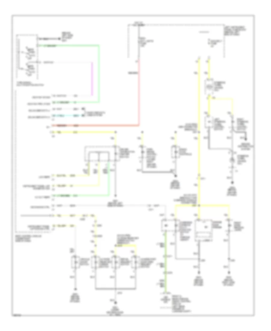
Instrument Illumination Wiring Diagram for Chevrolet Volt 2011
List of elements for Instrument Illumination Wiring Diagram for Chevrolet Volt 2011:
- (5 cm from x260 connector breakout) j221
- (6.3 cm into breakout for overhead console connectors) j351
- (6.5 cm from outside rearview mirror switch breakout) j519
- (behind left side of dash) g201
- 12 volt refr
- Auto
- B +
- Bcm/ ext lights fuse 15a
- Body control module (under right side of dash)
- Charge port door open request switch
- Computer data lines system
- Driver information center switch
- Front & rear parking assist control module (left rear corner of luggage compt)
- Front dome/ reading lamps
- G201 (behind left side of dash)
- G202 (behind right side of dash)
- G204 (behind center of dash)
- G301 (under driver's door sill trim)
- Garage door opener
- Gmlan ser data (+)
- Gmlan ser data (-)
- Ground distribution system
- Hdlp sw on sig
- Hdlp sw prk lp sig
- Head
- Hot at all times
- Ind dimming ctrl
- Instrument panel lmp dimmer sw sig x2
- Instrument panel lmp dimming ctrl x7
- J350
- J353
- J518
- Led disable sig
- Left instrument panel fuse block (behind left end of dash)
- Left steering wheel control switch
- Logic
- Low refr
- Off
- Outside rearview mirror switch
- Overhead console multi- function switch (w/ parking assist)
- Park
- Park brake control switch (lower right center of dash)
- Radio/ hvac controls
- Refuel request switch
- Right steering wheel control switch
- Steering wheel air bag coil
- Swc bklt fuse 2a
- Turn signal/ multi-function switch
- Vehicle on/off switch
- X225
- X275
- X311
- X500
- X505
NAVIGATION
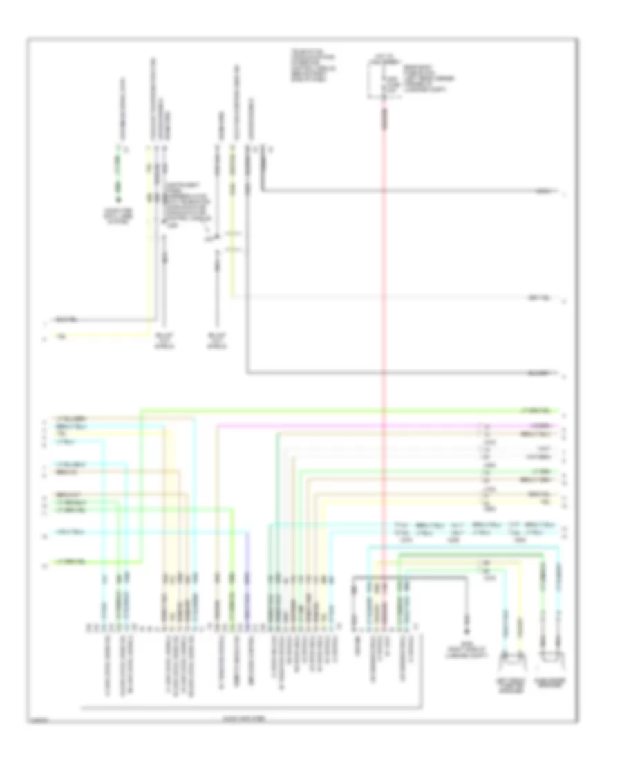
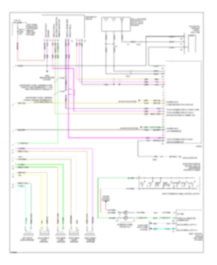
Navigation Wiring Diagram (1 of 3) for Chevrolet Volt 2011
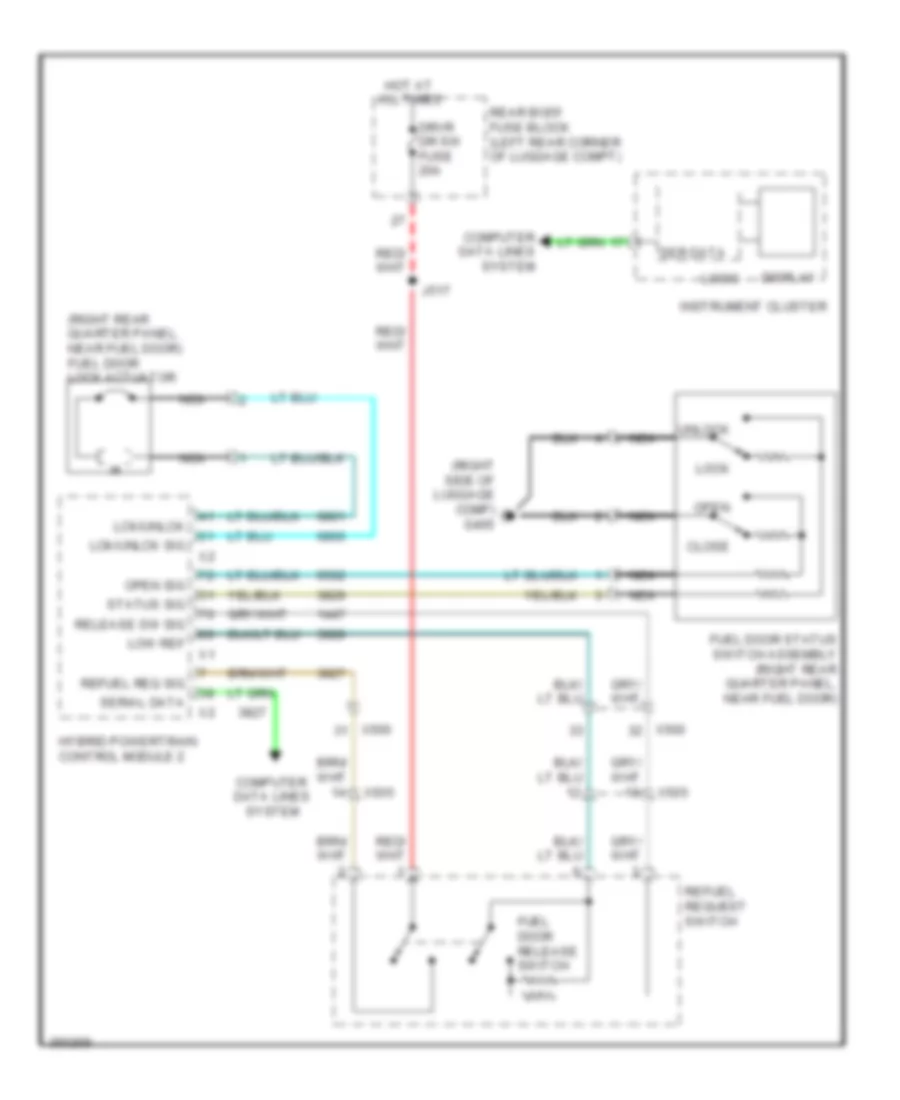
List of elements for Navigation Wiring Diagram (1 of 3) for Chevrolet Volt 2011:
- (body harness, 25 cm from g302 breakout)
- (body harness, 28 cm from x700 breakout)
- (floor console harness, 5 cm from x315)
- (instrument panel harness, in transmission shift lever breakout, 4.5 cm from x315)
- (instrument panel harness, in x275 connector breakout, 18.3 cm from x275,) j226
- (instrument panel harness, in x275 connector breakout, 7.5 cm from x275)
- (instrument panel harness, radio connector breakout, 10 cm from radio x4.) j206
- (instrument panel harness,2.5 cm from radio x1)
- (instrumental pannel harness, 5 cm from park brake control switch connector breakout)
- Aux audio common sig
- Aux audio common signal
- Aux audio screen 2
- Aux detection sig
- Auxiliary audio input
- Battery+ volt
- Center stack reset sig
- Center stack wake up sig
- Computer data lines system
- Detection sig aux
- Entertainment remote enable sig
- Front low level audio(-)
- G406 (right side of luggage compt)
- Ground
- Hot at all times
- J204
- J209
- J210 (instrumental panel harness, 6 cm from radio x1)
- J211
- J224
- J306
- J307
- J317
- Left aux audio sig 2 x1
- Left aux audio signal 2
- Left instrument panel fuse block (behind left end of dash)
- Lf audio drain wire
- Lf low level audio sig
- Lf low level audio(-)
- Lo spd gmlan serial data
- Logic
- Low reference
- Lr audio drain wire
- Lr low level audio sig
- Lr low level audio(-)
- Nca
- Radio
- Radio controls
- Radio/hvac controls
- Rdo fuse 15a
- Rf low level audio sig
- Rh aux audio signal 2
- Right aux audio sig 2
- Rr low level audio sig
- Rr low level audio(-)
- Stack serial data high
- Stack serial data low
- Stack serial data shield
- Usb
- X275
- X315
- X316
Navigation Wiring Diagram (2 of 3) for Chevrolet Volt 2011
List of elements for Navigation Wiring Diagram (2 of 3) for Chevrolet Volt 2011:
- (instrument panel harness,4.6 cm into telematics communication communication control module)
- Amp fuse 20a
- Amplifier control
- Audio amplifier
- Cellular telephone voice sig
- Coax
- Computer data lines system
- Drain wire
- G405 (right side of luggage compt)
- Ground
- Hot at all times
- J227
- J228
- L/r subwoofer (+)
- Left front tweeter speaker
- Lf low level audio (-)
- Lf low level audio sig
- Lf spkr (+)
- Lf spkr sig (-) (1)
- Low gmlan serial data
- Low reference
- Lr low level audio (-)
- Lr low level audio sig
- Lr spkr (+)
- Lr spkr sig (-)
- Nca
- Rear body fuse block (left rear corner corner of luggage compt)
- Remote enable sig
- Rf low level audio sig
- Rf spkr (+)
- Rf spkr sig (-)
- Rf tweeter spkr (+)
- Rf tweeter spkr (-)
- Rr low level audio (-)
- Rr low level audio sig
- Rr spkr (+)
- Rr spkr sig (-)
- Subwoofer speaker
- Telematics communications interface control module (behind right side of dash)
- Voice recognition audio sig
- X225
- X275
- X500
- X600
- X700
- X800
Navigation Wiring Diagram (3 of 3) for Chevrolet Volt 2011
List of elements for Navigation Wiring Diagram (3 of 3) for Chevrolet Volt 2011:
- (instrument panel harness in info display module breakout, 7.4 cm from info display module x1)
- (instrument panel harness,
- 12v ref
- Batt pos volt
- Body control module (left side of dash)
- Camera sig 2
- Cellular phone navigation & digital radio antenna
- Coax
- Computer data lines
- Control system
- Cruise
- Display drain wire
- Display sig (+)
- Display sig (-)
- Disply fuse 10a
- Electronic brake control module (near brake master cylinder)
- G204 (behind center of dash)
- Gmlan serial data (+)
- Gmlan serial data (-)
- Ground
- Hot at all times
- In radio connector breakout, 7.5 cm from radio x4)
- Info display module
- J205
- J207
- Left front door speaker
- Left panel fuse block instrument (behind left end of dash)
- Left rear door speaker
- Logic
- Low reference
- Mute
- Nav disply reset sig
- Navigation antenna signal splitter
- Navigation display reset sig
- Navigation system
- Nca
- Radio
- Remote enable sig
- Right front door speaker
- Right front tweeter speaker
- Right rear door speaker
- Right steering wheel control switch
- Seek down
- Seek up
- Source
- Steering wheel air bag coil
- Strg whl resistor ladder sig 2
- System
- Touch screen display drain wire
- Touch screen display sig (+)
- Touch screen display sig(-)
- Vehicle spd sig
- Vehicle speed sig
- Voice
- Vol +
- Vol -
- X210
- X212
- X225
Parking Assistant Wiring Diagram for Chevrolet Volt 2011
List of elements for Parking Assistant Wiring Diagram for Chevrolet Volt 2011:
- (front fascia harness 13.6cm from x100 breakout) j100
- (front fascia harness 21cm from x100 breakout)
- (right side of luggage compt) g406
- Battery pos volt
- Body control module (under right side of dash module)
- Computer data lines system
- Front & rear parking assist control module (left rear corner of luggage compt)
- Front parking left corner sens
- Front parking left mid sens
- Front parking right corner sens
- Front parking right mid sens
- G204 (behind center of dash)
- Ground
- Hot at all times
- J101
- J350
- J455 (rear fascia harness,5cm from license plat lamp - left connector break out)
- J456 (rear fascia harness, 7.5cm from rearview camera connector breakout)
- Left middle front object sensor
- Left middle rear object sensor (behind left middle of rear bumper)
- Left outer front object sensor
- Left outer rear object sensor (behind left side of rear bumper)
- Low reference
- Low speed gmlan serial data
- Lr corner object sens sig
- Lr middle object sens sig
- Overhead console multifunction switch
- Park assist sens sply volt park
- Park assist sensor sply
- Power distribution system
- Rear body fuse block (left rear corner of luggage compt)
- Rear park assist disable signal
- Rear park assist led disable sig
- Right middle front object sensor
- Right middle rear object sensor (behind right middle of rear bumper)
- Right outer front object sensor
- Right outer rear object sensor (behind right side of rear bumper)
- Rr corner object sens sig
- Rr middle object sens sig
- Rvc fuse 5a
- X100
- X107
- X275
- X311
- X450
Rear View Camera Wiring Diagram for Chevrolet Volt 2011
List of elements for Rear View Camera Wiring Diagram for Chevrolet Volt 2011:
- 6.9 cm from rearview camera connector)
- Backup lp sply volt x7
- Body control module (under right side of dash)
- Camera drain wire
- Camera sig +
- Camera sig -
- Camera sig 2
- Camera sig 2+
- Exterior lights system
- G405 (right side of luggage compt)
- Ground
- Hot w/ ignition run relay energized
- Ign volt 1
- J305 (body harness, 10 cm from g302 breakout)
- J450 (body harness, nca 8 cm from x450)
- J457 (rear fascia harness, nca
- Nca
- Radio
- Rear camera fuse 10a
- Rearview camera
- Sply volt
- Underhood fuse block (left side of engine compt)
- X275
- X450
POWER DISTRIBUTION
Power Distribution Wiring Diagram (1 of 4) for Chevrolet Volt 2011
List of elements for Power Distribution Wiring Diagram (1 of 4) for Chevrolet Volt 2011:
- (charging post)
- (left rear of engine compt) auxiliary underhood fuse block
- (left side of engine compt) underhood fuse block
- (not used)
- (rear of luggage compt) battery fuse block
- 14v power module
- A/c compressor
- Abs mdl fuse 40a
- Abs mtr fuse 60a
- Accm fuse 5a
- Automatic transmission assembly
- Auxiliary heater coolant pump
- Battery
- Battery charger
- Battery charger control module
- Battery energy control module
- C x1
- Cabin pmp/vlv fuse 15a
- Chcm fuse 5a
- Chrgr fuse 40a
- Control solenoid valve assembly
- Cool fan 1 fuse 30a
- Cool fan 2 fuse 30a
- Coolant heater control module
- D x180
- Driver window motor
- Ecm fuse 5a
- Electronic brake control module
- Engine control module
- F x102
- Frt pwr wndw fuse 30a
- Frt wpr fuse 25a
- Fuse 1 80a
- Fuse 2 80a
- Fuse 3 80a
- Fuse 4 100a
- Fuse 5 150a
- Fuse 6 200a
- Hybrid electronics coolant pump
- Hybrid powertrain control module 2
- Hybrid/ev battery contactor assembly
- Hybrid/ev battery pack
- Hybrid/ev battery pack coolant pump
- J x103
- Left cooling fan motor
- Nca
- Passenger compartment heater coolant control valve
- Passenger window switch
- Power inverter module
- Power steering control module
- Pwr-elec cool pump fuse 10a
- Red
- Ress cool pump fuse 10a
- Ress fuse 10a
- Right cooling fan motor
- To engine controls ignition relay (diagram 2 of 4)
- To left instrument instrument panel fuse block (diagram 3 of 4)
- To rear body fuse block (diagram 3 of 4)
- To right instrument panel fuse block (diagram 3 of 4)
- Tpim fuse 10a
- Tpim/tcm fuse 15a
- Vicm fuse 10a
- Windshield wiper motor
- X104
- X105
- X190
- X225
- X275
- X4 a
- X500
- X600
Power Distribution Wiring Diagram (2 of 4) for Chevrolet Volt 2011
List of elements for Power Distribution Wiring Diagram (2 of 4) for Chevrolet Volt 2011:
- (left side of engine compt) underhood fuse block
- A x1
- A/c compressor
- Abs/ress/ chrgr fuse 5a
- Air bag fuse 5a
- Automatic transmission assembly
- Battery charger
- Battery charger control module
- Battery energy control module
- Body control module
- Ccm/vicm fuse 5a
- Charge port door relay
- Chrg dr fuse 20a
- Control solenoid valve assembly
- Ecm/tcm fuse 5a
- Electronic brake control module
- Engine control module
- Engine controls ignition relay
- From ecm fuse (diagram 1 of 4)
- Frt wsw fuse 10a
- Fuel pump control module
- G103 (front of left frame rail)
- Headlamp high beam relay
- Hybrid powertrain control module 2
- Hybrid/ev battery pack
- Ignition run relay
- Inflatable restraint sensing & diagnostic module
- Inside rear view mirror
- Instrument cluster
- Misc run/ crnk fuse 5a
- Nca
- Outside rear view mirror heater relay
- Passenger air bag disable indicator
- Power inverter module
- Power module
- Rear camera fuse 10a
- Rear view camera
- Red
- Tpim fuse 10a
- Winshield washer pump relay
- X225
- X311
- X450
Power Distribution Wiring Diagram (3 of 4) for Chevrolet Volt 2011
List of elements for Power Distribution Wiring Diagram (3 of 4) for Chevrolet Volt 2011:
- (behind left end of dash) left instrument panel fuse block
- (behind right side of instrument panel) right instrument panel fuse block
- (left rear corner of luggage compt) rear body fuse block
- Air bag fuse 10a
- Apo/ext lights fuse 15a
- Auxiliary data link connector
- Bcm/ext lights fuse 15a
- Blower motor control module
- Blwr fuse 30a
- Body control module
- Center console accessory power receptacle
- Cigar lighter
- Clstr fuse 10a
- Data link connector
- Disply fuse 10a
- Dlc1/ dlc2 fuse 15a
- Evaporative emission system leak detection pump assembly
- Evaporative emission vent solenoid valve
- F x351
- From battery fuse block (diagram 1 of 4)
- Fuel/ elcm fuse 10a
- G x315
- G201 (behind left side of dash)
- G202 (behind right side of dash)
- G405 (right side of luggage compt)
- Garage door opener
- Harness, 18.5 cm from x355 connector breakout) j376
- Horn fuse 15a
- Horn relay
- Hvac control module
- Hvac fuse 10a
- Inflatable restraint sensing & diagnostic module
- Info display module
- Instrument cluster
- Int lamps fuse 7.5a
- J203 (instrument panel harness, 5.2 cm from brake control brake pedal position sensor connector breakout)
- Lcks fuse 20a
- Liftgate unlatch relay
- Lt hdlp fuse 15a
- Ltr fuse 20a
- Nca
- Onstar/ uhp fuse 10a
- Passenger presence detection module
- Radio
- Radio/hvac controls
- Rap relay fuse 20a
- Rdo fuse 15a
- Rear console accessory power receptacle
- Rear defogger relay
- Retained accessory power relay
- Rt hdlp fuse 15a
- Telematics communication interface control module
- To fscm fuse (diagram 4 of 4)
- Trn sig/ lcks fuse 15a
- Ugdo fuse 7.5a
- X275
- X310
- X315 a
- X325
Power Distribution Wiring Diagram (4 of 4) for Chevrolet Volt 2011
List of elements for Power Distribution Wiring Diagram (4 of 4) for Chevrolet Volt 2011:
- (diagram 3 of 4)
- (left rear corner of luggage compt) rear body fuse block
- 14v power module cooling fan
- 2011-gm-13-08
- Amp fuse 20a
- Apm fan fuse 15a
- Audio amplifier
- B x1
- Body control module
- Charge port door open request switch
- Driver window switch
- Drvr dr sw fuse 20a
- Elec prk/brk fuse 30a
- From horn fuse e
- Front & rear parking assist control module
- Fscm fuse 15a
- Fuel pump control module
- G204 (behind center of dash)
- Htd/seat fuse 25a
- Keyless entry control module
- Left rear window switch
- Outside rearview mirror switch
- Parking brake control module
- Peps fuse 10a
- Pwr wndw fuse 30a
- Red
- Red/ (left door trim harness, 12.3 cm from x505 breakout) j517
- Refuel request switch
- Right rear window switch
- Rvc fuse 5a
- Seat heating control module (if equipped)
- Vehicle on/off switch
- X275
- X320
- X500
- X505
- X700
- X800
POWER DOOR LOCKS
Power Door Locks Wiring Diagram, with Passive Keyless Entry (1 of 2) for Chevrolet Volt 2011
List of elements for Power Door Locks Wiring Diagram, with Passive Keyless Entry (1 of 2) for Chevrolet Volt 2011:
- (behind center of dash) keyless entry antenna
- (left side of engine compt) underhood fuse block
- (under center console) center console rear keyless entry antenna
- 87a
- Actr lck ctrl 2
- Actr rtn
- Actr unlck ctrl
- Ajar sw sig (1)
- Body control module (under right side of dash)
- Bus 3
- Computer data lines system
- Door lock relay
- Dr lck ctrl (2)
- Driver door latch assembly (center rear of driver's door)
- Driver window motor (driver's door)
- G103 (front of left frame rail)
- G204 (behind center of dash)
- G301 (under driver's door sill trim)
- G405 (right side of luggage compt)
- Gmlan ser data (+)
- Gmlan ser data (-)
- Gnd
- Headlights system
- Hi intr ant sig 1
- Hi intr ant sig 2
- Hi intr ant sig 3
- Horns system
- Ign 1v
- J514
- Keyless entry control module (right rear corner of luggage compt)
- Lck sig
- Lf dr ajar sw sig
- Lh hdlp lo sply volt
- Logic
- Low intr ant sig 1
- Low intr ant sig 2
- Low intr ant sig 3
- Low ref
- Pos volt
- Power distribution system
- Radio/hvac controls
- Rcv sig
- Remote control door lock receiver (front center of headliner)
- Rh hdlp lo sply volt
- Rly ctrl
- Serial data
- Sply volt
- Sw sig 2
- Trans sig
- Unlck sig
- Vehicle on/off switch
- X225
- X275
- X311
- X315
- X500
Power Door Locks Wiring Diagram, with Passive Keyless Entry (2 of 2) for Chevrolet Volt 2011
List of elements for Power Door Locks Wiring Diagram, with Passive Keyless Entry (2 of 2) for Chevrolet Volt 2011:
- (28 cm from x700 breakout) j308
- (left rear door harness, 21.5 cm from window motor left rear breakout) j715
- (right rear door harness, 11.5 cm from window motor right rear breakout) j815
- (under rear of center console) rear compartment keyless entry antenna
- Bus 3
- Bus 4
- Computer data lines system
- Display
- G302 (under front passenger's door sill trim)
- G403 (rear of luggage compt)
- G406 (right side of luggage compt)
- Hot at all times
- Instrument cluster
- J309 (18 cm from x700 breakout)
- J310
- Left rear door latch assembly (center rear of left rear door)
- Left rear window switch
- Lo spd gmlan serial data
- Logic
- Lr dr ajar sw sig
- Passenger door latch assembly (center rear of front passenger's door)
- Passenger window switch
- Peps fuse 10a
- Rear body fuse block (left rear corner of luggage compt)
- Rf dr ajar sw sig
- Right rear door latch assembly (center rear of right rear door)
- Right rear window switch
- Rr dr ajar sw sig
- X600
- X700
- X800
Power Door Locks Wiring Diagram, without Passive Keyless Entry for Chevrolet Volt 2011
List of elements for Power Door Locks Wiring Diagram, without Passive Keyless Entry for Chevrolet Volt 2011:
- (28 cm from x700 breakout) j308
- (8.5 cm from x700 breakout) j310
- (front of left frame rail)
- (left rear breakout 21.5 cm from window motor) j715
- (left side of engine compt) underhood fuse block
- (right rear breakout 11.5 cm from window motor) j815
- (under driver's door sill trim) g301
- 87a
- Actr lck ctrl 2
- Actr rtn
- Actr unlck ctrl
- Body control module (under right side of dash)
- Bus 3
- Bus 4
- Computer data lines system
- Display
- Door lock relay
- Dr lck ctrl (2)
- Driver door latch assembly (center rear of driver's door)
- Driver window motor (driver's door)
- G103
- G204 (behind center of dash)
- G302 (under front passenger's door sill trim)
- G403 (rear of luggage compt)
- G406 (right side of luggage compt)
- Gmlan ser data (+)
- Gmlan ser data (-)
- Headlights system
- Horn rly ctrl
- Horns system
- Instrument cluster
- J309 (18 cm from x700 breakout)
- J514
- Lck sig
- Left rear door latch assembly (center rear of left rear door)
- Left rear window switch
- Lh hdlp lo sply volt
- Lo spd gmlan serial data
- Logic
- Lr dr ajar sw sig
- Passenger door latch assembly (center rear of front passenger's door)
- Passenger window switch
- Radio/hvac controls
- Rcv sig
- Remote control door lock reciever (front center of headliner)
- Rf dr ajar sw sig
- Rh hdlp lo sply volt
- Right rear door latch assembly (center rear of right rear door)
- Right rear window switch
- Rly ctrl
- Rr dr ajar sw sig
- Sply volt
- Trans sig
- Unlck sig
- X225
- X311
- X500
- X600
- X700
- X800
POWER MIRRORS
Electrochromic Mirror Wiring Diagram for Chevrolet Volt 2011
List of elements for Electrochromic Mirror Wiring Diagram for Chevrolet Volt 2011:
- (not used)
- Exterior lights system
- G204 (behind center of dash)
- Gnd
- Hot w/ ignition run relay energized
- Ign
- Inside rearview mirror
- J349
- J350
- Logic
- Mirror dimming
- Misc run/ crnk fuse 5a
- Nca
- Red
- Sply volt
- Underhood fuse block (left side of engine compt)
Power Mirrors Wiring Diagram for Chevrolet Volt 2011
List of elements for Power Mirrors Wiring Diagram for Chevrolet Volt 2011:
- (under front passenger's door sill trim) g302
- Defogger system
- Driver
- Driver outside rearview mirror
- Driver outside rearview mirror glass
- Driver outside rearview mirror motor
- Drvr dr sw fuse 20a
- G301 (under driver's door sill trim)
- Hot at all times
- Interior lights system
- J515
- J517
- J518
- J615
- Outside rearview mirror switch
- Passenger
- Passenger outside rearview mirror
- Passenger outside rearview mirror glass x2
- Passenger outside rearview mirror motor
- Rear body fuse block (left rear corner of luggage compt)
- X500
- X505
- X510
- X600
- X610
POWER SEATS
Power Seats Wiring Diagram for Chevrolet Volt 2011
List of elements for Power Seats Wiring Diagram for Chevrolet Volt 2011:
- Computer data lines system
- Driver heated seat switch
- Driver's back heated seat element (under upholstery of driver's seat back)
- Driver's cushion heated seat element (under upholstery of driver's seat bottom)
- Drv htd volt
- Drv ntc sig
- Element rtn
- G301 (under driver's door sill trim)
- Gmlan serial data
- Gnd
- Hot at all times
- Htd/seat fuse 25a
- Hvac control module (center of dash)
- Lo ref
- Logic
- Network bus 9
- Pass htd volt
- Pass ntc sig
- Passenger heated seat switch
- Passenger's back heated seat element (under upholstery of passenger's seat back)
- Passenger's cushion heated seat element (under upholstery of passenger's seat bottom)
- Pnk
- Radio/hvac controls
- Rear body fuse block (left rear corner of luggage compt)
- Red
- Seat heating control module (under front of driver's seat)
- X320
- X325
- X345
- X346
POWER WINDOWS
Power Windows Wiring Diagram for Chevrolet Volt 2011
List of elements for Power Windows Wiring Diagram for Chevrolet Volt 2011:
- (rear of luggage compt) g403
- (right side of luggage compt) g405
- Ajar sw sig
- B+ volt
- Computer data lines system
- Door locks system
- Down
- Down ctrl
- Down sig
- Driver window motor (driver's door)
- Driver window switch
- Drvr dr sw fuse 20a
- Express
- Express sig
- Frt pwr wndw fuse 30a
- G301 (under driver's door sill trim)
- G302 (under front passenger's door sill trim)
- Gnd
- Hot at all times
- J515
- J517
- J518
- J615
- Left front down switch
- Left front express switch
- Left front up switch
- Left rear down switch
- Left rear express switch
- Left rear up switch
- Left rear window motor (left rear door)
- Left rear window switch
- Lock out ind
- Lock out switch
- Logic
- Lr down ctrl
- Lr up ctrl
- Network bus 3
- Network bus 4
- Passenger window motor (right front door)
- Passenger window switch
- Pwr wndw fuse 30a
- Rear body fuse block (left rear corner of luggage compt)
- Right front down switch
- Right front express switch
- Right front up switch
- Right rear down switch
- Right rear express switch
- Right rear up switch
- Right rear window motor (right rear door)
- Right rear window switch
- Rr down ctrl
- Rr up sig
- Underhood fuse block (left side of engine compt)
- Up ctrl
- Up sig
- X500
- X505
- X600
- X700
- X800
RADIO
Radio Wiring Diagram (1 of 3) for Chevrolet Volt 2011
List of elements for Radio Wiring Diagram (1 of 3) for Chevrolet Volt 2011:
- (body harness, 25 cm from g302 breakout)
- (body harness, 28 cm from x700 breakout)
- (floor console harness, 5 cm from x315)
- (instrument panel harness, in transmission shift lever breakout, 4.5 cm from x315)
- (instrument panel harness, in x275 connector breakout, 18.3 cm from x275,) j226
- (instrument panel harness, in x275 connector breakout, 7.5 cm from x275)
- (instrument panel harness, radio connector breakout, 10 cm from radio x4.) j206
- (instrument panel harness,2.5 cm from radio x1)
- (instrumental pannel harness, 5 cm from park brake control switch connector breakout)
- Aux audio common sig
- Aux audio common signal
- Aux audio screen 2
- Aux detection sig
- Auxiliary audio input
- Battery+ volt
- Center stack reset sig
- Center stack wake up sig
- Computer data lines system
- Detection sig aux
- Entertainment remote enable sig
- Front low level audio(-)
- G406 (right side of luggage compt)
- Ground
- Hot at all times
- J204
- J209
- J210 (instrumental panel harness, 6 cm from radio x1)
- J211
- J224
- J306
- J307
- J317
- Left aux audio sig 2 x1
- Left aux audio signal 2
- Left instrument panel fuse block (behind left end of dash)
- Lf audio drain wire
- Lf low level audio sig
- Lf low level audio(-)
- Lo spd gmlan serial data
- Logic
- Low reference
- Lr audio drain wire
- Lr low level audio sig
- Lr low level audio(-)
- Nca
- Radio
- Radio controls
- Radio/hvac controls
- Rdo fuse 15a
- Rf low level audio sig
- Rh aux audio signal 2
- Right aux audio sig 2
- Rr low level audio sig
- Rr low level audio(-)
- Stack serial data high
- Stack serial data low
- Stack serial data shield
- Usb
- X275
- X315
- X316
Radio Wiring Diagram (2 of 3) for Chevrolet Volt 2011
List of elements for Radio Wiring Diagram (2 of 3) for Chevrolet Volt 2011:
- (instrument panel harness,4.6 cm into telematics communication communication control module)
- Amp fuse 20a
- Amplifier control
- Audio amplifier
- Cellular telephone voice sig
- Coax
- Computer data lines system
- Drain wire
- G405 (right side of luggage compt)
- Ground
- Hot at all times
- J227
- J228
- L/r subwoofer (+)
- Left front tweeter speaker
- Lf low level audio (-)
- Lf low level audio sig
- Lf spkr (+)
- Lf spkr sig (-) (1)
- Low gmlan serial data
- Low reference
- Lr low level audio (-)
- Lr low level audio sig
- Lr spkr (+)
- Lr spkr sig (-)
- Nca
- Rear body fuse block (left rear corner corner of luggage compt)
- Remote enable sig
- Rf low level audio sig
- Rf spkr (+)
- Rf spkr sig (-)
- Rf tweeter spkr (+)
- Rf tweeter spkr (-)
- Rr low level audio (-)
- Rr low level audio sig
- Rr spkr (+)
- Rr spkr sig (-)
- Subwoofer speaker
- Telematics communications interface control module (behind right side of dash)
- Voice recognition audio sig
- X225
- X275
- X500
- X600
- X700
- X800
Radio Wiring Diagram (3 of 3) for Chevrolet Volt 2011
List of elements for Radio Wiring Diagram (3 of 3) for Chevrolet Volt 2011:
- (instrument panel harness in info display module breakout, 7.4 cm from info display module x1)
- (instrument panel harness,
- 12v ref
- Batt pos volt
- Body control module (left side of dash)
- Camera sig 2
- Cellular phone navigation & digital radio antenna
- Coax
- Computer data lines
- Control system
- Cruise
- Display drain wire
- Display sig (+)
- Display sig (-)
- Disply fuse 10a
- Electronic brake control module (near brake master cylinder)
- G204 (behind center of dash)
- Gmlan serial data (+)
- Gmlan serial data (-)
- Ground
- Hot at all times
- In radio connector breakout, 7.5 cm from radio x4)
- Info display module
- J205
- J207
- Left front door speaker
- Left panel fuse block instrument (behind left end of dash)
- Left rear door speaker
- Logic
- Low reference
- Mute
- Nav disply reset sig
- Navigation antenna signal splitter
- Navigation display reset sig
- Navigation system
- Nca
- Radio
- Remote enable sig
- Right front door speaker
- Right front tweeter speaker
- Right rear door speaker
- Right steering wheel control switch
- Seek down
- Seek up
- Source
- Steering wheel air bag coil
- Strg whl resistor ladder sig 2
- System
- Touch screen display drain wire
- Touch screen display sig (+)
- Touch screen display sig(-)
- Vehicle spd sig
- Vehicle speed sig
- Voice
- Vol +
- Vol -
- X210
- X212
- X225
SHIFT INTERLOCK
Park Brake System Wiring Diagram for Chevrolet Volt 2011
List of elements for Park Brake System Wiring Diagram for Chevrolet Volt 2011:
- Computer data lines system
- Display
- Elec prk /brk fuse 30a
- G403 (rear of luggage compt)
- Ground
- Hi spd gmlan +
- Hi spd gmlan -
- Hot at all times
- Instrument cluster
- Interior lights system
- Logic
- Park brake control switch (lower right center of dash)
- Park brk sw sig
- Parking brake control module (behind left side of rear bumper)
- Parking brake ind
- Rear body fuse block (left rear corner of luggage compt)
- Release sw
- Release sw sig
- Serial data
- X225
Shift Interlock Wiring Diagram for Chevrolet Volt 2011
List of elements for Shift Interlock Wiring Diagram for Chevrolet Volt 2011:
- Automatic transmission assembly
- Bcm/ext lights fuse 15a
- Body control module (under right side of dash)
- Brake pedal position sensor (top of brake pedal assembly)
- Column lck pos sig
- Computer data lines system
- Control solenoid valve assembly
- G202 (behind right side of dash)
- Hi speed gmlan serial data bus +
- Hi speed gmlan serial data bus -
- Hot at all times
- J315
- Logic
- Low ref
- Park lock solenoid control
- Park position switch
- Right instrument panel fuse block (behind right side of instrument panel)
- Serial data +
- Serial data -
- Trans- mission control module
- Transmission internal mode switch
- Transmission shift lever
- Transmission shift lock control solenoid actuator
SUPPLEMENTAL RESTRAINTS
Supplemental Restraints Wiring Diagram (1 of 2) for Chevrolet Volt 2011
List of elements for Supplemental Restraints Wiring Diagram (1 of 2) for Chevrolet Volt 2011:
- (body harness, 5.3 cm from right rear seat belt switch breakout) j320
- (in driver's door) left front side impact sensor
- (in passe- nger's door) right front side impact sensor
- (left side of radiator support) left front impact sensor
- Driver seat belt anchor pretensioner
- Driver seat belt buckle
- Driver seat belt retractor pretensioner
- Driver seat belt switch
- Driver seat belt switch sig
- Drv seat hi ctrl
- Drv seat lo ctrl
- Inflatable restraint sensing & diagnostic module (under center console)
- Left front seat air bag
- Left rear seat belt buckle
- Left rear seat belt switch
- Left rear side impact sensor (in left rear door)
- Left roof rail air bag
- Lf discriminating sens sig
- Lf head mod hi ctrl
- Lf head mod lo ctrl
- Lf side impact mod hi ctrl
- Lf side impact mod lo ctrl
- Lf side impact mod sig
- Lf stage 2 high ctrl
- Lf stage 2 low ctrl
- Lo ref
- Lr seat belt sw sig
- Lr side impact mod sig
- Nca
- Pass seat belt switch sig
- Pass seat hi ctrl
- Pass seat lo ctrl
- Passenger seat belt anchor pretensioner
- Passenger seat belt buckle
- Passenger seat belt retractor pretensioner
- Passenger seat belt switch
- Pin shorting bars engaged
- Rf discriminating sens sig
- Rf head hi ctrl
- Rf head lo ctrl
- Rf side impact mod hi ctrl
- Rf side impact mod lo ctrl
- Rf side impact mod sig
- Rf stage 2 high ctrl
- Rf stage 2 low ctrl
- Right front seat air bag
- Right rear seat belt buckle
- Right rear seat belt switch
- Right rear side impact sensor (in right rear door)
- Right roof rail air bag
- Rr seat belt sw sig
- Rr side impact mod sig
- Shorting bar
- When module connector is disconnected from harness: (shorting bars are connected between following pins: 9-10, 11-12, 13-14, 15-16, 17-18, 37-38, 39-40 & 53-54)
- X105
- X320
- X322
- X325
- X327
- X500
- X600
- X700
- X800
Supplemental Restraints Wiring Diagram (2 of 2) for Chevrolet Volt 2011
List of elements for Supplemental Restraints Wiring Diagram (2 of 2) for Chevrolet Volt 2011:
- (not used)
- Air bag fuse 10a
- Air bag fuse 5a
- Air bag ind
- Air bag on ind
- Clstr fuse 10a
- Computer data lines system
- Display
- Driver knee air bag
- Drv knee mod hi ctrl
- Drv knee mod lo ctrl
- G204 (behind center of dash)
- G302 (under front passenger's door sill trim)
- G304 (front of center console)
- Gnd
- Hot at all times
- Hot w/ ignition run relay energized
- Ign 1 volt
- Inflatable restraint sensing & diagnostic module (under center console)
- Instrument cluster
- J349
- J350
- Left instru- ment panel fuse block (behind left end of dash)
- Lines system computer data
- Lo spd gmlan
- Logic
- Low spd gmlan serial data
- Low speed gmlan serial data
- Misc run/ crnk fuse 5a
- Mod stage 1 hi
- Mod stage 1 lo
- Mod stage 2 hi
- Mod stage 2 lo
- Nca
- Pass knee mod hi ctrl
- Pass knee mod lo ctrl
- Pass stage 1 hi
- Pass stage 1 lo
- Pass stage 2 hi
- Pass stage 2 lo
- Passenger air bag disable indicator
- Passenger air bag off ind
- Passenger instrument panel air bag
- Passenger knee air bag
- Passenger presence detection module (under rear of passenger's seat)
- Pin shorting bars engaged
- Red
- Right front impact sensor (right side of radiator support)
- Seat belt ind
- Seat belt ind pass air bag on ind pass air bag off ind
- Seat belt on ind
- Shorting bar
- Steering wheel air bag
- Steering wheel air bag coil
- Underhood fuse block (left side of engine compt)
- When module connector is disconnected from harness: (shorting bars are connected between following pins: 1-2, 3-4, 5-6, 7-8, 21-22 & 23-24)
- X105
- X255
- X275
- X310
- X325
TRANSMISSION
Transmission Wiring Diagram, Except Hybrid (1 of 2) for Chevrolet Volt 2011
List of elements for Transmission Wiring Diagram, Except Hybrid (1 of 2) for Chevrolet Volt 2011:
- (rear of transmission assembly) g113
- 12v ref
- Acc wakup serial data 2
- Automatic transmission assembly
- Batt pos volt
- Body control module (under right side of dash)
- Brake pedal position sensor (top of brake pedal assembly)
- Computer data lines system
- Control solenoid valve assembly
- Ecm/tcm fuse 5a
- G113 (rear of transmission assembly)
- Gnd
- Hi spd gmlan serial data (+)
- Hi spd gmlan serial data (-)
- Hi speed gmlan serial data (+)
- Hi speed gmlan serial data (-)
- Hot at all times
- Hot w/ ignition run relay energized
- Lighting ctrl sw ref
- Linear interconnect network bus 9
- Logic
- Low ref
- Out spd hi sig out
- Out spd low sig
- Power distribution system
- Radio/hvac controls
- Red
- Run/crank ign 1 volt
- Sport mode sw sig
- Tpim/tcm fuse 15a
- Trans ims mode sw a bit sig
- Trans ims mode sw b bit sig
- Trans ims mode sw c bit sig
- Trans ims mode sw p bit sig
- Transmission control module (tcm)
- Transmission internal mode switch
- Transmission output shaft speed (oss) sensor
- Underhood fuse block (left side of engine compt)
Transmission Wiring Diagram, Except Hybrid (2 of 2) for Chevrolet Volt 2011
List of elements for Transmission Wiring Diagram, Except Hybrid (2 of 2) for Chevrolet Volt 2011:
- (not used)
- Automatic transmission assembly
- Computer data lines system
- Control solenoid valve assembly
- Display
- Drive mode
- G204 (behind center of dash)
- Ign
- Instrument cluster
- Leaf display mode switch
- Line pressure control solenoid valve
- Logic
- Low ref
- Low spd gmlan serial data display
- Pc 1 solenoid
- Pc 2 solenoid
- Pc 3 solenoid
- Pc 4 solenoid
- Pc 5 solenoid
- Pressure control solenoid valve 2
- Pressure control solenoid valve 3
- Pressure control solenoid valve 4
- Pressure control solenoid valve 5
- Pressure control solenoid valve 6
- Shift solenoid valve 1
- Shift solenoid valve 2
- Sport mode switch
- Ss 1
- Ss 2
- Tfp 1
- Tfp 3
- Tfp 4
- Tfp 5
- Tft
- Transmission control module (tcm)
- Transmission fluid pressure switch
- Transmission fluid temperature sensor
Transmission Wiring Diagram, Hybrid (1 of 2) for Chevrolet Volt 2011
List of elements for Transmission Wiring Diagram, Hybrid (1 of 2) for Chevrolet Volt 2011:
- (engine harness, 5 cm from power steering control module breakout)
- (left side of engine compt) power inverter module
- 300v u phase
- 300v v phase
- 300v w phase
- Automatic transmission assembly
- Batt pos volt
- Computer data lines system
- Cos +
- Cos -
- Drive motor 1 temperature sensor
- Drive motor 2
- Drive motor 2 temperature sensor
- Drive motor control module 1
- Drive motor control module 2
- Excitation +
- Excitation -
- Excitation sig
- Ground shield
- Hot at all times
- Hot w/ ignition run relay energized
- Hybrid powertrain control module 1
- J126
- J130 (engine harness on power inverter module breakout, 28.5 cm from power inverter module x3)
- Motor 1 temp rtn
- Motor 1 temp sig
- Motor 2 temp rtn
- Motor 2 temp sig
- Nca
- Resol 1 s1 sig
- Resol 1 s2 sig
- Resol 1 s3 sig
- Resol 1 s4 sig
- Resol 2 s2 sig
- Resol 2 s3 sig
- Rtn
- S1 sig
- S4 sig
- Serial data +
- Serial data -
- Sig
- Sin +
- Sin -
- Tpim fuse 10a
- Tpim/tcm fuse 15a
- Underhood fuse block (left side of engine compt)
Transmission Wiring Diagram, Hybrid (2 of 2) for Chevrolet Volt 2011
List of elements for Transmission Wiring Diagram, Hybrid (2 of 2) for Chevrolet Volt 2011:
- 12v
- 12v ref
- 300v u phase
- 300v v phase
- 300v w phase
- Automatic transmission assembly
- Auxiliary transmission fluid pump
- Auxiliary transmission fluid pump control module
- Batt pos volt
- Computer data lines system
- Contactor status
- Drive motor 1
- G107
- Gnd
- Hybrid powertrain control module 1
- Hybrid powertrain control module 2
- Ims mode sw d2 sig
- Ims mode sw r1 sig
- Ims mode sw r2 sig
- Ims mode sw s sig
- Logic
- Nca
- Power inverter module (left side of engine compt)
- Red
- Red b
- Run/crnk ign 1 volt
- Serial data 2
- Sig gnd
- Transmission internal mode switch
- X190
TRUNK, TAILGATE, FUEL DOOR
Fuel Door Release Wiring Diagram for Chevrolet Volt 2011
List of elements for Fuel Door Release Wiring Diagram for Chevrolet Volt 2011:
- (right rear quarter panel, near fuel door) fuel door lock actuator
- (right side of luggage comp) g405
- Close
- Computer data lines system
- Display
- Drvr dr sw fuse 20a
- Fuel door release switch
- Fuel door status switch assembly (right rear quarter panel, near fuel door)
- Hot at all times
- Hybrid powertrain control module 2
- Instrument cluster
- J517
- Lck/unlck
- Lck/unlck sig
- Lock
- Logic
- Low ref
- Nca
- Open
- Open sig
- Rear body fuse block (left rear corner of luggage compt)
- Refuel req sig
- Refuel request switch
- Release sw sig
- Ser data
- Serial data
- Status sig
- Unlock
- X500
- X505
Liftgate Release Wiring Diagram for Chevrolet Volt 2011
List of elements for Liftgate Release Wiring Diagram for Chevrolet Volt 2011:
- (left rear corner of luggage compt) rear body fuse block
- (rear of luggage compt) g403
- Ajar switch
- Battery fuse block (rear of luggage compt)
- Body control module (under right side of dash)
- Fuse 3 80a
- G403 (rear of luggage compt)
- Hot at all times
- J902
- L/gate relese 10a
- Liftgate handle switch
- Liftgate latch assembly (bottom of liftgate)
- Liftgate relse relay
- Nca
- Sply volt
- Sw opn sig
- Sw sig
- X225
- X275
- X900
- X905
WARNING SYSTEMS
Warning Systems Wiring Diagram (1 of 2) for Chevrolet Volt 2011
List of elements for Warning Systems Wiring Diagram (1 of 2) for Chevrolet Volt 2011:
- Air bag ind
- Brake ind
- Brake warn ind
- Brk fluid lvl
- Computer data lines system
- Display
- Driver seat belt buckle
- Driver seat belt sw sig
- Driver seat belt switch
- Electronic brake control module (near brake master cylinder)
- G204 (behind center of dash)
- Hot w/ ignition run relay energized
- Inflatable restraint sensing & diagnostic module (under center console)
- Instrument cluster
- J320 (body harness, 5.3 cm from right rear seat belt switch breakout)
- J350
- Left rear seat belt buckle
- Left rear seat belt switch
- Lo ref
- Lo spd gmlan serial data
- Logic
- Low tire pressure ind
- Lr seat belt sw sig
- Misc run/ crnk fuse 5a
- Nca
- Passenger air bag disable indicator
- Passenger seat belt buckle
- Passenger seat belt ind
- Passenger seat belt sw sig
- Passenger seat belt switch
- Power distribution system
- Right rear seat belt buckle
- Right rear seat belt switch
- Rr seat belt sw sig
- Run/crank ign1 volt
- Seat belt ind
- Serial data
- Underhood fuse block (left side of engine compt)
- X225
- X310
- X320
- X325
Warning Systems Wiring Diagram (2 of 2) for Chevrolet Volt 2011
List of elements for Warning Systems Wiring Diagram (2 of 2) for Chevrolet Volt 2011:
- Auto
- Body control module (under right side of dash)
- Brake fluid level switch (master cylinder assembly)
- Computer data lines system
- Driver door latch (center rear of driver's door)
- Driver window motor (driver's door)
- G117 (near left strut tower)
- G201 (behind left side of dash)
- G301 (under driver's door sill trim)
- G302 (under front passenger's door sill trim)
- G403 (rear of luggage compt)
- G406 (right side of luggage compt)
- Head
- Headlamp sw park lp sig x1
- Hi spd gmlan serial data +
- J514
- J902
- Left rear door latch (center rear of left rear door)
- Left rear window switch
- Lf door ajar sw sig
- Lift gate latch switch
- Lr door ajar sw sig
- Network bus 3
- Network bus 4
- Off
- Park
- Park brake control switch (lower right center of dash)
- Park brk release sw sig
- Park brk sw sig
- Park brk sw sply volt
- Parking brake control module (behind left side of rear bumper)
- Passenger door latch (center rear of front passenger's door)
- Passenger window switch
- Rf door ajar sw sig
- Right rear door latch (center rear of right rear door)
- Right rear window switch
- Rr door ajar sw sig
- Serial data
- Sw sig
- Turn signal/ multifunction switch
- Vol ref
- X225
- X600
- X700
- X800
- X900 c
- X905 c
WIPER/WASHER
Wiper/Washer Wiring Diagram for Chevrolet Volt 2011
List of elements for Wiper/Washer Wiring Diagram for Chevrolet Volt 2011:
- Acc wakeup serial data
- Bcm/ ext lights fuse 15a
- Body control module (under right side of dash)
- Clstr fuse 10a
- Computer data lines system
- Display
- Frt wpr fuse 25a
- Frt wsw fuse 10a
- G103 (front of left frame rail)
- G202 (behind right side of dash)
- G204 (behind center of dash)
- Gnd
- High
- Hot at all times
- Instrument cluster
- Int
- Left instrument panel fuse block (behind left end of dash)
- Linear interconnect network bus 1
- Lo spd gmlan serial data
- Logic
- Low
- Low ref
- Low washer fluid ind ctrl
- Mist
- Off
- Serial data communication enable
- Underhood fuse block (left side of engine compt)
- Windshield wash rly ctrl
- Windshield wash sw sig
- Windshield washer fluid level sensor (bottom left of windshield washer fluid reservoir)
- Windshield washer fluid pump (left side of windshield washer reservoir)
- Windshield washer pump relay
- Windshield wip mtr rly coil sply volt
- Windshield wip sw hi sig
- Windshield wip sw lo sig
- Windshield wiper motor (rear of engine compt)
- Windshield wiper/ washer switch
- Windshield wiper/washer switch
- X107
- X225
- X275

 Čeština
 Dansk
Dansk Deutsch
 Ελληνικά
 English
 English
 Español
 Suomi
Suomi Français
 Français
 עברית
עברית Hrvatski
 Magyar
 日本語
日本語 한국어
한국어 Nederlands
 Polski
 Português
 Português
 Română
 Русский
 Slovenčina
 Slovenščina
 Svenska
 Türkçe
 中文 (中国)