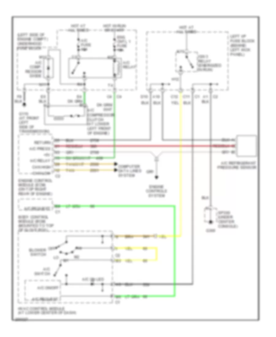
AIR CONDITIONING
Compressor Wiring Diagram for Saturn L300 2005
List of elements for Compressor Wiring Diagram for Saturn L300 2005:
- (left side of engine compt) underhood fuse block
- +5v
- A/c
- A/c comp- ressor diode
- A/c fuse 10a
- A/c on led
- A/c on/off
- A/c press
- A/c refrigerant pressure sensor
- A/c relay
- A/c request
- A/c switch
- A10
- Blower switch
- Body control module (bcm) (mounted to top of glove box)
- C11
- C12
- Can high
- Can low
- Compressor clutch (at lower left front of engine)
- Computer data lines system
- D10
- Eng cntl 1 fuse 10a
- Engine control module (ecm) (on top right rear of engine)
- Engine controls system
- G110 (at front left side of transmission)
- G300
- H12
- Hot at all times
- Hot in run or start
- Hvac control module (at lower center of dash)
- Ign 3 relay (energized in run)
- K11
- Left i/p fuse block (behind left kick panel)
- M11
- N11
- Off
- Return
- Sp300 (under center console)
- Tan
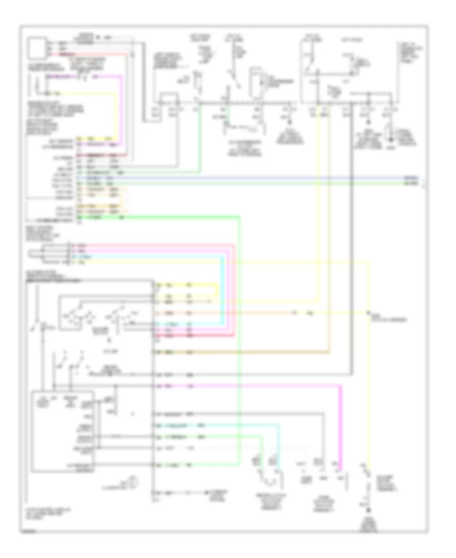
Manual A/C Wiring Diagram (1 of 2) for Saturn L300 2005
List of elements for Manual A/C Wiring Diagram (1 of 2) for Saturn L300 2005:
- (at rear of engine
- (left side of engine compt) underhood fuse block
- (on top right rear of engine) engine control module (ecm)
- +5v
- A/c compresser diode
- A/c compressor clutch (at lower left front of engine)
- A/c fuse 10a
- A/c led
- A/c on/off input
- A/c press
- A/c refrigerant pressure sensor
- A/c relay
- A/c request input
- A/c request output
- A/c switch
- A1 c2
- A10
- A12
- B11
- Blower motor (on hvac assembly)
- Blower motor resistor assembly (behind right side of dash)
- Blower switch
- Body control module (bcm) (mounted to top of glove box)
- C1 d10
- C11
- C12
- Can high
- Can low
- Compt, taped to engine harness)
- Def
- Def mode input
- Dim illumination
- Ect sensor
- Eng cntl 1 fuse 10a
- Engine controls system
- Engine coolant temperature (ect) sensor (in lower coolant passage of left cylinder head)
- F1 c1
- Fan 1 ctrl
- Fan 2 ctrl
- Fresh output
- G110 (at front left side of transmission)
- G300
- G304 (at left side of engine compt, near strut tower)
- G305 (under center console)
- Gnd
- H11
- H12
- Hot at all times
- Hot in run
- Hot in run or start
- Hvac control module (at lower center of dash)
- Ign
- Ign 3 fuse 10a
- Ign 3 relay
- Interior lights system
- K11
- K12
- Left i/p fuse block (behind left kick panel)
- Low reference
- M11
- Mode actuator (on hvac assembly)
- Mode input
- N11
- Off
- Pnk
- Recirc indicator
- Recirc on input
- Recirc output
- Recirculation actuator (on hvac assembly)
- Return
- S206 (in hvac harness)
- Sp105
- Sp300 (under center console)
- Tan
- Vent
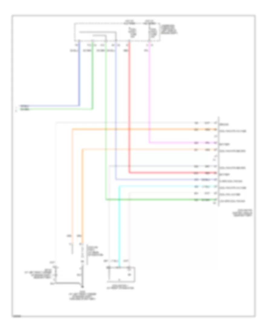
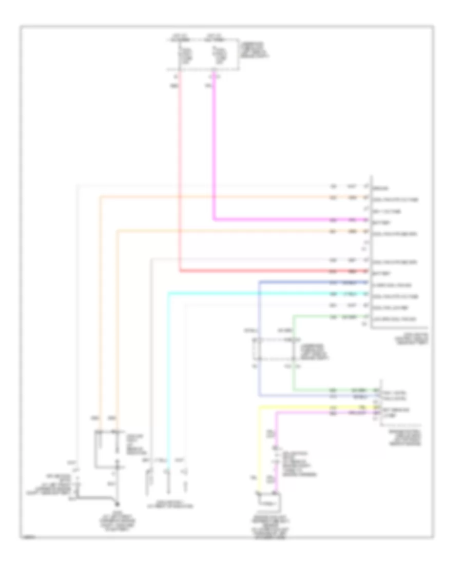
Manual A/C Wiring Diagram (2 of 2) for Saturn L300 2005
List of elements for Manual A/C Wiring Diagram (2 of 2) for Saturn L300 2005:
- A12
- Battery
- Cool fan 1 fuse 30a
- Cool fan 2 fuse 30a
- Cool fan low ref
- Cool fan mtr med spd
- Cool fan mtr voltage
- Cooling fan 1 (at front of radiator)
- Cooling fan 2 (at rear of radiator)
- Cooling fan control module (near battery)
- F12
- G105 (at left front corner of engine compt, forward of battery)
- Ground
- Hi spd cool fan sig
- Hot at all times
- Low spd cool fan sig
- Red
- Sp103 (at left front corner of engine compt, near battery)
- Underhood fuse block (left side of engine compt)
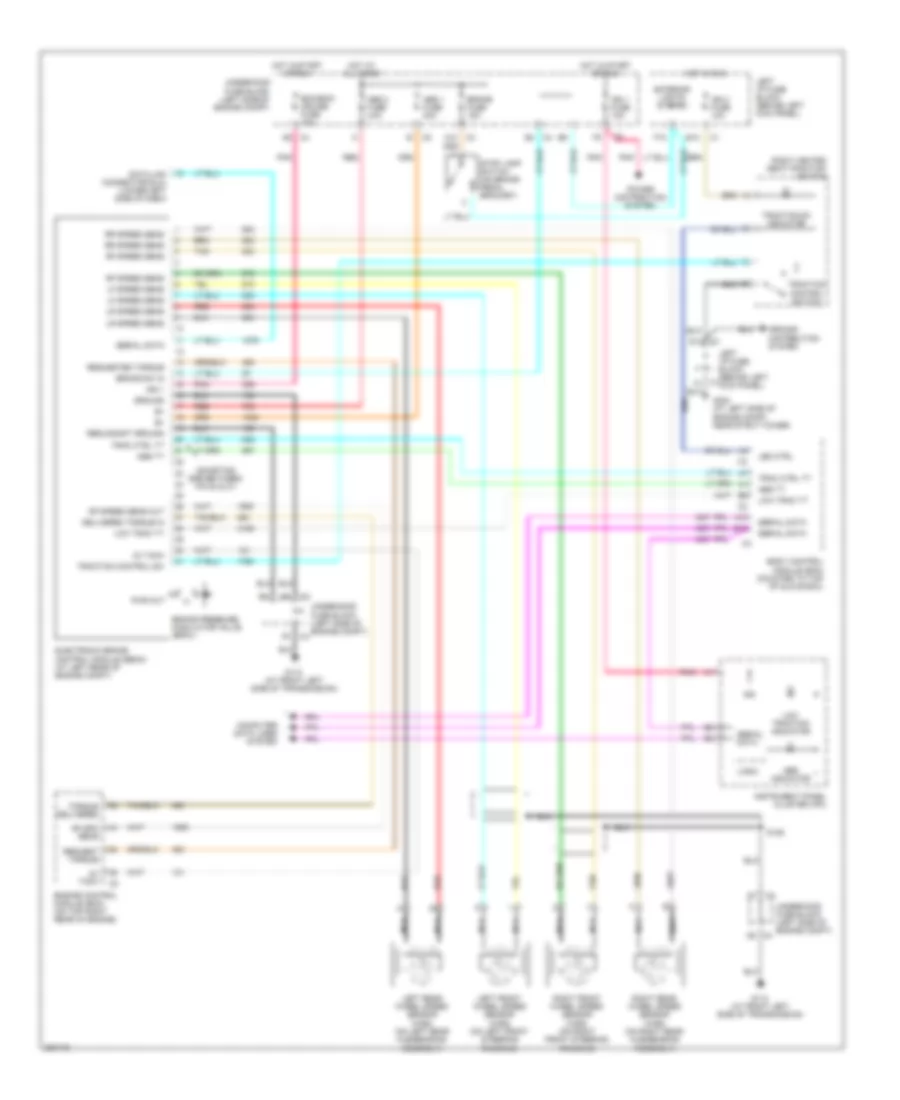
ANTI-LOCK BRAKES
Anti-lock Brakes Wiring Diagram for Saturn L300 2005
List of elements for Anti-lock Brakes Wiring Diagram for Saturn L300 2005:
- (shorting bar between pin 20 & 21)
- 2x tach
- A10
- Abs 1 fuse 30a
- Abs 2 fuse 30a
- Abs indicator
- Abs tt
- B10
- Bcm/ecm/ cruise fuse 10a
- Body control module (bcm) (mounted to top of glove box)
- Brake fuse 15a
- Brake pressure modulator valve (bpmv)
- Brake sw in
- C4 b4
- Computer data lines system
- D11 c1
- D8 c4
- Data link connector (dlc) (lower left side of dash)
- Delivered torque in
- E12
- Electronic brake control module (ebcm) (at left rear of engine compt)
- Engine control module (ecm) (on top right rear of engine)
- Exterior lights system
- F10
- G110 (at front left side of transmission)
- G304 (at left side of engine compt, near strut tower)
- Ground
- Ground distribution system
- Hot at all times
- Hot in run
- Hot in start or run
- Ign
- Ign 1
- Ign 1 fuse 10a
- Ign 3 fuse 10a
- Instrument panel cluster (ipc)
- Led ctrl
- Left front wheel speed sensor (wss) (on left front steering knuckle)
- Left i/p fuse block (behind left kick panel)
- Left rear wheel speed sensor (wss) (on left rear hub/bearing assembly)
- Lf speed sens
- Logic
- Low trac tt
- Low traction indicator
- Lr speed sens
- Nca
- Pnk
- Power distribution system
- Pwr out
- Red
- Redundant ground
- Request torque
- Requested torque
- Rf spd sens
- Rf speed sens
- Rf speed sens out
- Right front wheel speed sensor (wss) (on right front steering knuckle)
- Right heated seat/traction switch
- Right rear wheel speed sensor (wss) (on right rear hub/bearing assembly)
- Rr speed sens
- S128
- Serial data
- Stop lamp switch (on brake pedal bracket)
- Tan
- Torque delivered
- Trac ctrl tt
- Traction control sw
- Traction control switch
- Traction on indicator
- Underhood fuse block (left side of engine compt)
ANTI-THEFT
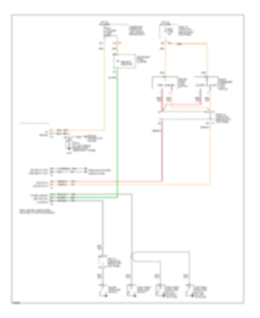
Forced Entry Wiring Diagram for Saturn L300 2005
List of elements for Forced Entry Wiring Diagram for Saturn L300 2005:
- (behind right kick panel)
- A12
- Bcm/ cluster fuse 15a
- Body control module (bcm) (mounted to top of glove box)
- Body fuse 10a
- C3 f12
- Driver door jamb switch
- Driver door lock switch
- Drl relay ctrl
- E11
- Front passenger door lock switch
- G191
- Ground
- Ground distribution system
- Headlights system
- Horn relay ctrl
- Horns system
- Hot at all times
- Instrument panel cluster
- Left i/p fuse block (behind left kick panel)
- Left rear door jamb switch (at left "b" pillar)
- Lf door in
- Lock
- Lock sw in
- Other jamb sw
- Right front door jamb switch
- Right i/p fuse block
- Right i/p fuse block (behind right kick panel)
- Right rear door jamb switch (at right "b" pillar)
- Sec ind ctrl
- Security indicator
- Sp191 (at left side of engine compt, near strut tower)
- Underhood fuse block (left side of engine compt)
- Unlock
- Unlock sw in
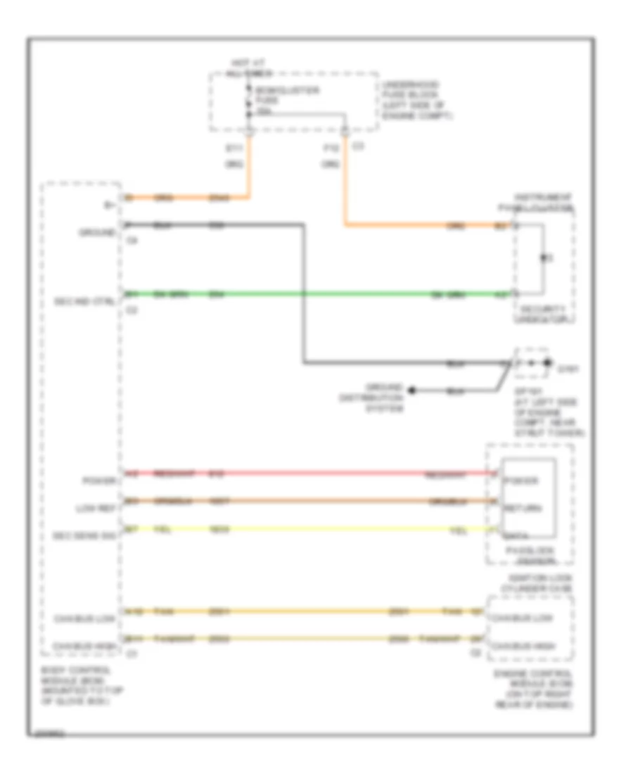
Passlock Wiring Diagram for Saturn L300 2005
List of elements for Passlock Wiring Diagram for Saturn L300 2005:
- A12
- B11
- Bcm/cluster fuse 15a
- Body control module (bcm) (mounted to top of glove box)
- Can bus high
- Can bus low
- Data
- E11
- Engine control module (ecm) (on top right rear of engine)
- F12
- G191
- Ground
- Ground distribution system
- Hot at all times
- Ignition lock cylinder case
- Instrument panel cluster
- Low ref
- Passlock sensor
- Power
- Return
- Sec ind ctrl
- Sec sens sig
- Security indicator
- Sp191 (at left side of engine compt, near strut tower)
- Tan
- Underhood fuse block (left side of engine compt)
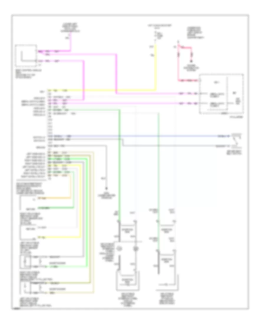
BODY CONTROL MODULES
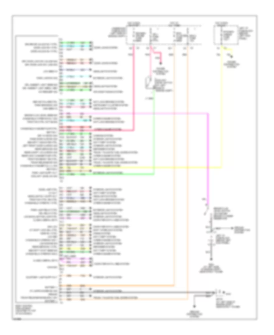
Body Control Modules Wiring Diagram for Saturn L300 2005
List of elements for Body Control Modules Wiring Diagram for Saturn L300 2005:
- (at left side of engine compt)
- (not used)
- 12 volt
- A/c request sig
- A/t shift lock sol ctrl
- A10
- A11
- A12
- Abs ind failure ctrl
- Air conditioning system
- Anti-lock brakes system
- Anti-theft system
- B10
- B11
- B12
- Battery +
- Bcm 2 fuse 10a
- Bcm/ cluster fuse 15a
- Bcm/ecm/ cruise fuse 10a
- Body control module (bcm) (mounted to top of glove box)
- Brake fluid level sens sig
- Brake fluid level switch (on master brake cylinder reservoir)
- Btsi/bcm mirror fuse 10a
- C1 f1
- C11
- Can high
- Can low
- Class 2 serial data
- Computer data lines system
- Coolant level sw sig
- Coolant level switch
- Courtesy lamp supp volt
- Defogger system
- Dome lamp ctrl
- Door lock rly ctrl
- Door locks system
- Door unlock rly ctrl
- Driver dr unlock rly ctrl
- Drl ambient light sens l ref
- Drl ambient light sens sig
- Drl relay ctrl
- Drv door lock sw lock sig
- Drv door lock sw unlock sig
- E11
- Exterior lights system
- G191
- G304 (at left side of engine compt, near strut tower
- Ground
- Ground distribution system
- Headlamp rly supp volt
- Headlights system
- High beam in
- Horn rly ctrl
- Horns system
- Hot at all times
- Hot in run or acc
- Hot in run or start
- I/p lamps dimmer sw sig
- Ign 1 fuse 10a
- Ignition 1
- Ignition 2
- Instrument cluster system
- Interior lights system
- Key in ign sw sig
- Lcd backlighting lamp ctrl
- Lcd dimming sig
- Left front door ajar sw sig
- Left i/p fuse block (behind left kick panel)
- Low beam in
- Low ref
- Park brake sw sig
- Park lamp relay ctrl
- Park lamp supp volt
- Park lamp sw sig
- Pass door ajar sw sig
- Pnk
- Power distribution system
- Rear compt lid ajar sw sig
- Rear defog rly ctrl
- Rear defog sw sig
- Rear wdw washer pump ctrl
- Red
- Security indicator ctrl
- Security syst sens sig
- Shift interlock system
- Sp191 (at left side of engine compt, near strut tower)
- Tan
- Traction ctrl active sig
- Traction ctrl idn ctrl
- Traction ready ind ctrl
- Trunk release enable rly sw
- Trunk release sw sig
- Trunk, tailgate, fuel doors system
- Underhood fuse block (left side of engine compt)
- Warning system
- Windshield washer fld lvl sig
- Windshield washer pump ctrl
- Windshield wiper rly ctrl
- Windshield wiper sw dly sig
- Windshield wiper sw sig 1
- Windshield wiper sw sig 2
- Wiper/washer system
COMPUTER DATA LINES
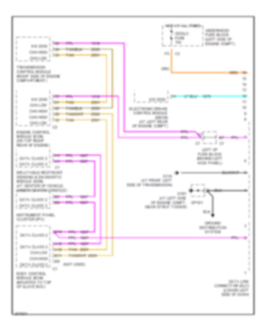
Computer Data Lines Wiring Diagram for Saturn L300 2005
List of elements for Computer Data Lines Wiring Diagram for Saturn L300 2005:
- data class 2
- (not used)
- A10
- A12
- B10
- B11
- Body control module (bcm) (mounted to top of glove box)
- Can high
- Can low
- Cd/dlc fuse 15a
- Data class 2
- Data link connector (dlc) (lower left side of dash)
- Electronic brake control module (ebcm) (at left rear of engine compt)
- Engine control module (ecm) (on top right rear of engine)
- G110 (at front left side of transmission)
- G191 (at left side of engine compt, near strut tower)
- Ground distribution system
- Hot at all times
- Inflatable restraint sensing & diagnostic module (sdm) (at center of vehicle, under center console)
- Instrument panel cluster (ipc)
- Kw 2000
- Left i/p fuse block (behind left kick panel)
- Sp191
- Tan
- Transmission control module (right side of engine compartment)
- Underhood fuse block (left side of engine compt)
COOLING FAN
Cooling Fan Wiring Diagram for Saturn L300 2005
List of elements for Cooling Fan Wiring Diagram for Saturn L300 2005:
- A12
- Battery
- Cool fan 1 fuse 30a
- Cool fan 2 fuse 30a
- Cool fan low ref
- Cool fan mtr med spd
- Cool fan mtr voltage
- Cooling fan 1 (at front of radiator)
- Cooling fan 2 (at rear of radiator)
- Cooling fan control module (near battery)
- Ect sens sig
- Engine control module (ecm) (on top right rear of engine)
- Engine coolant temperature (ect) sensor (in lower coolant passage of left cylinder head)
- F12
- Fan 1 cntrl
- Fan 2 cntrl
- G105 (at left front corner of engine compt, forward of battery)
- Ground
- Hi spd cool fan sig
- Hot at all times
- Ign 1 voltage
- Lo ref
- Low spd cool fan sig
- Red
- Splice pack sp103 (at left front corner of engine compt, near battery)
- Splice pack sp105 (at rear of engine compt, taped to engine harness)
- Underhood fuse block (left side of engine compt)
CRUISE CONTROL
Cruise Control Wiring Diagram for Saturn L300 2005
List of elements for Cruise Control Wiring Diagram for Saturn L300 2005:
- (in steering wheel jumper harness, under inflatable restraint steering wheel module) s202
- 5v ref app 2
- 5v ref app1
- 5v tp sens 1 & 2
- A10
- Accelerator pedal position (app) sensor (on accelerator pedal linkage arm)
- All times
- App sens sig 1
- App sens sig 2
- Automatic transmission output speed sensor (oss)
- B10
- Bcm/ecm/ cruise fuse 10a
- Brake fuse 15a
- Can high
- Can low
- Cruise brake in
- Cruise on/off
- Cruise on/off switch
- Cruise set/coast
- Cruise set/resume switch
- Cruise switch fuse 2a
- Cruise w/ off ind
- D10
- D12
- E12
- Engine control module (ecm) (on top right rear of engine)
- F10
- Grounded to steering wheel
- Hot at
- Hot in run or start
- Inflatable restraint steering wheel module coil (under steering wheel)
- Left i/p fuse block (behind left kick panel)
- Low ref
- Low ref app 1
- Low ref app 2
- Nca
- Off
- Pnk
- Resume/ accel
- Resume/accel
- Set/ coast
- Splice pack sp105 (at rear of engine compartment, taped to engine harness)
- Stp lmp sw input
- Tac motor ctrl 1
- Tac motor ctrl 2
- Tan
- Throttle actuator control (tac) module (at top front of engine, on throttle body)
- Tp sensor sig 1
- Tp sensor sig 2
- Transmission control module (ecm) (right side of engine compt)
- Underhood fuse block (left side of engine compt)
- Vss high sig
- Vss low sig
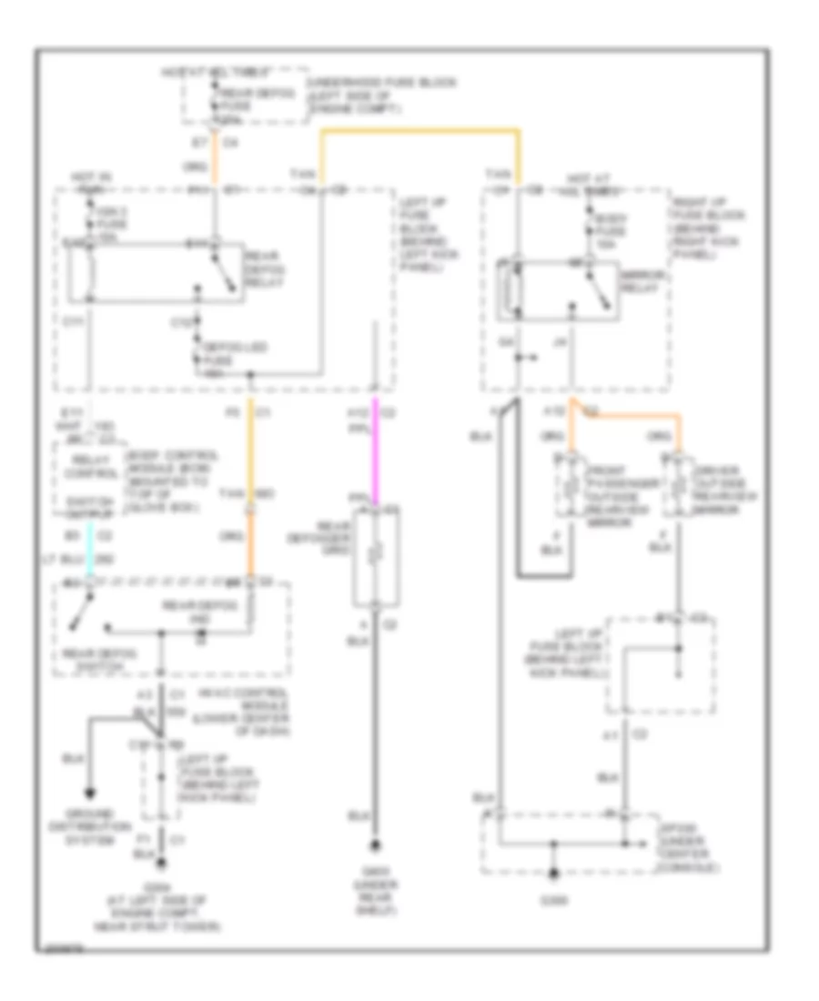
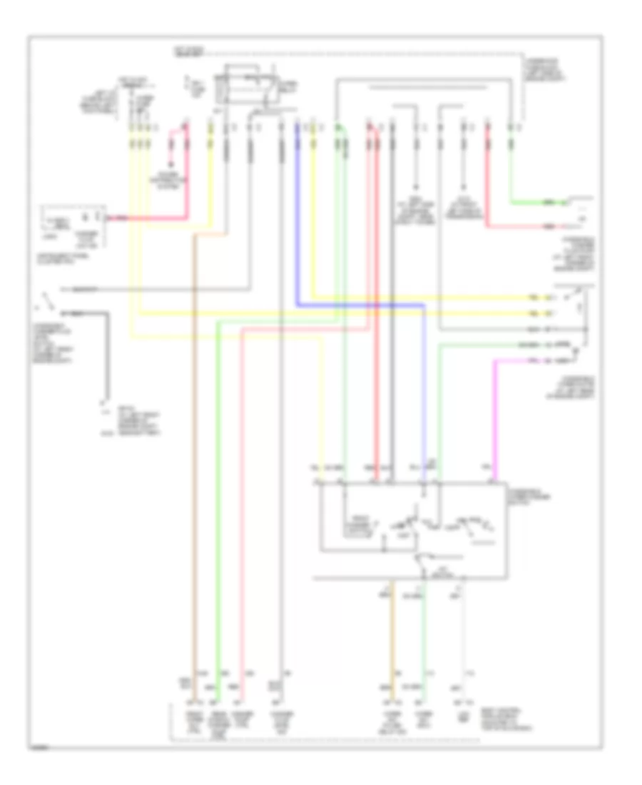
DEFOGGERS
Defoggers Wiring Diagram for Saturn L300 2005
List of elements for Defoggers Wiring Diagram for Saturn L300 2005:
- (at left side of engine compt, near strut tower)
- A12
- A12 c2
- Body control module (bcm) (mounted to top of glove box)
- Body fuse 10a
- C11
- C12
- Defog led fuse 10a
- Driver outside rearview mirror
- E11
- E12
- F11
- Front passenger outside rearview mirror
- G300
- G304
- G400 (under rear shelf)
- Ground distribution system
- Hot at all times
- Hot in run
- Hvac control module (lower center of dash)
- Ign 3 fuse 10a
- Left i/p fuse block (behind left kick panel)
- Mirror relay
- Rear defog fuse 25a
- Rear defog ind
- Rear defog relay
- Rear defog switch
- Rear defogger grid
- Relay control
- Right i/p fuse block (behind right kick panel)
- Sp300 (under center console)
- Switch output
- Tan
- Underhood fuse block (left side of engine compt)
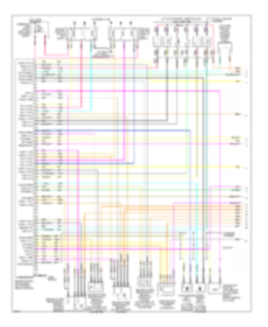
ENGINE PERFORMANCE
3.0L VIN R
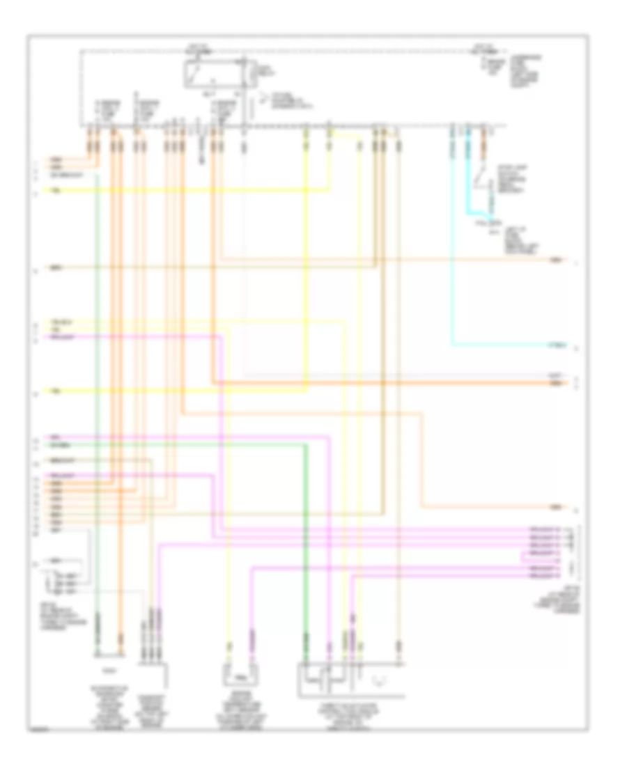
3.0L VIN R, Engine Performance Wiring Diagram (1 of 3) for Saturn L300 2005
List of elements for 3.0L VIN R, Engine Performance Wiring Diagram (1 of 3) for Saturn L300 2005:
- (at front left side of g110 transmission)
- (at top of engine, under fuel rail)
- (in engine harness)
- (in fuel injector harness)
- (in intake manifold) intake manifold runner control (imrc) solenoid
- Case ground
- Ckp hi
- Ckp lo
- Cmp sens
- Coil 1 ctrl
- Coil 3 ctrl
- Coil 4 ctrl
- Coil 5 ctrl
- Coil 6 ctrl
- Crankshaft position (ckp) sensor on left rear side of engine, behind oil filter
- E10
- Ect sens
- Engine control module (ecm) (on top right rear of engine)
- Evap purge
- F10
- Fuel inj 1
- Fuel inj 2
- Fuel inj 3
- Fuel inj 4
- Fuel inj 5
- Fuel inj 6
- Fuel injectors
- Heated oxygen sensor bank 1 sensor 1 (on right exhaust manifold)
- Heated oxygen sensor bank 1 sensor 2 (in exhaust system, downstream of bank 1 catalytic converter)
- Heated oxygen sensor bank 2 sensor 1 (on left exhaust manifold)
- Heated oxygen sensor bank 2 sensor 2 (in exhaust system, downstream of bank 1 catalytic converter)
- Ho2s 1,1 htr
- Ho2s 1,1 in
- Ho2s 1,1 out
- Ho2s 1,1 ref
- Ho2s 1,1 sig
- Ho2s 1,2 hi
- Ho2s 1,2 htr
- Ho2s 1,2 lo
- Ho2s 2,1 htr
- Ho2s 2,1 in
- Ho2s 2,1 out
- Ho2s 2,1 ref
- Ho2s 2,1 sig
- Ho2s 2,2 hi
- Ho2s 2,2 lo
- Hot in run or start
- Iat sens
- Ign fuse 15a
- Ignition control module (icm) bank 1
- Ignition control module (icm) bank 2
- Intk plenum
- Knock sens
- Knock sensor (ks) 1 (for cyl 1, 3, 5) (at lower right side of engine)
- Knock sensor (ks) 2 (for cyl 2, 4, 6) (at lower left side of engine)
- Maf sens
- Mass air flow (maf) sensor (on air intake duct)
- Nca
- Pnk
- S101
- S140
- Sensor +5v
- Sensor rtn
- Shld ground
- Tan
- Throttle hi
- Throttle lo
- To spark plugs
- Tps +5v
- Tps sens 1
- Tps sens 2
- Underhood fuse block (left side of engine compt)
3.0L VIN R, Engine Performance Wiring Diagram (2 of 3) for Saturn L300 2005
List of elements for 3.0L VIN R, Engine Performance Wiring Diagram (2 of 3) for Saturn L300 2005:
- (not used)
- A10
- B10
- Brake fuse 15a
- Camshaft position sensor (on top left front of engine)
- D12
- E12
- Engine cntl 1 fuse 10a
- Engine cntl 2 fuse 10a
- Engine cntl 3 fuse 10a
- Engine coolant temperature (ect) sensor (in lower coolant passage of left cylinder head)
- Evaporative emissions (evap) canister purge solenoid (at right side of engine)
- F10
- Hot at all times
- Left i/p fuse block (behind left kick panel)
- Main relay
- Nca
- Sp105 (at rear of engine compt, taped to engine harness)
- Stop lamp switch (on brake pedal bracket)
- Throttle actuator control (tac) module (at top front of engine, on throttle body)
- To fuel pump relay (diagram 3 of 3)
- Underhood fuse block (left side of engine compt)
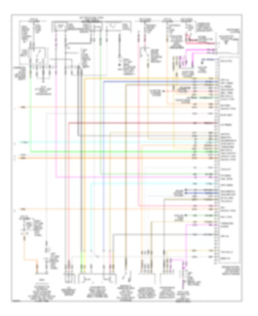
3.0L VIN R, Engine Performance Wiring Diagram (3 of 3) for Saturn L300 2005
List of elements for 3.0L VIN R, Engine Performance Wiring Diagram (3 of 3) for Saturn L300 2005:
- (mounted to top of glove box) body control module (bcm)
- (on top of fuel tank) fuel pump & sender assembly
- A/c press
- A/c refrigerant pressure sensor
- A/c rly ctrl
- A10
- A12
- Accelerator
- Air conditioning system
- App +5v
- App 1 sens
- App 2 sens
- App rtn
- B10
- B11
- Battery
- Bcm can hi
- Bcm can lo
- Bcm/ecm/ cruise fuse 10a
- Body fuse 10a
- C10
- C11
- Computer data lines system
- Controls b+ fuse 10a
- Cooling fans system
- Cruise brake switch (on brake pedal bracket)
- Cruise control system
- Cruz on/off
- Cruz res/acl
- Cruz set/cst
- Cruz/brake in
- D10
- D12
- Data link connector (dlc) (lower left side of dash)
- Electronic brake control module (ebcm) (at left rear of engine compt)
- Engine control module (ecm) (on top right rear of engine)
- Engine oil pressure (eop) switch (on oil pump housing, on lower front of engine)
- Evap vent
- Evaporative emissions (evap) canister vent solenoid (at rear of the vehicle, near the fuel tank filler tube)
- Fan 1 ctrl
- Fan 2 ctrl
- From engine ctrl3 fuse (diagram 2 of 3)
- Ftp sens
- Fuel level
- Fuel level sensor
- Fuel pump fuse 15a
- Fuel pump motor
- Fuel pump relay
- Fuel pump rly
- Fuel tank pressure sensor
- G110 (at front left side of transmission)
- G401
- Gen l term
- H11
- H12
- Hot at all times
- Hot in run or start
- Ign 1
- Ign 1 fuse 10a
- Instrument cluster
- J11
- K11
- K12
- Kw2000
- Left i/p fuse block (behind c2 (left kick panel)
- Left i/p fuse block (behind left kick panel) c1
- Left i/p fuse block c2 (behind left kick panel)
- Logic
- Main rly ctrl
- Main rly pwr
- Malfunction indicator lamp
- Oil press
- Pedal position (app) sensor (on accelerator pedal linkage arm)
- Pnk
- Power distribution system
- Red
- Rf whl spd
- Right i/p fuse block (behind right kick panel)
- Sens +5v
- Sens rtn
- Sp401 (at left rear of vehicle, near left taillight assembly)
- Starting/ charging system
- Stoplamp in
- Tach out
- Tan
- Tcm can hi
- Tcm can lo
- Torque del
- Torque req
- Transmission control module (tcm) (right side of engine compt)
- Underhood fuse block (left side of engine compt)
EXTERIOR LIGHTS
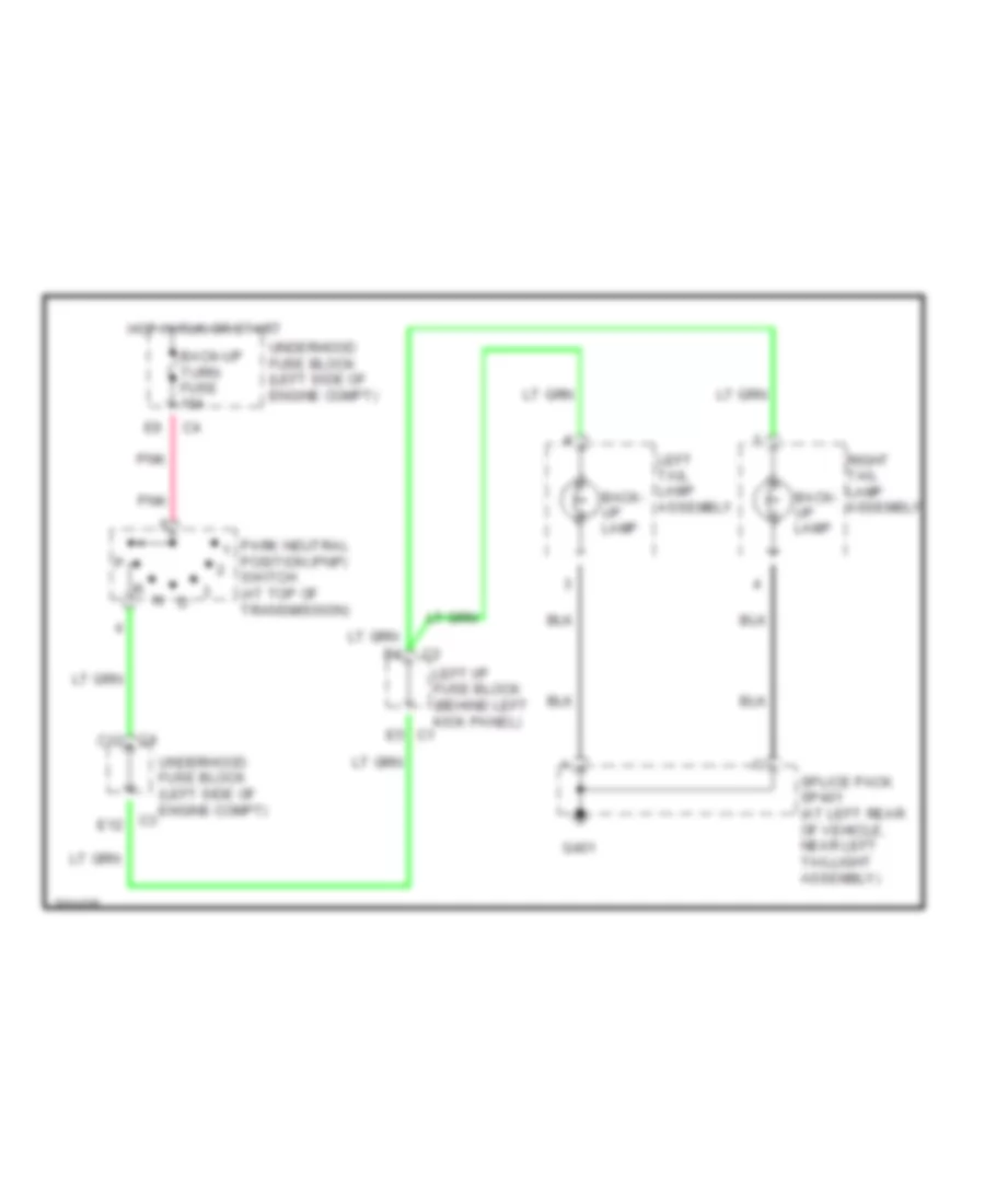
Back-up Lamps Wiring Diagram for Saturn L300 2005
List of elements for Back-up Lamps Wiring Diagram for Saturn L300 2005:
- Back- up lamp
- Back-up turn fuse 10a
- C3 e12
- C4 c12
- E5 c1
- G401
- Hot in run or start
- Left i/p fuse block (behind left kick panel)
- Left tail lamp assembly
- Park neutral position (pnp) switch (at top of transmission)
- Pnk
- Right tail lamp assembly
- Splice pack sp401 (at left rear of vehicle, near left taillight assembly)
- Underhood fuse block (left side of engine compt)
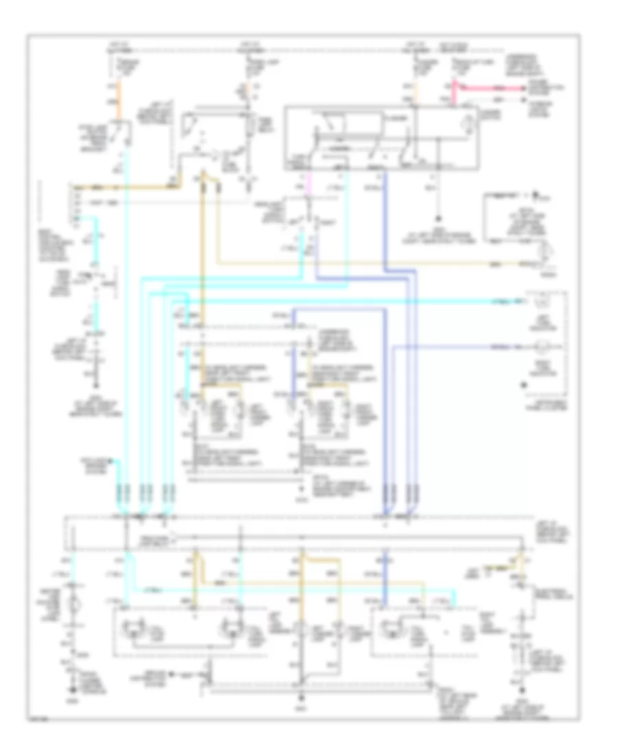
Exterior Lamps Wiring Diagram for Saturn L300 2005
List of elements for Exterior Lamps Wiring Diagram for Saturn L300 2005:
- (not used)
- A10
- A12
- Anti-lock brakes system
- Auto
- B10
- B11
- B12
- B9 c2
- Back-up turn fuse 10a
- Body control module (bcm) (mounted to top of glove box)
- Brake fuse 15a
- C10
- Center high mounted stop lamp (chmsl)
- E10
- Electronic prndl module
- F1 c1
- F10
- Flasher
- From park a lamp relay
- G103
- G191
- G300
- G304 (at left side of engine compt, near strut tower)
- G401
- Ground distribution system
- Hazard
- Hazard fuse 15a
- Hazard switch
- Head
- Head lamp/ turn signal switch
- Headlamp/ turn signal switch left
- Hot at all times
- Hot in run or start
- Instrument panel cluster
- Interior lights system
- Left
- Left front marker lamp
- Left front park/ turn signal lamp
- Left i/p fuse block (behind left kick panel)
- Left license lamp
- Left tail lamp assembly
- Left turn indicator
- Off
- Park
- Park lamp fuse 10a
- Park lamp relay
- Park/turn signal light) s106
- Pnk
- Power distribution system
- Radio
- Right
- Right front marker lamp
- Right front park/ turn signal lamp
- Right license lamp
- Right tail lamp assembly
- Right turn indicator
- S107 (in headlight harness, near left front park/turn signal light)
- S308
- Sp103 (at left corner of engine compartment, near battery)
- Sp191 (at left side of engine compt, near strut tower)
- Sp300 (under center console)
- Sp401 (at left rear of vehicle, near left taillight assembly)
- Stop lamp switch (on brake pedal bracket)
- Tail/ stop lamp
- Tail/ turn signal lamp
- To left i/p fuse block
- Turn signal feed
- Underhood fuse block (left side of engine compt)
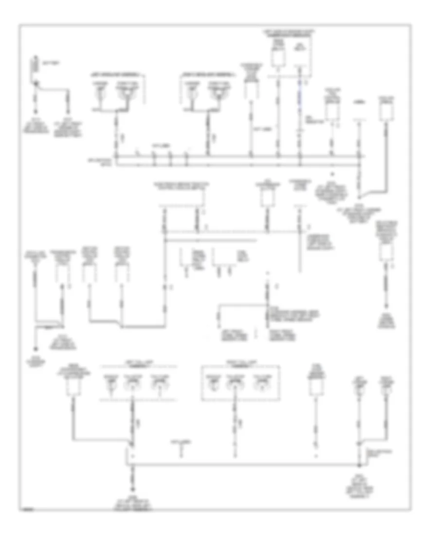
GROUND DISTRIBUTION
Ground Distribution Wiring Diagram (1 of 2) for Saturn L300 2005
List of elements for Ground Distribution Wiring Diagram (1 of 2) for Saturn L300 2005:
- (left side of engine compt) underhood fuse block
- (not used) f
- A/c compressor clutch
- A11
- A18
- Backup lamp
- Battery
- C102
- C103
- C4 underhood fuse block (left side of engine compt)
- C498
- C499
- Cooling fan 2
- Cooling fan control module
- Data link connector (dlc)
- Drl relay
- Drl resistor
- Electronic brake traction control module (ebtcm)
- Fuel pump relay
- Fuel pump sender assembly
- G102 (in engine compt)
- G103 (at left front of engine compt, near windshield washer fluid tank)
- G105 (at left front corner of engine compt, forward of battery)
- G107 (at left front corner of engine compt, near battery)
- G110 (at front left side of transmission)
- G113 (at front left side of transmission)
- G303 (under center console)
- G399 (at left rear of vehicle, near left taillight assembly)
- G401 (at left rear of vehicle, near left taillight assembly)
- Horn
- Ignition control module (icm) bank 1
- Ignition control module (icm) bank 2
- Inflatable restraint sensing & diagnostic module (sdm)
- J11
- K12
- Left front wheel speed sensor (wss)
- Left headlamp assembly
- Left license lamp
- Left tail lamp assembly
- Marker lamp
- Nca
- Not used
- Park/turn signal lamp
- Rear compartment lid ajar/release actuator
- Rear wiper relay
- Rear wiper relay (not used)
- Right front wheel speed sensor (wss)
- Right headlamp assembly
- Right license lamp
- Right tail lamp assembly
- Splice pack sp103
- Splice pack sp401
- Tail/stop lamp
- Tail/turn lamp
- Transmission control module (tcm)
- Windshield washer fluid level switch
- Windshield wiper motor
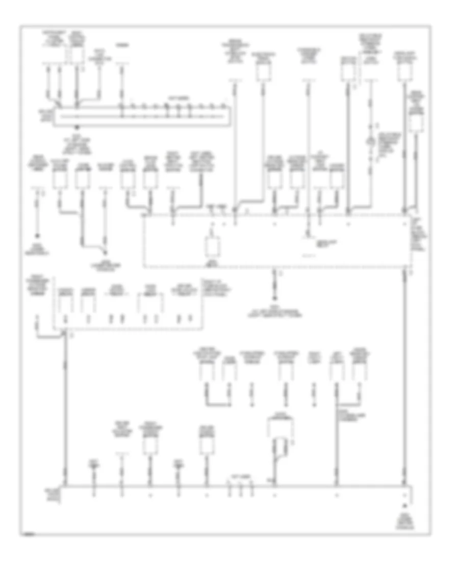
Ground Distribution Wiring Diagram (2 of 2) for Saturn L300 2005
List of elements for Ground Distribution Wiring Diagram (2 of 2) for Saturn L300 2005:
- (if equipped) sunroof module
- (if equipped) sunroof switch
- (not used)
- (not used) left heated seat/fog lamp switch connector
- A12
- Audio amplifier
- Auxiliary power outlet
- B11
- Blower motor
- Body control module (bcm)
- Brake fluid level switch
- Brake transmission shift interlock (btsi) switch
- C1 left i/p fuse block (behind left kick panel)
- C11
- Center high mounted stop lamp (chmsl)
- Cigar lighter
- D11
- Data link connector (dlc)
- Dome lamp
- Door lock relay
- Door unlock relay
- Driver door unlock relay
- Driver outside rearview mirror
- Driver seat adjuster switch
- Driver window switch
- Electronic prndl module
- Front passenger outside rearview mirror
- Front passenger window switch
- G191 (at left side of engine compt, near strut tower)
- G300 (under center console)
- G304 (at left side of engine compt, near strut tower)
- G305 (under center console)
- G400 (under rear shelf)
- H11
- Hazard switch
- Headlamp relay
- Headlamp/ turn signal switch
- Horn switch
- Hvac control module
- I/p compart- ment lamp switch
- Ign3 relay
- Ignition switch
- Inflatable restraint steering wheel module
- Inflatable restraint steering wheel module coil c4
- Inside rearview mirror (isrvm)
- Instrument panel cluster (ipc)
- K12
- Left vanity lamp
- Mirror relay
- Not used
- Outside rearview mirror switch
- Radio
- Rear compart- ment lid/ dimmer switch
- Rear window defogger grid
- Right heated seat/ traction switch
- Right i/p fuse block (behind right kick panel)
- Right vanity lamp
- S308 (in headliner harness)
- Splice pack sp191
- Splice pack sp300
- Window relay
- Windshield washer/ wiper switch
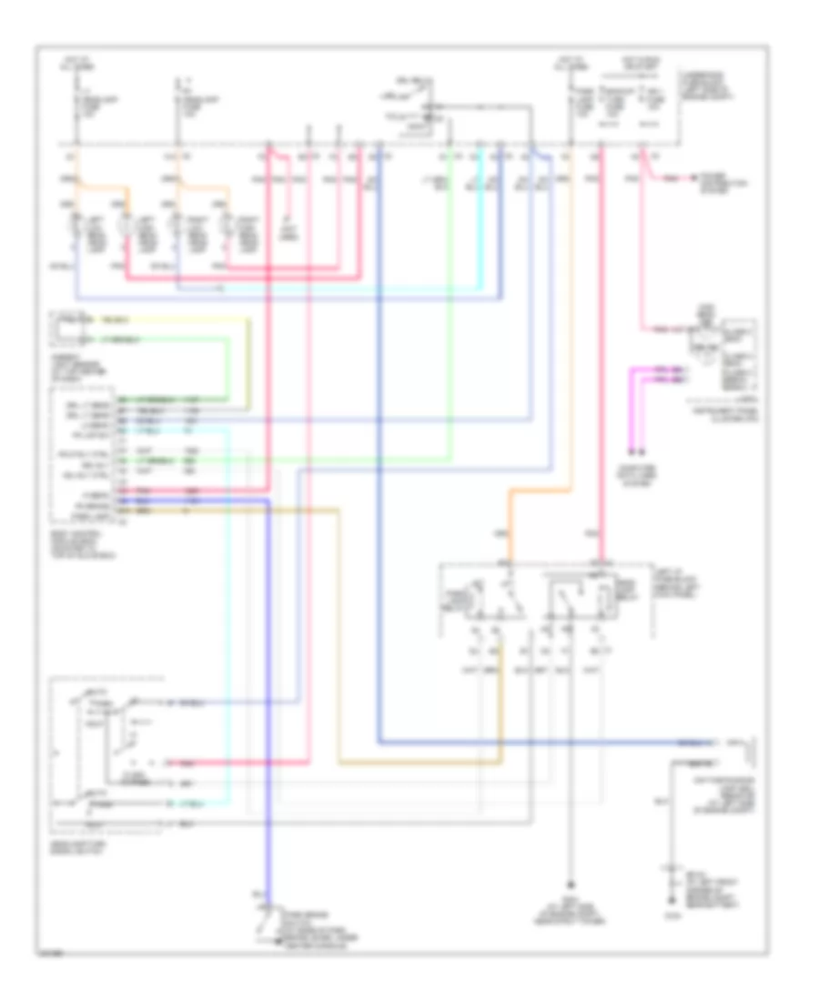
HEADLIGHTS
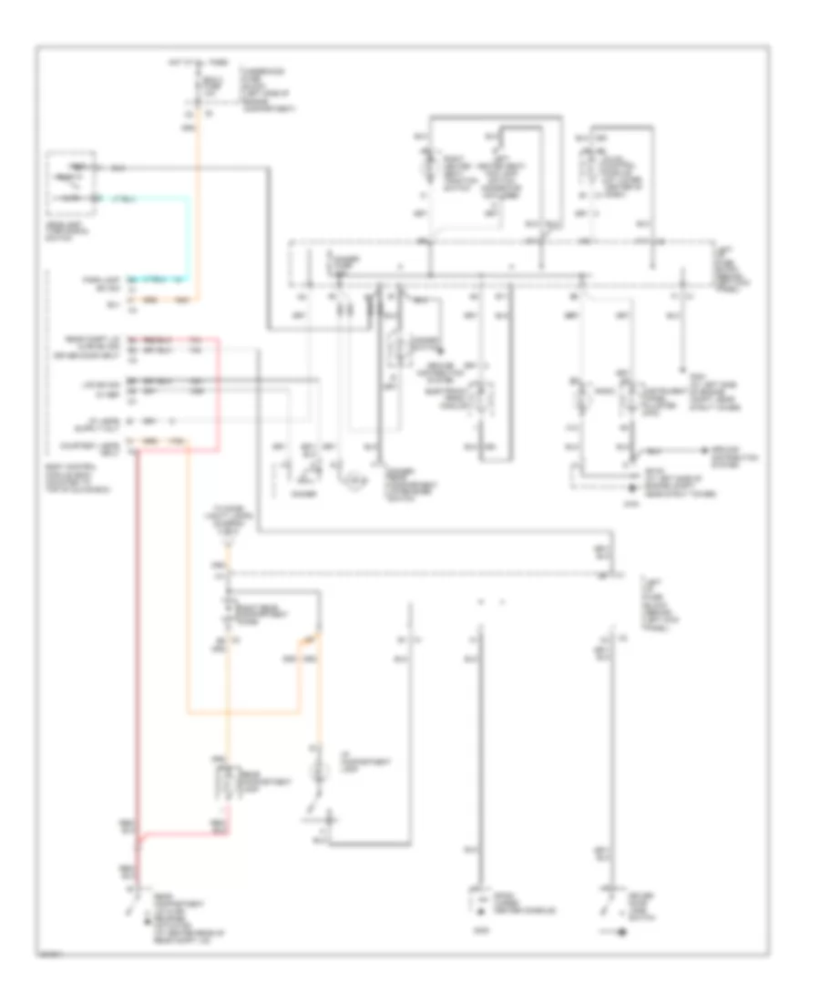
Headlights Wiring Diagram for Saturn L300 2005
List of elements for Headlights Wiring Diagram for Saturn L300 2005:
- (not used)
- Ambient light sensor (at top center of dash)
- Auto
- B10
- Backup/ turn fuse 10a
- Body control module (bcm) (mounted to top of glove box)
- C1 e8
- C2 a3
- C2 d2
- C2 f10
- C3 d1
- C3 e3
- C9 c1
- Class 2 (bcm)
- Class 2 serial data
- Computer data lines system
- Corner of engine compt, near battery)
- Daytime running lamp (drl) resistor (at left side of engine compt)
- Drl ind
- Drl lt sens
- Drl relay
- Drl rly
- Flash to pass
- G103
- G304 (at left side of engine compt, near strut tower)
- Hdl rly ctrl
- Hdlp
- Head lamp relay
- Headlamp/turn signal switch
- Hi beam
- High beam ind
- Hot at all times
- Hot in run or start
- Ign 1 fuse 10a
- Instrument panel cluster (ipc)
- Left high beam head- lamp
- Left i/p fuse block (behind left kick panel)
- Left low beam head- lamp
- Lo beam
- Logic
- Lt headlamp fuse 10a
- Park
- Park brake switch (at base of park brake lever, under center console)
- Park lamp
- Park lamp fuse 10a
- Park lamp relay
- Pk brake
- Pk lmp sw
- Pklp rly ctrl
- Pnk
- Power distribution system
- Right high beam head- lamp
- Right low beam head- lamp
- Rt headlamp fuse 10a
- Sp103 (at left front
- Underhood fuse block (left side of engine compt)
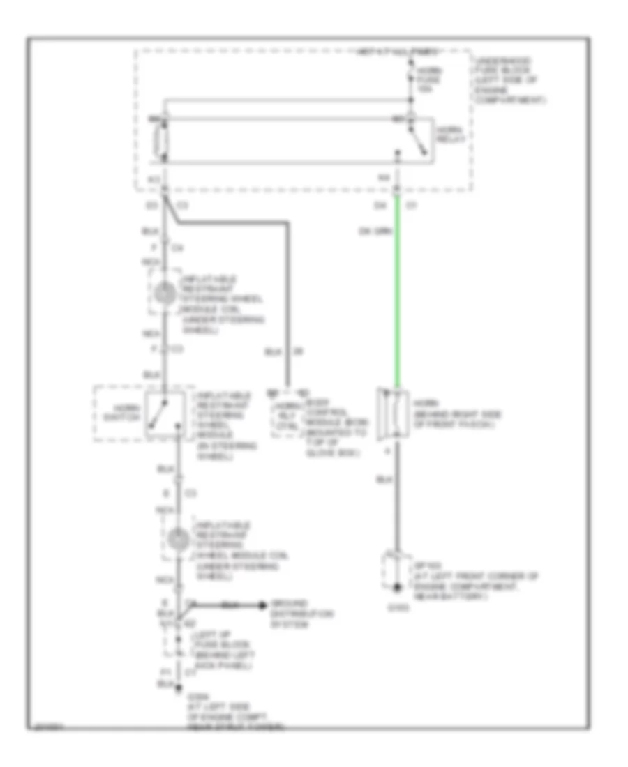
HORN
Horn Wiring Diagram for Saturn L300 2005
List of elements for Horn Wiring Diagram for Saturn L300 2005:
- (in steering wheel)
- (under steering wheel)
- Body control module (bcm) (mounted to top of glove box)
- G103
- G304 (at left side of engine compt, near strut tower)
- Ground distribution system
- Horn (behind right side of front fascia)
- Horn fuse 10a
- Horn relay
- Horn rly ctrl
- Horn switch
- Hot at all times
- Inflatable restraint steering wheel module
- Inflatable restraint steering wheel module coil
- Inflatable restraint steering wheel module coil (under steering wheel)
- Left i/p fuse block (behind left kick panel) c1
- Nca
- Sp103 (at left front corner of engine compartment, near battery)
- Underhood fuse block (left side of engine compartment)
INSTRUMENT CLUSTER
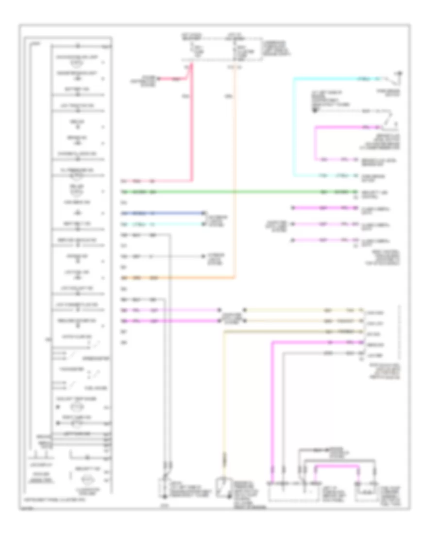
Instrument Cluster Wiring Diagram for Saturn L300 2005
List of elements for Instrument Cluster Wiring Diagram for Saturn L300 2005:
- (at left side of engine compartment, near strut tower) g304
- 000000 trip
- A10
- A10 c1
- A8 c2
- Abs ind
- Air bag ind
- B10
- Battery ind
- Bcm/ cluster fuse 15a
- Body control module (bcm) (mounted to top of glove box)
- Brake fluid level sensor sig
- Brake fluid level switch (on master brake cylinder reservoir)
- Brake ind
- C11
- Can high
- Can low
- Change oil soon ind
- Class 2 serial data
- Computer data lines system
- Coolant temp gauge
- Drl ind
- Engine control module (ecm) (on top right rear of engine)
- Engine controls system
- Engine oil pressure (eop) switch (on oil pump housing, on lower front of engine)
- Exterior lights system
- F12 c3
- Fuel gauge
- Fuel pump & sender assembly (on top of fuel tank)
- G191
- Ground
- Hatch ajar ind
- High beam ind
- Hot at all times
- Hot in run or start
- Ign
- Ign 1 fuse 10a
- Illumination (6 bulbs)
- Instrument panel cluster (ipc)
- Interior lights system
- Km/miles
- Lcd display
- Left i/p fuse block (behind left kick panel)
- Left turn ind
- Logic
- Low coolant ind
- Low fuel ind
- Low ref
- Low traction ind
- Low washer fluid ind
- Malfunction ind lamp
- Odometer backlight
- Oil pressure ind
- Park brake sw sig
- Park brake switch
- Pnk
- Power distribution system
- Reduced power ind
- Right turn ind
- Seat belt ind
- Security ind
- Security led control
- Sens sig
- Serial data
- Service vehicle ind
- Sp191 (at left side of engine compartment, near strut tower)
- Speedometer
- Sw sig
- Tachometer
- Tan
- Underhood fuse block (left side of engine compt)
INTERIOR LIGHTS
Interior Lights Wiring Diagram (1 of 2) for Saturn L300 2005
List of elements for Interior Lights Wiring Diagram (1 of 2) for Saturn L300 2005:
- 5v ref
- A12
- Auto
- B(+)
- B1 c1
- B11
- Bcm 2 fuse 10a
- Body control module (bcm) (mounted to top of glove box)
- C1 b1
- C1 f1
- C11
- C2 b5
- Courtesy lamps input
- D11
- Dimmer
- Dimmer fuse 10a
- Dimmer/ rear compartment lid release switch
- Driver door input
- Driver door jamb switch
- Electronic prndl module
- G191
- G300
- G304 (at left side of engine compt, near strut tower)
- Ground distribution system
- Hazard switch
- Head
- Headlamp turn signal switch
- Hot at all times
- Hvac control module (at lower center of dash)
- I/p compartment lamp
- Instrument panel cluster (ipc)
- Lcd dim sig
- Left heated seat/ fog lamp switch connector (not used)
- Left i/p fuse block (behind left kick panel)
- Park
- Park lamp sw sig
- Radio
- Rear compartment lamp
- Rear compartment lid ajar/ release actuator (at center rear of rear compt lid)
- Rear compt lid ajar sw sig
- Right heated seat/ traction switch
- Right rear compartment diode
- Sp191 (at left side of engine compt, near strut tower)
- Sp300 (under center console)
- To dome/ vanity lamps (diagram 2 of 2)
- Underhood fuse block (left side of engine compartment)
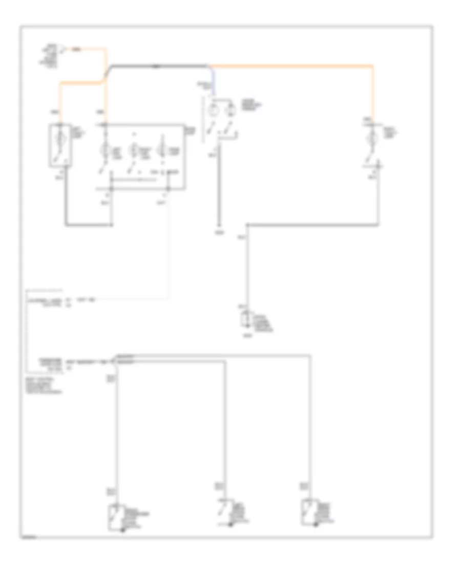
Interior Lights Wiring Diagram (2 of 2) for Saturn L300 2005
List of elements for Interior Lights Wiring Diagram (2 of 2) for Saturn L300 2005:
- A12
- Body control module (bcm) (mounted to top of glove box)
- Courtesy lamps low ctrl
- Dome lamp
- Door
- From left i/p a fuse block (diagram 1 of 2)
- Front passenger door jamb switch
- G300
- Inside rearview mirror
- Left map lamp
- Left rear door jamb switch
- Left vanity lamp
- Nca
- Passenger door ajar sw sig
- Right map lamp
- Right rear door jamb switch
- Right vanity lamp
- S308
- Sp300 (under center console)
POWER DISTRIBUTION
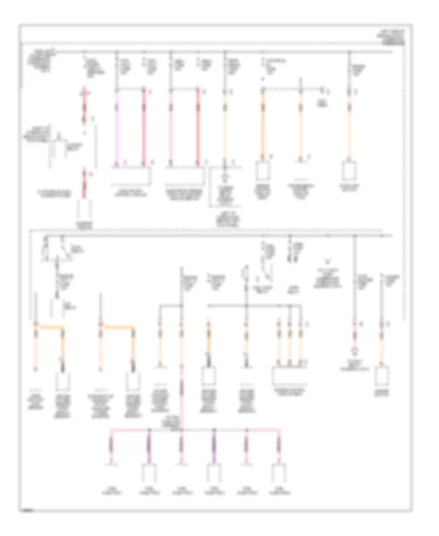
Power Distribution Wiring Diagram (1 of 4) for Saturn L300 2005
List of elements for Power Distribution Wiring Diagram (1 of 4) for Saturn L300 2005:
- (behind left kick panel) left i/p fuse block
- (left side of engine compt) underhood fuse block
- (not used)
- A c1
- A c6
- A10
- Abs/ traction control module
- Acc
- B12
- Backup/ turn fuse 10a
- Battery
- Bcm/ecm/ cruise fuse 10a
- Body control module (bcm)
- Btsi/bcm/ mirror fuse 10a
- C1 b2
- C1 d
- C2 b
- C2 b9
- C3 a7
- Control module (tcm)
- Controls ign 1 fuse 10a
- Coolant level switch
- Cruise brake switch
- Cruise on/off switch
- Cruise switch fuse 2a
- D10
- D11
- E10
- E11
- E12
- Engine control module (ecm)
- F10
- From ignition switch (diagram 1 of 4)
- Front wiper relay
- Fusible link (10 ga- red)
- G12
- Generator
- H11
- Hazard switch
- Head lamp relay
- Heated seat fuse 20a
- Ign 0/3/cr fuse 30a
- Ign 1 fuse 10a
- Ign 1/2 fuse 30a
- Ign fuse 15a
- Ignition control module (icm) bank 1
- Ignition control module (icm) bank 2
- Ignition switch
- Inflatable restraint sensing & diagnostic module (sdm)
- Inflatable restraint steering wheel module coil
- Instrument panel cluster (ipc)
- Left i/p fuse block (behind left kick panel)
- Lock
- Nca
- Not used
- Off
- Outside rearview mirror switch
- Park neutral position (pnp) switch
- Park/ neutral position (pnp) switch
- Parklock switch/ btsi solenoid
- Pnk
- Radio
- Radio fuse 10a
- Rear wiper relay
- Rear wiper/ sunroof fuse 20a
- Red
- Right i/p fuse block (behind right kick panel)
- Run
- Start
- Starter
- Sunroof module (w/ power sliding sunroof glass)
- To left i/p fuse block (lipfb) (diagram 4 of 4)
- To right i/p fuse block (diagram 1 of 4)
- To underhood fuse block (diagram 3 of 4)
- To wdo/sunrf circuit breaker (underhood fuse block) (diagram 2 of 4)
- Transmission
- Underhood fuse block (left side of engine compt)
- Window relay
- Windshield wiper motor
- Windshield wiper/ washer switch
- Wiper fuse 25a
Power Distribution Wiring Diagram (2 of 4) for Saturn L300 2005
List of elements for Power Distribution Wiring Diagram (2 of 4) for Saturn L300 2005:
- (in fuel injector harness) s140
- (left side of engine compt) underhood fuse block
- (not used)
- A/c relay
- A10
- Abs 1 fuse 30a
- Abs 2 fuse 30a
- Brake fuse 15a
- C7 b
- Controls b+ fuse 10a
- Cool fan 1 fuse 30a
- Cool fan 2 fuse 30a
- Cooling fan control module
- E10
- Electronic brake/ traction control module (ebtcm)
- Engine cntl 1 fuse 10a
- Engine cntl 2 fuse 10a
- Engine cntl 3 fuse 10a
- Engine control module (ecm)
- Evaporative emission (evap) canister purge solenoid
- F11
- From ign a 0/3/cr fuse (underhood fuse block) (diagram 1 of 4)
- Fuel injector 1
- Fuel injector 2
- Fuel injector 3
- Fuel injector 4
- Fuel injector 5
- Fuel injector 6
- Fuel pump fuse 15a
- Fuel pump relay
- H11
- Hazard fuse 15a
- Hazard switch
- Heated oxygen sensor (ho2s) bank 1 sensor 1
- Heated oxygen sensor (ho2s) bank 1 sensor 2
- Heated oxygen sensor (ho2s) bank 2 sensor 1
- Heated oxygen sensor (ho2s) bank 2 sensor 2
- Horn fuse 10a
- Horn relay
- Hvac blower fuse 40a
- Intake manifold runner control (imrc) solenoid
- K11
- Left i/p fuse block (behind left kick panel)
- Main relay
- Mass air flow (maf) sensor
- Nca
- Rear defog fuse 25a
- Red
- Right i/p fuse block (behind right kick panel)
- Stoplamp switch
- Sunroof module
- To ign 3 relay (diagram 4 of 4)
- To lt hdlp fuse (underhood fuse block) (diagram 3 of 4)
- To rear defog relay (diagram 4 of 4)
- Transmission control module (tcm)
- W/ power sliding sunroof glass
- Wdo/ sunrf circuit breaker 30a
- Window relay
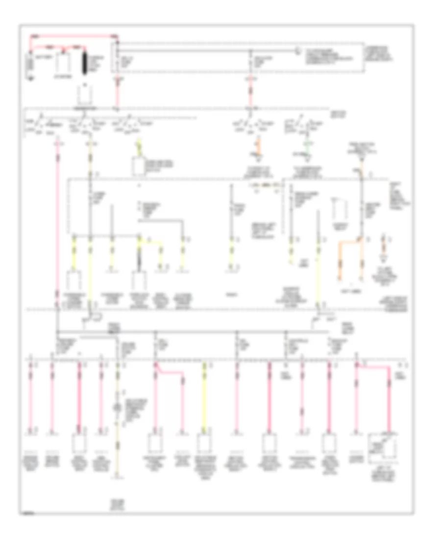
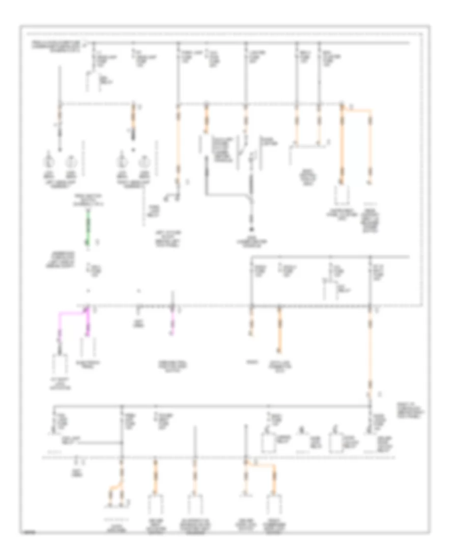
Power Distribution Wiring Diagram (3 of 4) for Saturn L300 2005
List of elements for Power Distribution Wiring Diagram (3 of 4) for Saturn L300 2005:
- (not used)
- A nca
- A/c fuse 10a
- A/c relay
- A/t shift lock actuator
- Audio amplifier
- Aux pwr fuse 20a
- Auxiliary power outlet (under center console)
- Bcm 2 fuse 10a
- Bcm cluster fuse 15a
- Body control module (bcm)
- Body fuse 10a
- C11
- C12
- Cd/dlc fuse 15a
- Cigar lighter
- Data link connector (dlc)
- Door lock relay
- Door locks fuse 15a
- Door unlock relay
- Driver door lock switch
- Driver door unlock relay
- Driver seat adjuster switch
- Drl relay
- E11
- Electronic prndl
- Evaporative emission (evap) canister vent solenoid
- F10
- F12
- Fog lamp fuse 10a
- Fog lamp relay
- From hvac blower fuse g (underhood fuse block) (diagram 2 of 4)
- From ignition switch (diagram 1 of 4)
- Front passenger door lock switch
- G305 (under center console)
- High beam
- Ign 0 fuse 10a
- Instrument panel cluster (ipc)
- Left headlamp assembly
- Left i/p fuse block (behind left kick panel)
- Lighter fuse 20a
- Low beam
- Lt headlamp fuse 10a
- Mirror relay
- Nca
- Park lamp fuse 10a
- Park lamp relay
- Park/neutral position (pnp) switch
- Power seat fuse 20a
- Prem amp fuse 15a
- Radio
- Radio fuse 10a
- Rear compart- ment lid release/ dimmer switch
- Right headlamp assembly
- Right i/p fuse block (behind right kick panel)
- Rt headlamp fuse 10a
- Rt ip batt fuse 30a
- Underhood fuse block (left side of engine compt)
Power Distribution Wiring Diagram (4 of 4) for Saturn L300 2005
List of elements for Power Distribution Wiring Diagram (4 of 4) for Saturn L300 2005:
- (not used)
- A11
- A12
- B12
- C12
- Defog fuse 10a
- E11
- E12
- F12
- From hvac blower fuse (diagram 2 of 4)
- From left i/p fuse block (diagram 2 of 4)
- From right i/p fuse block (diagram 1 of 4)
- H12
- Hvac control module
- Ign 3 fuse 10a
- Ign3 relay
- K11
- K12
- Left heated seat/fog lamp switch connector
- Left i/p fuse block (behind left kick panel)
- Mirror relay
- Rear defog relay
- Rear defogger grid
- Red
- Right heated seat/traction switch
- Right i/p fuse block (behind right kick panel)
- Tan
POWER DOOR LOCKS
Power Door Locks Wiring Diagram for Saturn L300 2005
List of elements for Power Door Locks Wiring Diagram for Saturn L300 2005:
- (behind right kick panel) right i/p fuse block
- (not used)
- A12
- Battery
- Bcm 2 fuse 10a
- Bcm/ cluster fuse 15a
- Body control module (bcm) (mounted to top of glove box)
- Body fuse 10a
- C1 d9
- C2 a2
- C3 c2
- Decklid ajar in
- Dimmer/ rear compartment lid release switch
- Door lock relay
- Door lock rly ctrl
- Door locks fuse 15a
- Door unlock relay
- Driver door jamb switch
- Driver door lock actuator (at rear of driver door)
- Driver door lock switch
- Driver door unlock relay
- Driver unlock rly ctrl
- F12
- Front passenger door lock actuator (at rear of front passenger door)
- Front passenger door lock switch
- G191
- G300 (under center console)
- G401
- Ground
- Ground distribution system
- Hot at all times
- Interior lights system
- Left front jamb sw in
- Left i/p fuse block (behind left kick panel)
- Left rear door jamb switch (at left "b" pillar)
- Left rear door lock actuator
- Lock
- Lock sw in
- Other dr unlk rly ctrl
- Other jamb sw in
- Power distribution system
- Rear compartment lid ajar/release actuator (at center rear of rear compartment lid)
- Release sw in
- Right front door jamb switch
- Right i/p fuse block (behind right kick panel)
- Right rear door jamb switch (at right "b" pillar)
- Right rear door lock actuator
- Sp191 (at left side of engine compt, near strut tower)
- Sp401 (at left rear of vehicle, near left taillight assembly)
- Tan
- Trunk release ctrl
- Trunk/liftgate
- Underhood fuse block (left side of engine compt)
- Unlock
- Unlock sw in
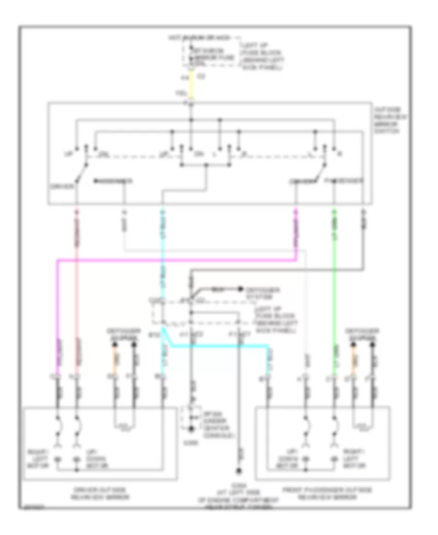
POWER MIRRORS
Power Mirrors Wiring Diagram for Saturn L300 2005
List of elements for Power Mirrors Wiring Diagram for Saturn L300 2005:
- B12
- Btsi/bcm mirror fuse 10a
- C1 f1
- C12
- C2 a1
- Defogger system
- Driver
- Driver outside rearview mirror
- Front passenger outside rearview mirror
- G300
- G304 (at left side of engine compartment near strut tower)
- Hot in run or acc
- Left i/p fuse block (behind left kick panel)
- Nca
- Outside rearview mirror switch
- Passenger
- Right/ left motor
- Sp300 (under center console)
- Up/ down motor
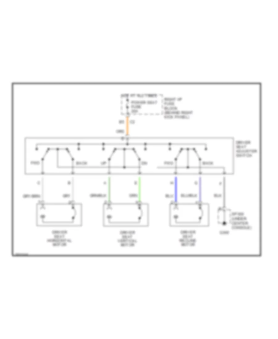
POWER SEATS
Power Seat Wiring Diagram for Saturn L300 2005
List of elements for Power Seat Wiring Diagram for Saturn L300 2005:
- Back
- Driver seat adjuster switch
- Driver seat horizontal motor
- Driver seat recline motor
- Driver seat vertical motor
- Fwd
- G300
- Hot at all times
- Power seat fuse 20a
- Right i/p fuse block (behind right kick panel)
- Sp300 (under center console)
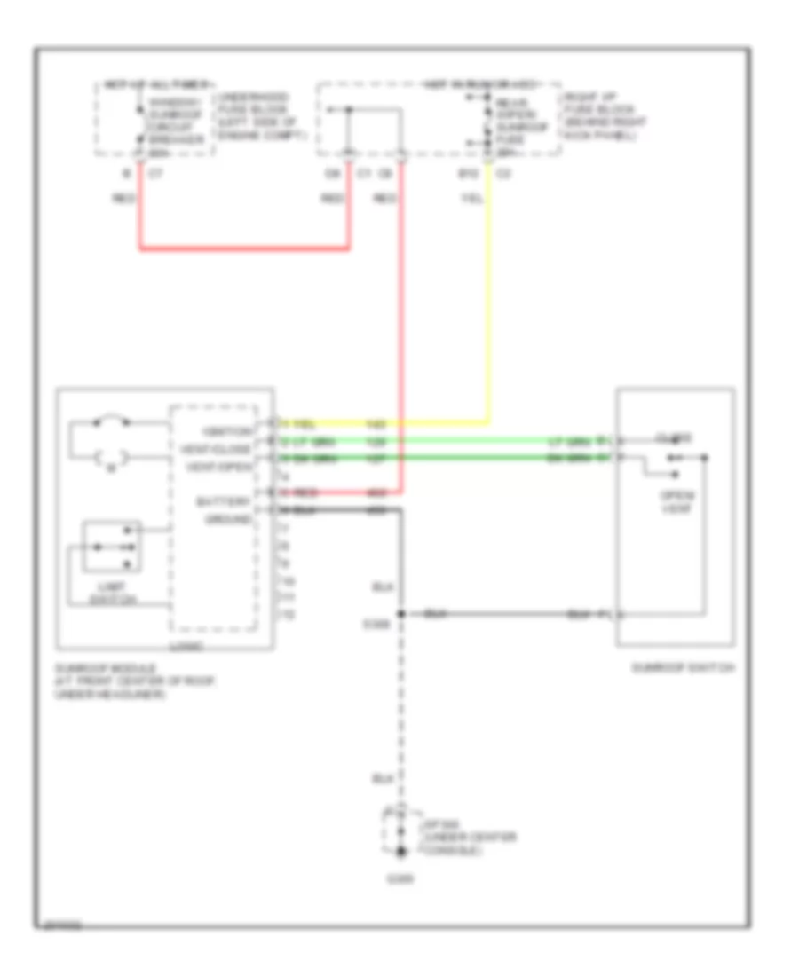
POWER TOP/SUNROOF
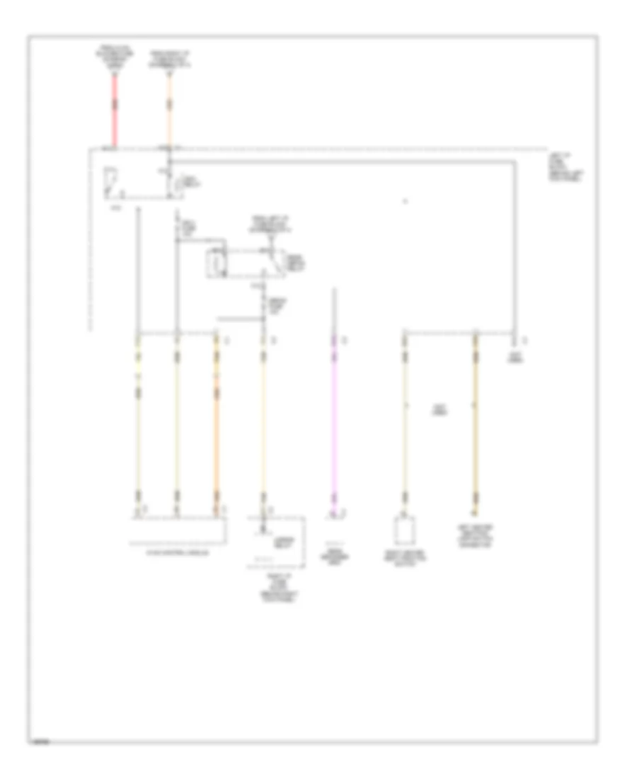
Power Top/Sunroof Wiring Diagram for Saturn L300 2005
List of elements for Power Top/Sunroof Wiring Diagram for Saturn L300 2005:
- B12
- Battery
- Close
- G300
- Ground
- Hot at all times
- Hot in run or acc
- Ignition
- Limit switch
- Logic
- Open/ vent
- Rear wiper/ sunroof fuse 20a
- Red
- Right i/p fuse block (behind right kick panel)
- S308
- Sp300 (under center console)
- Sunroof module (at front center of roof, under headliner)
- Sunroof switch
- Underhood fuse block (left side of engine compt)
- Vent/close
- Vent/open
- Window/ sunroof circuit breaker 30a
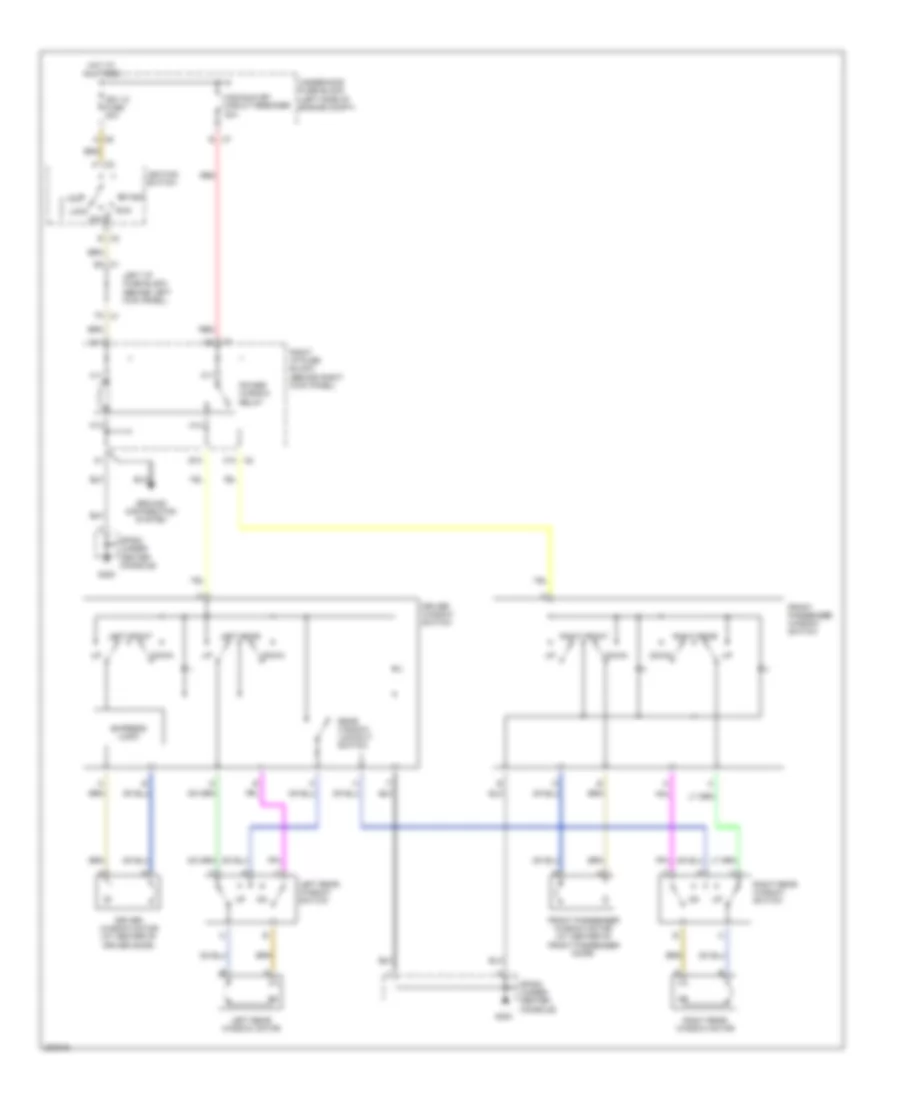
POWER WINDOWS
Power Windows Wiring Diagram for Saturn L300 2005
List of elements for Power Windows Wiring Diagram for Saturn L300 2005:
- Acc
- B10
- C10
- D11
- Down
- Driver window motor (at center of driver door)
- Driver window switch
- Express logic
- Front passenger window motor (at center of front passenger door)
- Front passenger window switch
- G300
- Ground distribution system
- H11
- H12
- Hot at all times
- Ign 1/2 fuse 30a
- Ignition switch
- K11
- K12
- Left front
- Left i/p fuse block (behind left kick panel)
- Left rear
- Left rear window motor
- Left rear window switch
- Lock
- Off
- Power window relay
- Rear window lockout switch
- Red
- Right front
- Right i/p fuse block (behind right kick panel)
- Right rear
- Right rear window motor
- Right rear window switch
- Run
- Sp300 (under center console)
- Start
- Underhood fuse block (left side of engine compt)
- Wdo/sun rf/ circuit breaker 30a
RADIO
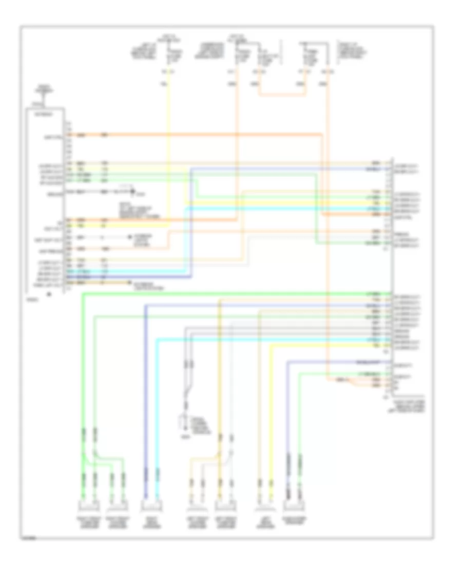
Radio Wiring Diagram for Saturn L300 2005
List of elements for Radio Wiring Diagram for Saturn L300 2005:
- A10
- A11
- A12
- Acc volt
- Amp ctrl
- Amp pre sig
- Antenna
- Audio amplifier (behind upper left side of dash)
- B10
- B11
- B12
- C11
- Coax
- Exterior lights system
- G191
- G300
- Ground
- Hot at all times
- Hot in run or acc
- I/p batt rt fuse 30a
- Inst sup volt
- Interior lights system
- Left front tweeter speaker
- Left front woofer speaker
- Left i/p fuse block (behind left kick panel)
- Left rear speaker
- Lf spk out +
- Lf spk out -
- Lf spkr out+
- Lf spkr out-
- Lr spk out+
- Lr spk out-
- Lr spkr out+
- Lr spkr out-
- Nca
- Park lmp volt
- Pre sig
- Prem amp fuse 15a
- Radio
- Radio antenna
- Radio fuse 10a
- Rf aud sig+
- Rf aud sig-
- Rf spkr out+
- Rf spkr out-
- Right front tweeter speaker
- Right front woofer speaker
- Right i/p fuse block (behind right kick panel)
- Right rear speaker
- Rr spk out +
- Rr spk out -
- Rr spk out+
- Rr spkr out+
- Rr spkr out-
- Sp191 (at left side of engine compt, near strut tower)
- Sp300 (under center console)
- Sub out+
- Sub out-
- Subwoofer speaker
- Tan
- Underhood fuse block (left side of engine compt)
SHIFT INTERLOCK
Shift Interlock Wiring Diagram for Saturn L300 2005
List of elements for Shift Interlock Wiring Diagram for Saturn L300 2005:
- A/t shiftlock control solenoid
- A10
- A12
- Acc voltage
- Automatic transmission shiftlock actuator
- B1 btsi relay ctrl
- B11
- B12
- Body control module (bcm) (mounted to top of glove box)
- Brake fuse 15a
- Btsi/bcm/ mirror fuse 10a
- Can high
- Can low
- E11
- Electronic prndl module
- Engine control module (ecm) (on top right rear of engine)
- F10
- F11
- G304 (at left side of engine compt, near strut tower)
- Gnd
- Hot at all times
- Hot in acc run or start
- Hot in run or acc
- Ign 0 fuse 10a
- Ignition lock cylinder control switch
- Ignition lock cylinder solenoid (at top right of steering column)
- Left i/p fuse block (behind left kick panel)
- Park neutral position (pnp) switch (at top of transmission)
- Power distribution system
- Sig a
- Sig b
- Sig c
- Sig p
- Signal a
- Signal b
- Signal c
- Signal p
- Stop lamp switch (on brake pedal bracket)
- Stop sw sig
- Tan
- Transmission control module (tcm) (right side of engine compartment)
- Underhood fuse block (left side of engine compartment)
- Underhood fuse block (left side of engine compt)
STARTING/CHARGING
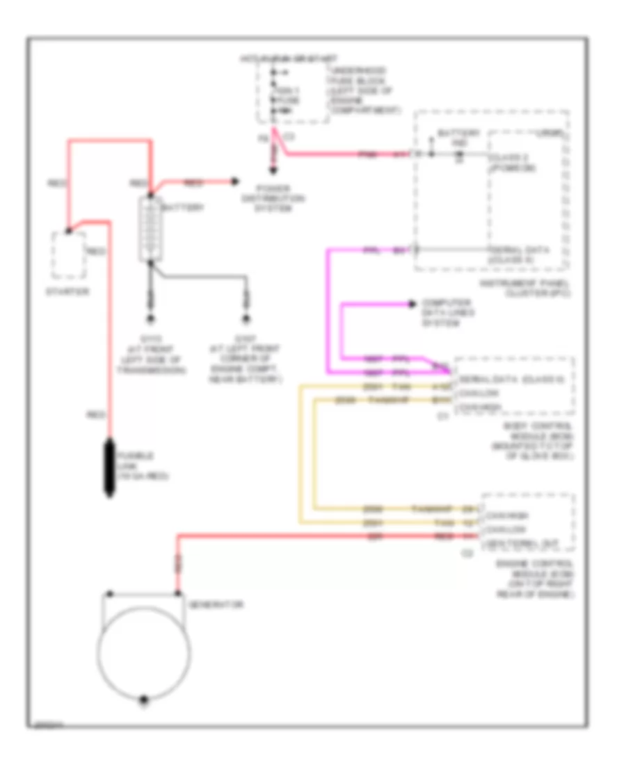
Charging Wiring Diagram for Saturn L300 2005
List of elements for Charging Wiring Diagram for Saturn L300 2005:
- (class ii)
- A12
- B10
- B11
- Battery
- Battery ind
- Body control module (bcm) (mounted to top of glove box)
- Can high
- Can low
- Class 2 (pcm/ecm)
- Computer data lines system
- Engine control module (ecm) (on top right rear of engine)
- F8 pnk
- Fusible link (10 ga-red)
- G107 (at left front corner of engine compt, near battery)
- G113 (at front left side of transmission)
- Gen term l out
- Generator
- Hot in run or start
- Ign 1 fuse 10a
- Instrument panel cluster (ipc)
- Logic
- Pnk
- Power distribution system
- Red
- Serial data
- Serial data (class ii)
- Starter
- Tan
- Underhood fuse block (left side of engine compartment)
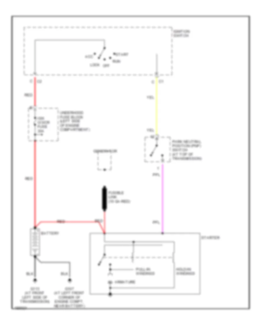
Starting Wiring Diagram for Saturn L300 2005
List of elements for Starting Wiring Diagram for Saturn L300 2005:
- Acc
- Armature m
- Battery
- C1 c
- Fusible link (10 ga-red)
- G107 (at left front corner of engine compt, near battery)
- G113 (at front left side of transmission)
- Generator
- Hold-in windings
- Ign o/3/cr fuse 30a
- Ignition switch
- Lock off
- Park neutral position (pnp) switch (at top of transmission)
- Pull-in windings
- Red
- Run
- Start
- Starter
- Underhood fuse block (left side of engine compartment)
SUPPLEMENTAL RESTRAINTS
Supplemental Restraints Wiring Diagram for Saturn L300 2005
List of elements for Supplemental Restraints Wiring Diagram for Saturn L300 2005:
- (lower left side of dash) data link connector (dlc)
- A10
- A11
- A12
- A13
- A14
- A15
- A16
- A17
- A18
- Air bag ind
- B tan
- B10
- Body control module (bcm) (mounted to top of glove box)
- D10
- Driver seat belt switch
- G303 (under center console)
- Ground
- Hot in run or start
- I/p cluster
- Ign 1
- Ign 1 fuse 10a
- Inflatable restraint i/p module (behind right side of dash)
- Inflatable restraint sensing & diagnostic module (sdm) (at center of vehicle, under center console)
- Inflatable restraint steering wheel module (in steering wheel)
- Inflatable restraint steering wheel module coil (under steering wheel)
- Left inflatable restraint side impact module (behind left "c" pillar trim)
- Left inflatable restraint side impact sensor (at left "b" pillar)
- Left satellite in
- Left satellite out
- Left side mod hi
- Left side mod lo
- Logic
- Module hi
- Module lo
- Nca
- Pnk
- Power distribution system
- Return
- Right inflatable restraint side impact module (behind right "c" pillar trim)
- Right inflatable restraint side impact sensor (sis) (at right "b" pillar)
- Right satellite in
- Right satellite out
- Right side mod hi
- Right side mod lo
- Serial data class 2
- Shorting bar
- Switch hi
- Switch lo
- Tan
- Underhood fuse block (left side of engine compartment)
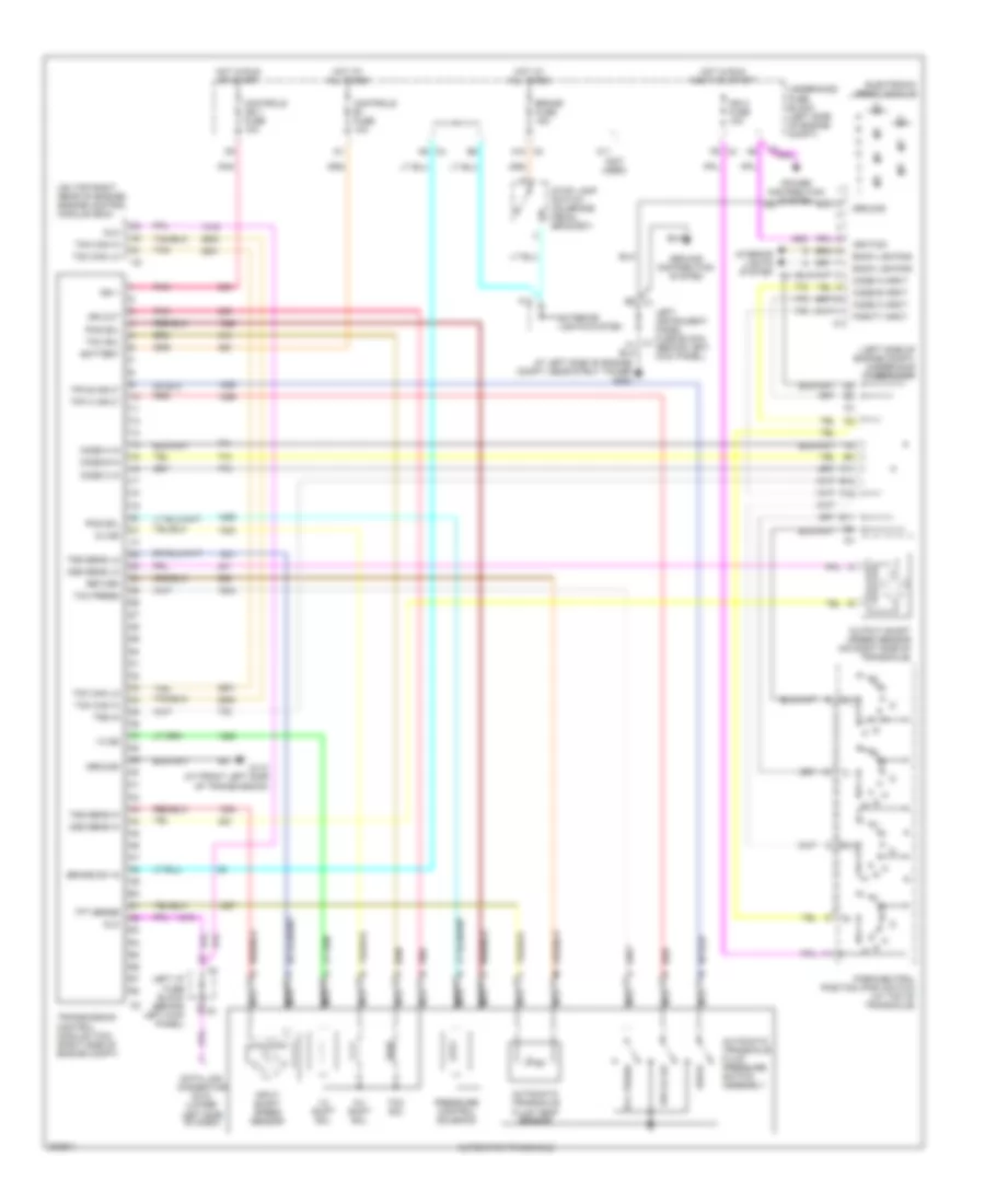
TRANSMISSION
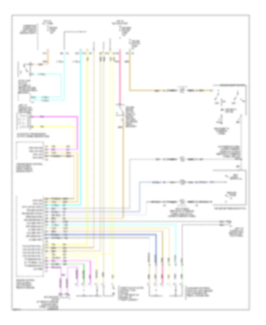
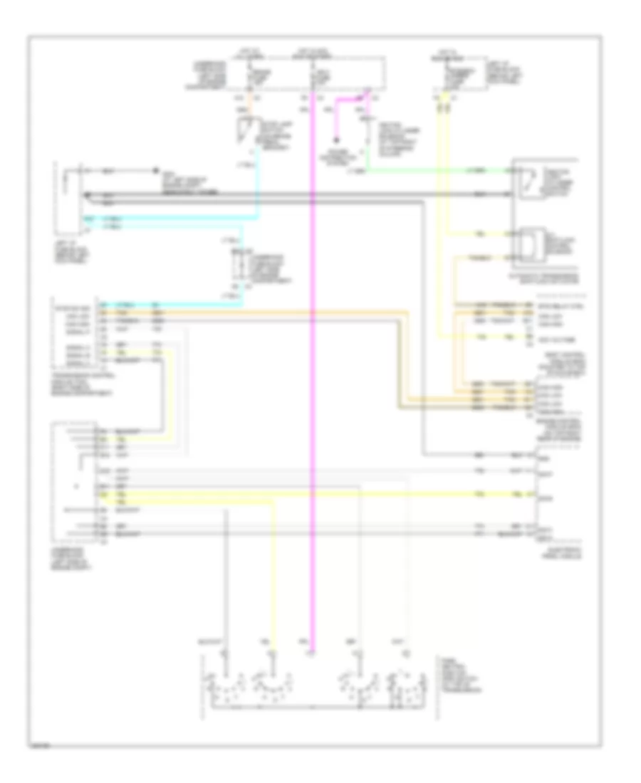
A/T Wiring Diagram for Saturn L300 2005
List of elements for A/T Wiring Diagram for Saturn L300 2005:
- (left side of engine compt) underhood fuse block
- (not used)
- (on top right rear of engine) engine control module (ecm)
- 1-2 shift sol
- 1-2 ss
- 2-3 shift sol
- 2-3 ss
- A10 c3
- A12
- A9 c4
- At left side of engine compt, near strut tower g304
- Automatic transaxle
- Automatic transaxle fluid pressure switch assembly
- Automatic transaxle fluid temp sensor
- B12
- B7 c2
- Back lighting
- Battery
- Brake fuse 15a
- Brake sw in
- C11
- Code a in
- Code a input
- Code b in
- Code b input
- Code c in
- Code c input
- Controls b+ fuse 10a
- Controls ign 1 fuse 10a
- Data link connector (dlc) (lower left side of dash)
- Dlc
- Drive
- E11
- E9 c1
- Electronic prndl module
- Exterior lights system
- F10
- F11
- F9 c4
- G110 (at front left side of transmission)
- Ground
- Ground distribution system
- Hot at all times
- Hot in run accy or start
- Hot in run or start
- Ign 0 fuse 10a
- Ign 1
- Ign out
- Ignition
- Input shaft speed sensor
- Interior lights system
- Left i/p fuse block (behind left kick panel)
- Left instrument panel fuse block (behind left kick panel)
- Nca
- Oss sens hi
- Oss sens lo
- Output shaft speed sensor (on right side of transaxle)
- Parity input
- Park/neutral position (pnp) switch (at top of transaxle)
- Pcs sol
- Pnk
- Power distribution system
- Pressure control solenoid
- Red
- Return
- Rev,d1,d2
- Stop lamp switch (on brake pedal bracket)
- Tan
- Tcc press
- Tcc sol
- Tcm can hi
- Tcm can lo
- Tfp b input
- Tfp c input
- Tft sense
- Transmission control module (tcm) (right side of engine compt)
- Trs in
- Tss sens hi
- Tss sens lo
- Underhood fuse block (left side of engine compt)
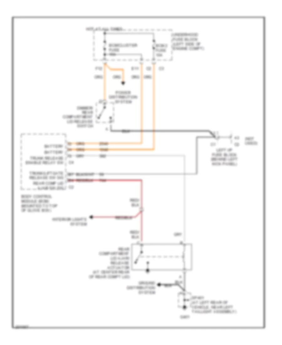
TRUNK, TAILGATE, FUEL DOOR
Trunk Release Wiring Diagram for Saturn L300 2005
List of elements for Trunk Release Wiring Diagram for Saturn L300 2005:
- (not used)
- Battery
- Bcm 2 fuse 10a
- Bcm/cluster fuse 15a
- Body control module (bcm) (mounted to top of glove box)
- Dimmer/ rear compartment lid release switch
- E11
- F12
- G401
- Ground distribution system
- Hot at all times
- Interior lights system
- Left i/p fuse block (behind left kick panel)
- Power distribution system
- Rear comp lid ajar sw sig
- Rear compartment lid ajar/ release actuator (at center rear of rear compt lid)
- Sp401 (at left rear of vehicle, near left taillight assembly)
- Trunk release enable relay sw
- Trunk/liftgate release sw sig
- Underhood fuse block (left side of engine compt)
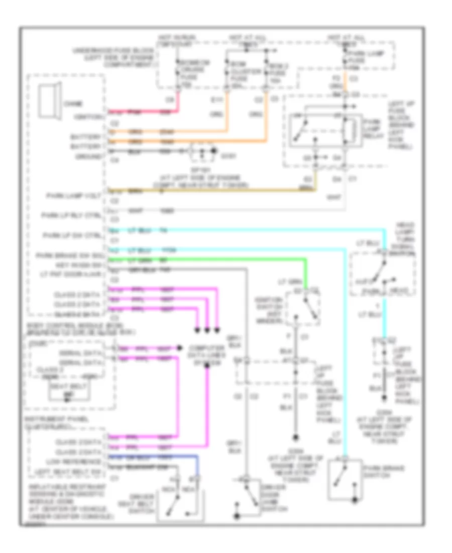
WARNING SYSTEMS
Warning Systems Wiring Diagram for Saturn L300 2005
List of elements for Warning Systems Wiring Diagram for Saturn L300 2005:
- (ign)
- A10
- A11
- A15
- A16
- Auto
- B10
- Battery
- Bcm 2 fuse 10a
- Bcm/ cluster fuse 15a
- Bcm/ecm cruise fuse 10a
- Body control module (bcm) (mounted to top of glove box)
- Chime
- Class 2 (sdm)
- Class 2 data
- Computer data lines system
- Driver door jamb switch
- Driver seat belt switch
- E11
- G191
- G304 (at left side of engine compt, near strut tower)
- Ground
- Head
- Head lamp/ turn signal switch
- Hot at all times
- Hot in run or start
- Ignition
- Ignition switch (key minder)
- Inflatable restraint sensing & diagnostic module (sdm) (at center of vehicle, under center console)
- Instrument panel cluster (ipc)
- Key in ign sw
- Left i/p fuse block (behind left kick panel)
- Left seat belt sw
- Logic
- Low reference
- Lt fnt door ajar
- Nca
- Park
- Park brake sw sig
- Park brake switch
- Park lamp fuse 10a
- Park lamp relay
- Park lamp volt
- Park lp rly ctrl
- Park lp sw ctrl
- Pnk
- Seat belt ind
- Serial data
- Sp191 (at left side of engine compt, near strut tower)
- Underhood fuse block (left side of engine compartment)
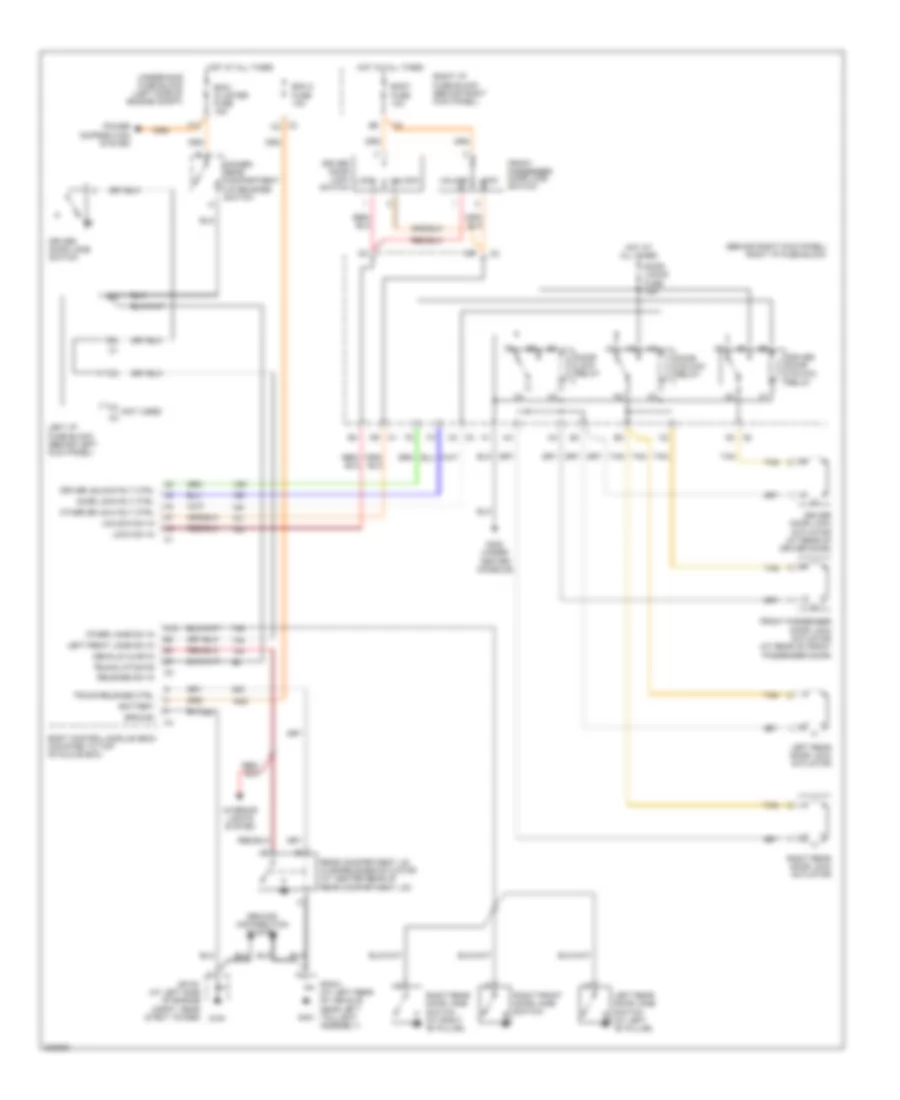
WIPER/WASHER
Wiper/Washer Wiring Diagram for Saturn L300 2005
List of elements for Wiper/Washer Wiring Diagram for Saturn L300 2005:
- A11
- B11
- B12
- Body control module (bcm) (mounted to top of glove box)
- Class 2 (bcm)
- E11
- E12
- F12
- Front washer switch
- Front wiper rly ctrl
- G103
- G11
- G110 (at front left side of transmission)
- G12
- G304 (at left side of engine compt, near strut tower)
- High
- Hot in acc or run
- Hot in run or start
- Ign 1 fuse 10a
- Instrument panel cluster (ipc)
- Int
- Int switch
- Left i/p fuse block (behind left kick panel)
- Logic
- Low
- Low ref
- Mist
- Off
- Pnk
- Power distribution system
- Rear window washer pump ctrl
- Red
- Sp103 (at left front corner of engine compt, near battery)
- Underhood fuse block (left side of engine compt)
- Washer fluid level sig
- Washer fluid low ind
- Washer pump ctrl
- Windshield washer fluid level switch (at left front corner of engine compt)
- Windshield washer fluid pump (at left front corner of engine compt)
- Windshield wiper motor (at left rear of engine compt)
- Windshield wiper/washer switch
- Wiper fuse 25a
- Wiper relay
- Wiper sw pulse/ delay sig
- Wiper sw sig 2

 Čeština
 Dansk
Dansk Deutsch
 Ελληνικά
 English
 English
 Español
 Suomi
Suomi Français
 Français
 עברית
עברית Hrvatski
 Magyar
 日本語
日本語 한국어
한국어 Nederlands
 Polski
 Português
 Português
 Română
 Русский
 Slovenčina
 Slovenščina
 Svenska
 Türkçe
 中文 (中国)