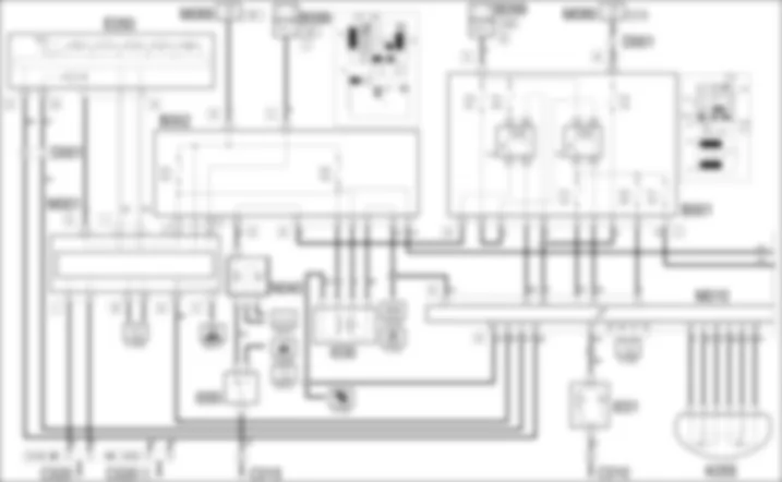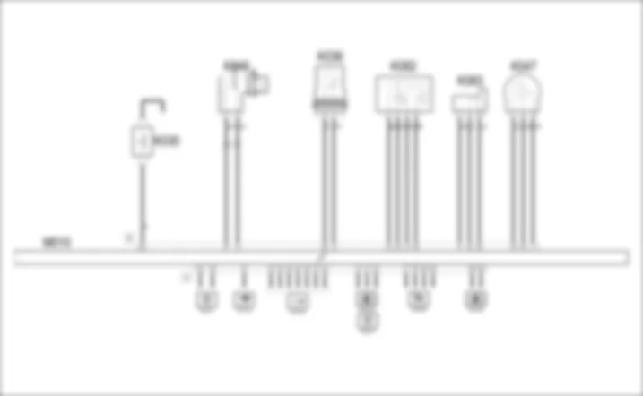

WIRING DIAGRAM - DIESEL ENGINES ELECTRONIC MANAGEMENT - Alfa Romeo 159 2.4 JTD 20V Da 01/06
COMPONENTS - DIESEL ENGINES ELECTRONIC MANAGEMENT - Alfa Romeo 159 2.4 JTD 20V Da 01/06
| Component code | Description | Reference to the operation |
| A040 | HEATER PLUGS | |
| B001 | JUNCTION UNIT | |
| B002 | JUNCTION UNIT UNDER DASHBOARD | |
| B099 | MAXIFUSE BOX ON BATTERY | |
| C010 | LEFT FRONT EARTH | - |
| C015 | DASHBOARD EARTH, DRIVER'S SIDE | - |
| C020 | PASSENGER SIDE DASHBOARD EARTH | - |
| C040 | ENGINE EARTH | - |
| D001 | FRONT/DASHBOARD COUPLING | - |
| D004 | FRONT/ENGINE COUPLING | - |
| E050 | INSTRUMENT PANEL | |
| I030 | BRAKE PEDAL SWITCH | |
| I031 | CLUTCH PEDAL SWITCH | |
| I050 | INERTIA SWITCH | |
| K030 | LOW ENGINE OIL PRESSURE SENSOR (SWITCH) | |
| K036 | ENGINE COOLANT TEMPERATURE SENSOR/SENDER UNIT | |
| K041 | AIR FLOW METER | |
| K046 | RPM SENSOR | |
| K047 | TIMING SENSOR | |
| K055 | ACCELERATOR PEDAL POTENTIOMETER | |
| K082 | SUPERCHARGING SENSOR | |
| K083 | FUEL PRESSURE SENSOR | |
| K101 | FUEL TEMPERATURE AND WATER IN FUEL FILTER SENSOR | |
| L030 | EGR SOLENOID VALVE | |
| L036 | TURBINE VARIABLE GEOMETRY CONTROL SOLENOID VALVE | |
| L064 | FLOW MODIFYING SOLENOID VALVE | |
| M001 | BODY COMPUTER | |
| M010 | ENGINE MANAGEMENT ECU | |
| M015 | PLUG PREHEATING CONTROL UNIT | |
| M089 | STEERING LOCK CONTROL UNIT (NBS) | |
| N040 | FUEL PUMP AND LEVEL GAUGE | |
| N070 | INJECTOR | |
| N075 | THROTTLE BODY ACTUATOR | |
| N077 | FUEL PRESSURE REGULATOR | |
| N087 | FUEL PRESSURE REGULATOR ON RAIL |
COMPONENT LOCATION - DIESEL ENGINES ELECTRONIC MANAGEMENT - Alfa Romeo 159 2.4 JTD 20V Da 01/06
| Component code | Description | Reference to the operation |
| A040 | HEATER PLUGS | |
| B001 | JUNCTION UNIT | |
| B002 | JUNCTION UNIT UNDER DASHBOARD | |
| B099 | MAXIFUSE BOX ON BATTERY | |
| C010 | LEFT FRONT EARTH | - |
| C015 | DASHBOARD EARTH, DRIVER'S SIDE | - |
| C020 | PASSENGER SIDE DASHBOARD EARTH | - |
| C040 | ENGINE EARTH | - |
| D001 | FRONT/DASHBOARD COUPLING | - |
| D004 | FRONT/ENGINE COUPLING | - |
| E050 | INSTRUMENT PANEL | |
| I030 | BRAKE PEDAL SWITCH | |
| I031 | CLUTCH PEDAL SWITCH | |
| I050 | INERTIA SWITCH | |
| K030 | LOW ENGINE OIL PRESSURE SENSOR (SWITCH) | |
| K036 | ENGINE COOLANT TEMPERATURE SENSOR/SENDER UNIT | |
| K041 | AIR FLOW METER | |
| K046 | RPM SENSOR | |
| K047 | TIMING SENSOR | |
| K055 | ACCELERATOR PEDAL POTENTIOMETER | |
| K082 | SUPERCHARGING SENSOR | |
| K083 | FUEL PRESSURE SENSOR | |
| K101 | FUEL TEMPERATURE AND WATER IN FUEL FILTER SENSOR | |
| L030 | EGR SOLENOID VALVE | |
| L036 | TURBINE VARIABLE GEOMETRY CONTROL SOLENOID VALVE | |
| L064 | FLOW MODIFYING SOLENOID VALVE | |
| M001 | BODY COMPUTER | |
| M010 | ENGINE MANAGEMENT ECU | |
| M015 | PLUG PREHEATING CONTROL UNIT | |
| M089 | STEERING LOCK CONTROL UNIT (NBS) | |
| N040 | FUEL PUMP AND LEVEL GAUGE | |
| N070 | INJECTOR | |
| N075 | THROTTLE BODY ACTUATOR | |
| N077 | FUEL PRESSURE REGULATOR | |
| N087 | FUEL PRESSURE REGULATOR ON RAIL |
DESCRIPTION - DIESEL ENGINES ELECTRONIC MANAGEMENT - Alfa Romeo 159 2.4 JTD 20V Da 01/06
An electronic control system supervises and governs all engine parameters to optimise performance and fuel consumption by means of a real-time response to different service conditions.Diesel engines are equipped with a COMMON RAIL type injection system.This features the use of an electronically controlled high injection pressure. The supply of fuel, known as the pilot injection, is optimized by the electronic control unit by means of the injector rather than managed by the pump.In this 4 valve per cylinder version, the common rail injection system uses Multijet technology: i.e. during each engine stroke, it carries out more than the two injections normally used: it performs two pre-injections (before the piston is at top dead centre), one main and two post-injections.This solution improves fuel consumption, noise levels and performance because it allows better control of temperature in the combustion chamber by lowering the maximum value and extending the optimum combustion area.The throttle body is also controlled electronically by the control unit: the throttle opening is calculated in accordance with a specific logic inside the engine management control unit.Depending on the signals received from numerous sensors, the control unit controls the injectors connected to it managing the following systems:- fuel supply;- air supply;- heater plugs;- accelerator pedal;- engine cooling;- particle filter management.In order to conform with the most recent pollution control standards (EURO 4) the most recent version of electronic management has been adopted which includes new components (injectors, pressure regulator and high pressure pump on the rail, digital flow meter) and swirl solenoid valves and a DPF particle filter has been adopted.A throttle that regulates the flow of air is modulated to improve the air fuel mixture in the combustion chamber: with the throttle open the power supply is maximum; closing the throttle gradually reduces the load, the engine rpm and also theThe DPF particle filter (Diesel Particulate Filter) is a mechanical filter, inserted in the exhaust pipes which traps the carbon particles present in the exhaust gases on diesel engines. The filter makes it possible to almost totally eliminate the emission of carbon particles in line with current legislation.For more details,The system is also controlled by dedicated relays in the engine compartment control unit. Lines supplying the control unit and various system components (sensors and actuators) are protected by dedicated fuses that are also located inside the engine compartment.
FUNCTIONAL DESCRIPTION - DIESEL ENGINES ELECTRONIC MANAGEMENT - Alfa Romeo 159 2.4 JTD 20V Da 01/06
Engine management control unit M10 controls and governs the entire electronic ignition and injection system.The ignition-operated power supply (15/54) arrives via a line protected by fuse F16 of the engine compartment junction unit B1 at pin 28 of connector A of M10 .Pins 2, 4 and 6 of connector A of M10 are earthed.Main injection relay T9 of B1 controls the entire system: it is energized by an earth signal from pin 72 of connector A of engine control unit M10 and then forwards a power supply:- to pin 1 of connector A of the control unit, via the line of fuse F17 of B1 ;- to pin 5 of connector A of the control unit, via the line of fuse F22 of B1 ;- to the solenoid valves L30, L36, L64, to the throttle N75, to the control unit M15, via the line from fuse F11 of B1.The fuel pump relay T10 of B1 is supplied by the line for fuse F21 of B1. This is energized by a command signal (earth) from pin 91 of connector A of control unit M10 and supplies power to fuel pump N40 , which is earthed via inertia switch I50 , that cuts off the circuit in the case of impact and thus prevents dangerous flows of fuel.Control unit M15 that manages the preheating of the heater plugs A40 is supplied directly - connector A - from the battery via a line protected by the CPR MAXI FUSE of B99.This is supplied at connector C - from the line of fuse F11 of B1 , and exchanges command and control signals with pins 52 and 93 of connector A of M10, which controls the timing. Connector B is connected to the heater A40 .The engine management control unit M10 receives signals from the various sensors thereby keeping all the engine operating parameters under control.Rpm sensor K46 supplies, via a frequency signal exchanged with pins 12 and 27 of connector B of control unit M10 , information on engine speed.Timing sensor K47 is supplied from pin 11 of connector B of M10 . It receives a reference earath from pin 20 of connector B of control unit M10 and on the way to this, a frequency signal corresponding to the phase at pin 50 of connector B.Engine temperature sensor K36 receives a reference earth from pin 41 of connector B of control unit M10 , and sends a signal proportional to engine coolant temperature to pin 58 of connector B .The air flow meter K41 - receiving an ignition-controlled supply (INT) from fuse F35 of junction unit B2 - receives a reference earth from pin 44 of connector B of M10 and sends pin 42 of connector A a signal proportional to the air flow rate.An air temperature sensor inside K41 also sends an air temperature signal to pin 37 of connector B of M10 .The accelerator pedal K55 has two built in potentiometers (one main one and one safety one).The former receives power and earth signals from pins 30 and 45 of connector A of M10 and sends a corresponding signal to pin 9.The latter receives power and earth signals from pins 46 and 8 of connector A of M10 and sends a signal to pin 31.The fuel temperature sensor, incorporated in the diesel filter K101, detects the temperature of the incoming diesel fuel. It receives a reference earth from pin 10 of connector A of M10 and sends a fuel temperature signal to pin 11.The supercharging sensor K82 measures the pressure and the temperature in the intake chamber, downstream of the turbocharger. It is supplied by pin 13 of connector B of M10 and receives a reference earth from pin 23 of connector B.The signal corresponding to the pressure value is sent to pin 40 of control unit connector B. An air temperature sensor, housed in K82, sends a signal to pin 53 of connector B of M10.Fuel pressure sensor K83 supplies the injection control unit with a feedback signal to modulate injection pressure and duration.It receives power and a reference earth from pins 28 and 8 of connector B of M10 ; it then sends a pressure signal to pin 43.The fuel pressure regulator on the pump N77 controls the high pressure produced by the actual pump; the two control signals come from pins 19 and 49 of connector B of control unit M10.The fuel pressure regulator on the rail N78 is responsible for keeping the value of the fuel pressure in the actual rail constant; the two control signals arrive from pins 4 and 34 of connector B of control unit M10.The EGR solenoid L30 controls exhaust gas recirculation. It is supplied by a line from fuse F11 of B1 , and is controlled by a signal from pin 60 of connector B of M10 .The turbine variable geometry solenoid valve L36 regulates the operation of the turbine depending on the engine load: it is supplied by the line for fuse F11 of B1 and is controlled by a signal from pin 7 of connector A of M10.The swirl solenoid valve L64 ensures the optimum air fuel mixture; it is supplied by the line for fuse F11 of B1 and is operated by a signal for pin 45 of connector B of M10; the solenoid valve control signals leave from pins 6 and 35 of connector B of M10.The throttle body actuator N75 controls the opening of the throttle by means of a stepping motor; the motor receives a power supply from the line for fuse F11 of B1 and is controlled by a signal for pin 59 of connector B of M10; the control signals leave from pins 39 and 52 of connector B of M10.The engine management control unit sends the command to the injectors N70 from pins 16-47, 2-31, 1-46, 17-33 and 18-48 of connector B of M10 for cylinders 1, 2, 3, 4 and 5 respectively.Pin 17 of connector A of M10 receives the N.A. signal coming from the brake lights switch I30 with an ignition-controlled supply (INT) from fuse F37 of junction unit B2.Pin 80 of connector A of M10 receives the N.C. signal coming from the brake lights switch I30 with an ignition-controlled supply (INT) from fuse F35 of junction unit B2.Pin 79 of connector A of M10 receives the signal coming from the clutch switch I31.The control unit M10 receives - at pin 56 of connector B - a signal from the minimum engine oil pressure sensor K30The water in the diesel filter sensor - integrated in filter K101 - receives an ignition-operated supply (INT) from fuse F35 of junction unit B2 and sends the corresponding signal to pin 74 of connector A of M10.Control unit M10 is then connected via the CAN - pins 83-84 and 61-64 of connector A of M10 - to the Body Computer M1 and to the other network nodes: it sends information through this connection on:- engine coolant temperature, which is sent to instrument panel E50 and from there to the centre instrument console E20, that controls the gauge and warning light;- engine rpm, which is sent to the instrument panel E50 rev counter;- minimum engine oil pressure, which is sent to the instrument panel E50 which manages the warning light;- heater plugs pre-heating, which is sent to instrument panel E50 that controls the warning light;- water in the diesel filter, which is sent to instrument panel E50 that controls the display;It receives a speedometer signal via the CAN network that is generated by the ABS control unit M50.The signal for the turbocharger pressure is sent separately from pin 26 of connector A of M10 to the instrument panel E50 and from there to the centre instrument console E20.The autodiagnostic system for the control unit M10 also produces a signal - which leaves pin 71 of connector A - which is connected directly to the EOBD warning light in the instrument panel E50.The autodiagnostic data can be read by connecting to connector C of the Body Computer M1 - pin 7: it receives signals from pin 25 of connector A of control unit M10 via the special diagnostic line.
 Deutsch
 English
 English
 Español
 Français
 Nederlands
 Русский

