AIR CONDITIONING
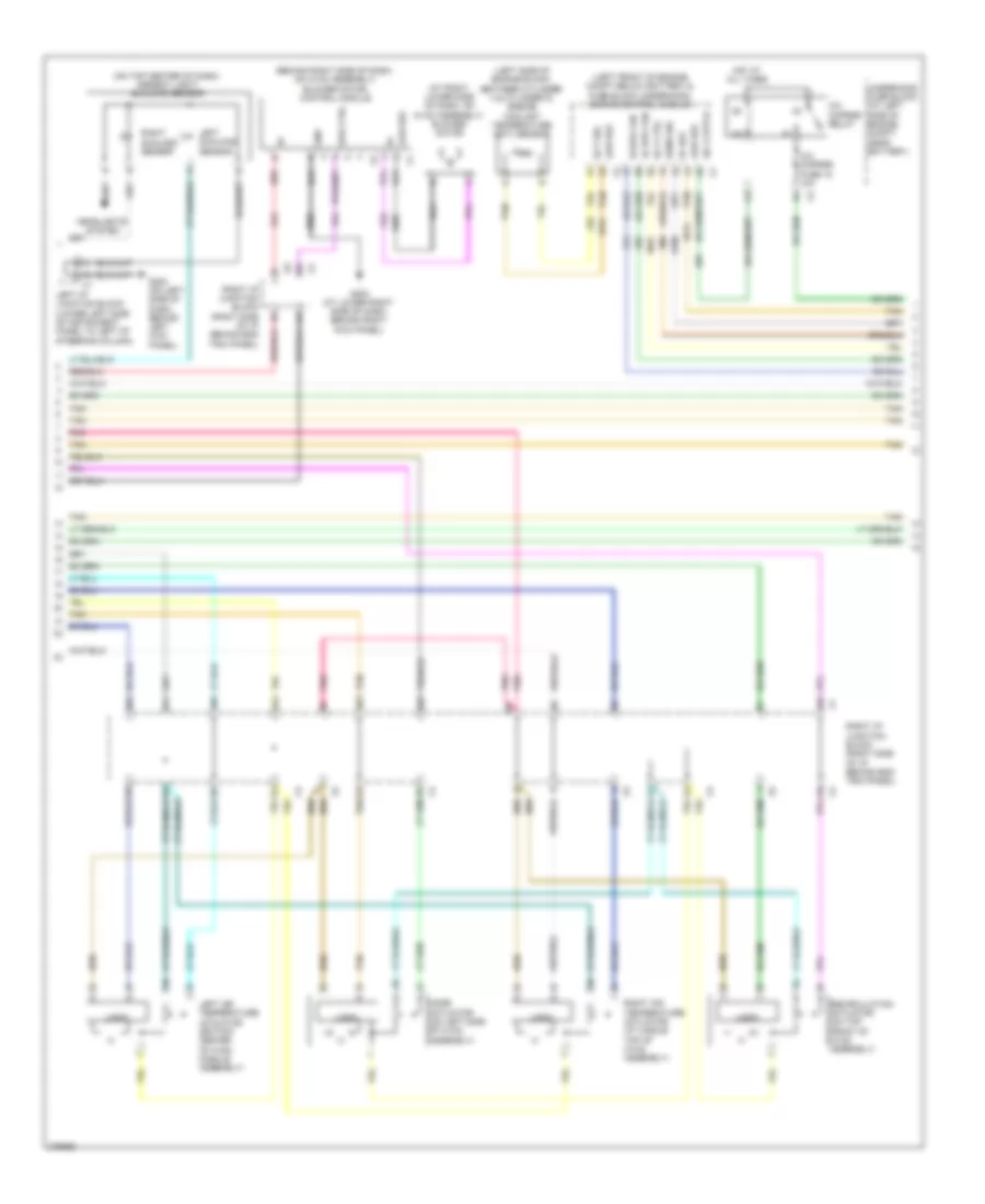
Automatic A/C Wiring Diagram (1 of 3) for Hummer H2 2008

List of elements for Automatic A/C Wiring Diagram (1 of 3) for Hummer H2 2008:
- 5-volt reference
- A/c low pressure switch (on right side of a/c a
- A/c on ind
- A/c on switch
- Accumulator at rear of engine compt)
- Air request ind
- Air request switch
- Assembly ctrl
- Auto switch
- Aux hvac ign fuse 41 10a
- Auxiliary air temperature actuator (right rear of cargo area on the front of auxiliary hvac module)
- Auxiliary blower motor (upper rear of auxiliary hvac module)
- Auxiliary blower motor control module (rear of auxiliary hvac module above blower motor-auxiliary)
- Auxiliary mode actuator (left front of auxiliary hvac module assembly)
- B(+)
- Computer data lines system
- Ctrl
- Door position sig
- Fan down switch
- Fan up switch
- Front defogger ind
- Front defogger switch
- G103 (on front of right cylinder head)
- G200 (on left side of dash, behind left kick panel)
- G203 (at lower right side of dash, behind right kick panel)
- G410 (on passenger side rear of body near d-pillar behind trim panel)
- Gmlan serial data
- Gnd
- Ground
- Hot at all times
- Hot w/ run/crank relay energized
- Hvac batt fuse 33 10a
- Hvac blwr fuse 61 40a
- Hvac control module
- Hvac ign fuse 46 10a
- I/p fuse block (on lower left side of i/p, behind access panel)
- Ig voltage
- J215
- J441
- J442
- J443
- Left i/p junction block (lower left side of instrument panel to left of steering column)
- Left i/p junction block x11 (lower left side of instrument panel to left of steering column)
- Left temperature control
- Lo press sens sig
- Logic
- Logic speed down
- Low reference
- Mode
- Mode door ctrl
- Mode down switch
- Mode up switch
- Motor speed ctrl
- Off switch
- On/ off
- Pnk
- Position sens sig
- Power distribution system
- Rear defogger ind
- Rear defogger switch
- Rear hvac fuse 30a
- Rear seat audio (rsa) control
- Recir door ctrl
- Recir- culation ind
- Recir- culation switch
- Right sw sig
- Right temperature control
- Sens sig
- Serial data
- Speed ctrl
- Speed up
- Sunload sens sig
- Tan
- Temp door ctrl
- Temp down
- Temp sens sig
- Temp up
- Underhood fuse block (at left side of engine compt, near battery)
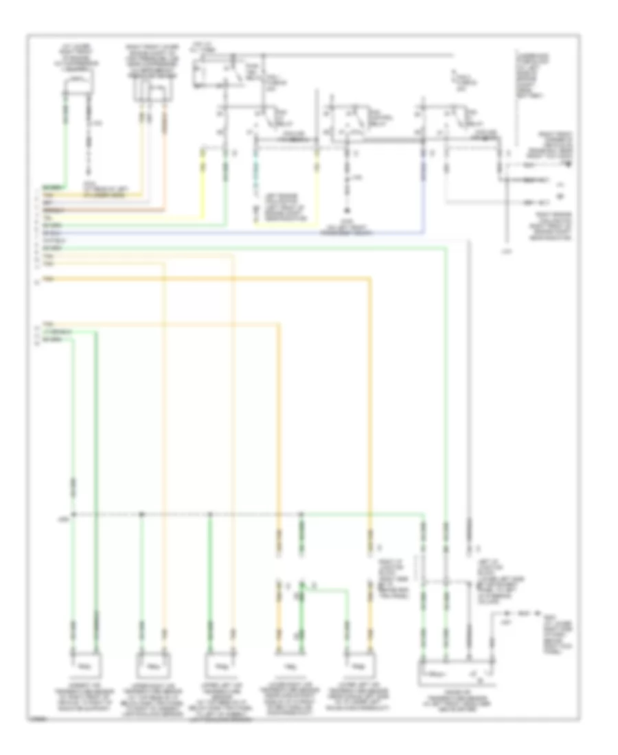
Automatic A/C Wiring Diagram (2 of 3) for Hummer H2 2008
List of elements for Automatic A/C Wiring Diagram (2 of 3) for Hummer H2 2008:
- (at right lower side of dash, on hvac assembly) blower motor
- (behind right side of dash, on hvac assembly) blower motor control module
- (left front of engine compt below battery & fuse block underhood) engine control module
- (left side of engine block, between cylinder 3 & cylinder 5) engine coolant temperature (ect) sensor
- (on top center of dash) ambient light/ sunload sensor
- 4a1
- 4a4
- 4a5
- 4a6
- 4b2
- 4b3
- 4b5
- 4b6
- 5v ref
- A/c clutch
- A/c cmprsr fuse 15 10a
- A/c cmprsr relay
- Ect sig
- G200 (on left side of dash, behind left kick panel)
- G203 (at lower right side of dash, behind right kick panel)
- Gnd
- Headlights system
- Hi spd fan
- Hot at all times
- Left air temperature actuator (bottom center of hvac module assembly)
- Left i/p junction block (lower left side of instrument panel to left of steering column)
- Left sunload sensor
- Lo spd fan
- Logic
- Low ref
- Mode actuator (on left side of hvac assembly)
- Pnk
- Recirculation actuator (on top front of hvac assembly)
- Red
- Right air temperature actuator (at middle top of hvac assembly)
- Right i/p junction block (right side of i/p behind end trim panel)
- Right sunload sensor
- Rly ctrl
- Sens sig
- Spd ctrl
- Tan
- Underhood fuse block (at left side of engine compt, near battery)
Automatic A/C Wiring Diagram (3 of 3) for Hummer H2 2008
List of elements for Automatic A/C Wiring Diagram (3 of 3) for Hummer H2 2008:
- (at lower right front of engine) a/c compressor clutch
- (right front corner of vehicle on frame rail near front tow hook) g101
- (right front lower engine compt on high pressure line near compressor) a/c refrigerant pressure sensor
- 4a2
- 4a3
- 87a
- Ambient air temperature sensor (at right front of vehicle, to right of radiator support)
- Cooling fan diode 1
- Cooling fan diode 2
- Fan 1 fuse 50 40a
- Fan 2 fuse 53 40a
- Fan control relay
- Fan hi relay
- Fan lo relay
- G100 (on left front frame body mount)
- G104 (at rear of left cylinder head)
- G203 (at lower right side of dash, behind right kick panel)
- Hot at all times
- Inside air temperature sensor (in left front headliner above driver)
- J100
- J101
- J102
- J206
- J301
- Left engine cooling fan (left front of engine compt near radiator)
- Left i/p junction block (lower left side of instrument x9 panel to left of steering column)
- Lower left air temperature sensor (near middle left side of i/p under left round discharge duct)
- Lower right air temperature sensor (near middle right side of i/p in front of rectangular discharge duct)
- Pwr/ trn relay
- Right engine cooling fan (right front of engine compt near radiator)
- Right i/p junction block (right side of i/p x4 behind end trim panel)
- Tan
- Underhood fuse block (at left side of engine compt, near battery)
- Upper left air temperature sensor (at top rear of i/p below dash trim panel to left of ambient light/sunload sensor)
- Upper right air temperature sensor (at top rear of i/p below dash trim panel to right of ambient light/sunload sensor)
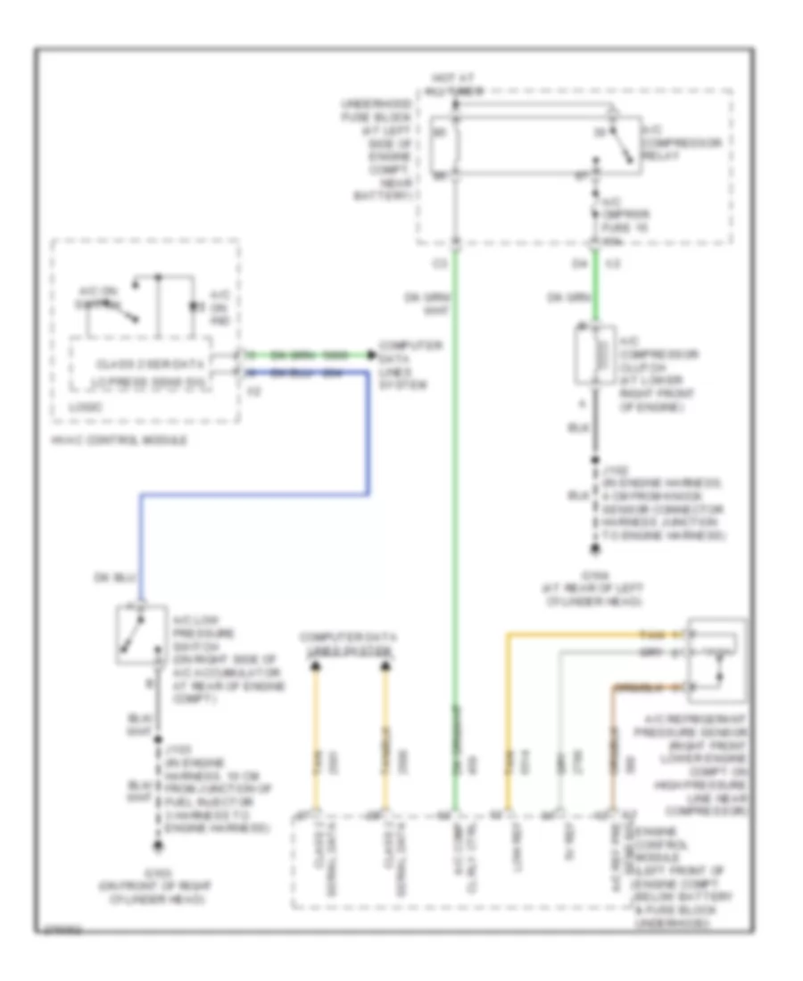
Compressor Wiring Diagram for Hummer H2 2008
List of elements for Compressor Wiring Diagram for Hummer H2 2008:
- 5v ref
- A/c cmprsr fuse 15 10a
- A/c comp
- A/c compressor clutch (at lower right front of engine)
- A/c compressor relay
- A/c low pressure switch (on right side of a/c accumulator at rear of engine compt)
- A/c on ind
- A/c on switch
- A/c ref pre
- A/c refrigerant pressure sensor (right front lower engine compt on high pressure line near compressor)
- Cl rly ctrl
- Class 2
- Class 2 ser data
- Computer data lines system
- G103 (on front of right cylinder head)
- G104 (at rear of left cylinder head)
- Hot at all times
- Hvac control module
- J102 (in engine harness, 4 cm from knock sensor connector harness junction to engine harness)
- J103 (in engine harness, 10 cm from junction of fuel injector 3 harness to engine harness)
- Lo press sens sig
- Logic
- Low ref
- Serial data
- Tan
- Underhood fuse block (at left side of engine compt, near battery)
- X1 sens sig engine control module (left front of engine compt below battery & fuse block underhood)