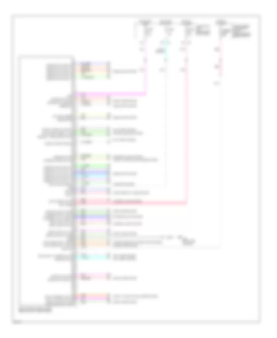
BODY CONTROL MODULES
Body Control Modules Wiring Diagram for Infiniti M35 2008
List of elements for Body Control Modules Wiring Diagram for Infiniti M35 2008:
- 12a
- 15a
- Acc
- Anti-theft system
- Autolight sens
- Bat (f/l)
- Bat (fuse)
- Bat saver output
- Body control module (bcm) (behind right side of dash)
- Can-h
- Can-l
- Combi switch input 1
- Combi switch input 2
- Combi switch input 3
- Combi switch input 4
- Combi switch input 5
- Combi switch output 1
- Combi switch output 2
- Combi switch output 3
- Combi switch output 4
- Combi switch output 5
- Computer data lines system
- Door lock out (all)
- Door locks system
- Door switch (as)
- Door switch (dr)
- Door switch (rr lh)
- Door switch (rr rh)
- Door unlock out (as)
- Door unlock out (dr)
- Door unlock out (rr)
- Exterior lights system
- Flasher output (left)
- Flasher output (right)
- Fuel lid lock output
- Fuse 10a
- Fuse 15a
- Fuse block (j/b) (behind left kick panel)
- Fuse, fusible link & relay block (right rear of engine compt)
- Fusible link f 50a
- Gnd
- Hazard switch
- Headlights system
- Hot at all times
- Hot in acc or on
- Hot in on or start
- Ign
- Immobi antenna control
- Immobi antenna signal
- Interior lights system
- Interior trunk switch
- Key switch signal
- M70 (right end of dash)
- Pnk
- Power tops system
- Power windows & power tops systems
- Power windows system
- Pwr window serial link
- Pwr window sply (bat)
- Pwr window sply (rap)
- Red
- Room lamp output
- Security indicator output
- Sensor gnd
- Sensor in
- Step lamp output
- Trunk key cylinder switch
- Trunk opener output
- Trunk switch
- Trunk, tailgate, fuel doors system
- Warning systems
 Čeština
 Dansk
Dansk Deutsch
 Ελληνικά
 English
 English
 Español
 Suomi
Suomi Français
 Français
 עברית
עברית Hrvatski
 Magyar
 Italiano
 한국어
한국어 Nederlands
 Polski
 Português
 Português
 Română
 Русский
 Slovenčina
 Slovenščina
 Svenska
 Türkçe
 中文 (中国)
 日本語
日本語