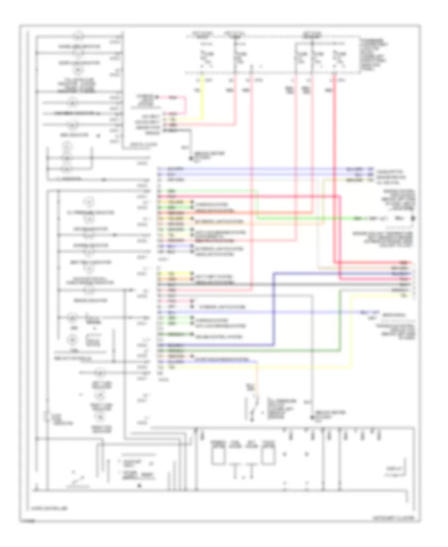
INSTRUMENT CLUSTER
Instrument Cluster Wiring Diagram, with Trip Computer (1 of 2) for Hyundai Elantra GT 2003
 https://portal-diagnostov.com/license.html
Automotive Electricians Portal FZCO
Automotive Electricians Portal FZCO
https://portal-diagnostov.com/license.html
https://portal-diagnostov.com/license.html
Automotive Electricians Portal FZCO
Automotive Electricians Portal FZCO
List of elements for Instrument Cluster Wiring Diagram, with Trip Computer (1 of 2) for Hyundai Elantra GT 2003:
- (4 door)
- (5 door)
- (behind center of dash) g11
- (behind center of dash) g13
- Abs
- Abs active module
- Acc/on input
- Anti-lock brakes system
- Anti-theft system
- Brake indicator
- C86-1
- Charge indicator
- Consumption
- Cruise control system
- Cruise indicator
- Digital clock
- Dim input
- Display
- Door ajar indicator
- Ect gauge
- Engine control module (ecm) (behind left side of dash, above kick panel)
- Engine coolant temperature (ect) sensor & sender (on rear of engine, near coolant outlet)
- Engine rpm sig
- Exterior lights system
- Front fog indicator
- Fuel gauge
- Fuse 10a
- Fuse 15a
- Gear signal
- Ground
- Headlights system
- High beam indicator
- Hot at all times
- Hot in acc or on
- Hot in on or start
- I/p-f
- I/p-g
- I/p-h
- Illumination
- Immobilizer indicator
- Indicator
- Instrument cluster
- Interior lights system
- Left turn indicator
- Low fuel indicator
- M10-1
- M10-2
- Malfunction (mil) check engine indicator
- Memory pwr
- Micro controller
- Mil ind ctrl
- Oil pressure indicator
- Oil pressure switch (lower left rear of engine)
- On/start input
- Passenger compartment junction block (under left side of dash, near kick panel)
- Pnk
- Red
- Reset
- Right turn indicator
- Seat belt indicator
- Solid state
- Speedo- meter
- Srs indicator
- Starting/charging system
- Tacho- meter
- Tail gate ajar
- Tcs
- Transaxle control module (tcm) (behind left side of dash)
- Trunk lid ajar
- Warning system
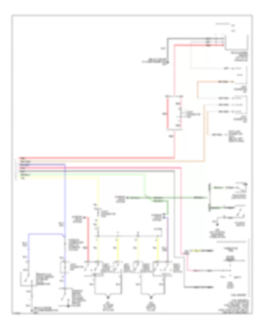
Instrument Cluster Wiring Diagram, with Trip Computer (2 of 2) for Hyundai Elantra GT 2003
 https://portal-diagnostov.com/license.html
Automotive Electricians Portal FZCO
Automotive Electricians Portal FZCO
https://portal-diagnostov.com/license.html
https://portal-diagnostov.com/license.html
Automotive Electricians Portal FZCO
Automotive Electricians Portal FZCOList of elements for Instrument Cluster Wiring Diagram, with Trip Computer (2 of 2) for Hyundai Elantra GT 2003:
- (below master cylinder reservoir) g23
- (not used)
- 4 door
- A/t
- Brake fluid level sensor (in brake fluid reservoir)
- Data link connector (dlc) (below left side of dash)
- Diode z01 (under dash, right of steering column)
- Empty
- Fuel level float
- Fuel sender
- Fuel sender & fuel pump motor (fuel sender : inside top of fuel tank) (fuel pump motor : below center of rear seat)
- Full
- G01 (at base of left "b" pillar)
- G03 (under right "b" pillar)
- G28 (on tailgate, near rear wiper motor)
- Gauge sender
- Interior lights system
- J/c m46
- Joint connector c91
- Joint connector c92
- Joint connector m33
- Joint connector m36
- Left front door switch
- Left rear door switch
- M/t
- Nca
- Parking brake switch (on base of parking brake lever)
- Pnk
- Red
- Right front door switch
- Right rear door switch
- Tailgate switch
- Thermistor
- Trunk room lamp switch
- Vehicle speed sensor (on top of transaxle)
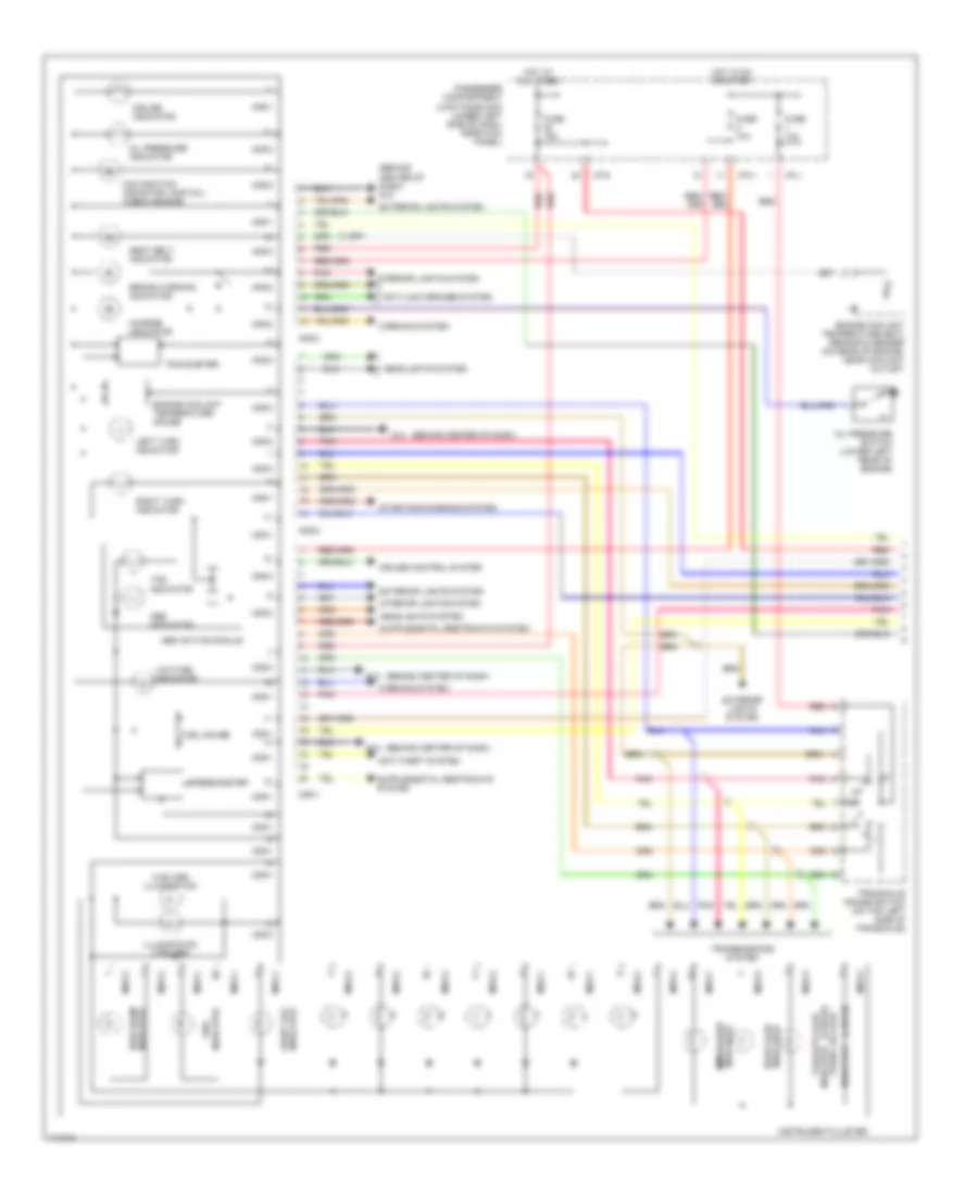
Instrument Cluster Wiring Diagram, without Trip Computer (1 of 2) for Hyundai Elantra GT 2003
 https://portal-diagnostov.com/license.html
Automotive Electricians Portal FZCO
Automotive Electricians Portal FZCO
https://portal-diagnostov.com/license.html
https://portal-diagnostov.com/license.html
Automotive Electricians Portal FZCO
Automotive Electricians Portal FZCOList of elements for Instrument Cluster Wiring Diagram, without Trip Computer (1 of 2) for Hyundai Elantra GT 2003:
- (2 bulbs) illumination
- (4 door)
- (5 door)
- (behind center of dash)
- (behind center of dash) g12
- Abs active module
- Abs indicator
- Anti-lock brakes system
- Anti-theft system
- Brake warning indicator
- Charge indicator
- Cruise control system
- Cruise indicator
- Door ajar indicator
- Engine coolant temperature (ect) sensor & sender (on rear of engine, near coolant outlet)
- Engine coolant temperature gauge
- Exterior lights system
- Front fog indicator
- Fuel gauge
- Fuse 10a
- Fuse 15a
- G12
- G13
- G14
- Headlights system
- High beam indicator
- Hot at all times
- Hot in on or start
- I/p-g
- I/p-h
- I/p-j
- Illumination (4 bulbs)
- Indicator
- Indicator immobilizer
- Instrument cluster
- Interior lights system
- Left turn indicator
- Low fuel indicator
- M09-1
- M09-2
- M09-3
- Malfunction indicator lamp (mil) "check engine"
- Mo9-1
- Mo9-2
- Mo9-3
- Oil pressure indicator
- Oil pressure switch (lower left rear of engine)
- Passenger compartment junction block (under left side of dash, near kick panel)
- Pnk
- Red
- Right turn indicator
- Seat belt indicator
- Speedometer
- Srs indicator
- Starting/charging system
- Tachometer
- Tailgate ajar
- Tcs indicator
- Transaxle range switch (on top left side of transaxle)
- Transmissions system
- Trunk lid ajar
- Warning system
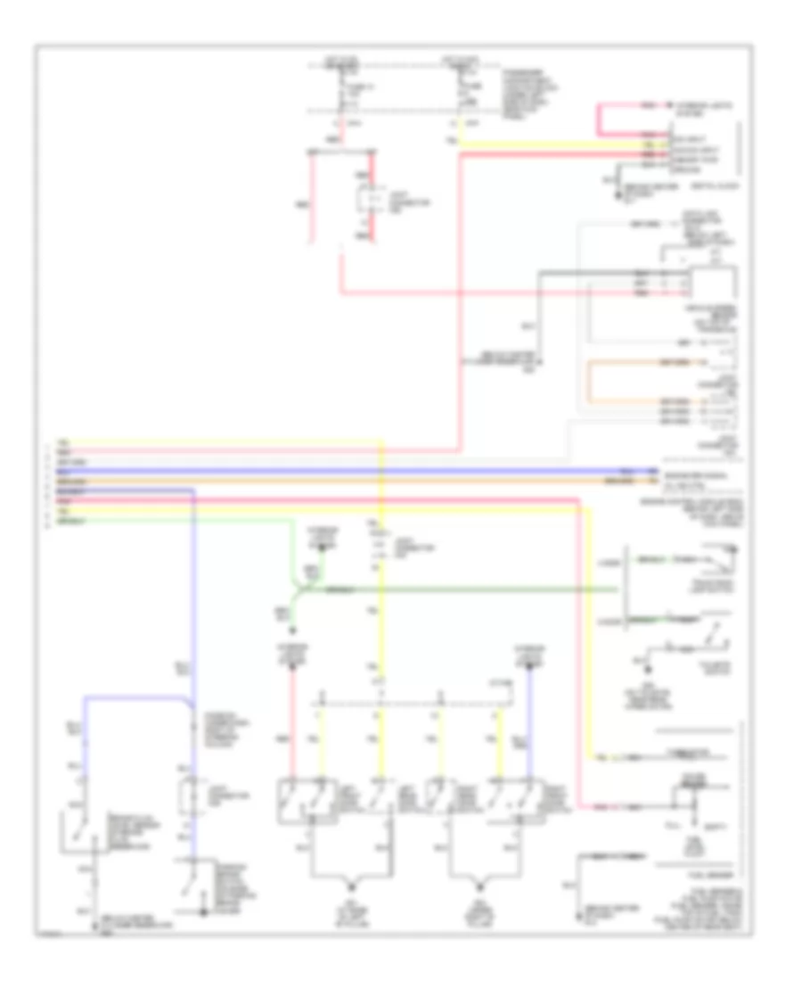
Instrument Cluster Wiring Diagram, without Trip Computer (2 of 2) for Hyundai Elantra GT 2003
 https://portal-diagnostov.com/license.html
Automotive Electricians Portal FZCO
Automotive Electricians Portal FZCO
https://portal-diagnostov.com/license.html
https://portal-diagnostov.com/license.html
Automotive Electricians Portal FZCO
Automotive Electricians Portal FZCOList of elements for Instrument Cluster Wiring Diagram, without Trip Computer (2 of 2) for Hyundai Elantra GT 2003:
- (behind center of dash) g11
- (behind center of dash) g13
- (below left
- (below master
- (below master cylinder reservoir) g23
- (dlc)
- (on top of transaxle)
- 4 door
- 5 door
- A/t
- Acc/on input
- Brake fluid level sensor (in brake fluid reservoir)
- C91
- Connector
- Cylinder reservoir)
- Data link
- Digital clock
- Dim input
- Diode z01 (under dash, right of steering column)
- Empty
- Engine control module (ecm) (behind left side of dash, above kick panel)
- Engine rpm signal
- Fuel level float
- Fuel sender
- Fuel sender & fuel pump motor (fuel sender: inside top of fuel tank) (fuel pump motor: below center of rear seat)
- Full
- Fuse 10 10a
- Fuse 10a
- G01 (at base of left "b" pillar)
- G03 (under right "b" pillar)
- G23
- G28 (on tailgate, near rear wiper motor)
- Gauge sender
- Ground
- Hot in acc or on
- Hot in on or start
- I/p-f
- I/p-h
- Interior lights system
- J/c m46
- Joint
- Joint connector c92
- Joint connector m33
- Joint connector m36
- Left front door switch
- Left rear door switch
- M/t
- M33
- Memory pwr
- Mil ind ctrl
- Nca
- Parking brake switch (on base of parking brake lever)
- Passenger compartment junction block (under left side of dash, near kick panel)
- Pnk
- Red
- Right front door switch
- Right rear door switch
- Sensor
- Side of dash)
- Tailgate switch
- Thermistor
- Trunk room lamp switch
- Vehicle speed

 Čeština
 Dansk
Dansk Deutsch
 Ελληνικά
 English
 English
 Español
 Suomi
Suomi Français
 Français
 עברית
עברית Hrvatski
 Magyar
 Italiano
 한국어
한국어 Nederlands
 Polski
 Português
 Português
 Română
 Русский
 Slovenčina
 Slovenščina
 Svenska
 Türkçe
 中文 (中国)
