POWER DISTRIBUTION
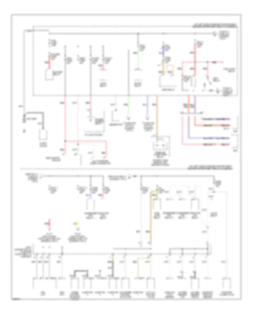
Power Distribution Wiring Diagram (1 of 4) for Hyundai Accent GLS 2006
 https://portal-diagnostov.com/license.html
Automotive Electricians Portal FZCO
Automotive Electricians Portal FZCO
https://portal-diagnostov.com/license.html
https://portal-diagnostov.com/license.html
Automotive Electricians Portal FZCO
Automotive Electricians Portal FZCO
List of elements for Power Distribution Wiring Diagram (1 of 4) for Hyundai Accent GLS 2006:
- (diagram 1 of 4)
- (on left side of engine compartment) engine compartment relay & fuse box
- A/con 1 fuse 10a
- A/con relay
- A/t
- Abs 1 fuse 40a
- Abs 2 fuse 40a
- Abs control module
- Batt 1 fuse 50a
- Batt 2 fuse 30a
- Battery
- Blower fuse 40a
- Blower relay
- Burglar alarm horn relay
- C01-1
- C01-2
- C13-1
- C13-2
- C13-3
- C13-4
- Camshaft position sensor
- Canister close valve
- Cond fuse 30a
- Condenser fan relay 1
- Condenser fan relay 2
- Cvvt oil control valve
- Ecm
- Ecm (m/t)
- Ecu a fuse 30a
- Ecu b fuse 10a
- Ecu c fuse 20a
- From ecu a fuse 30a a
- From main relay b
- Fuel pump relay
- Generator
- Horn fuse 10a
- Horn relay
- I/p junction box
- Icm relay box (behind left center of dash)
- Idle speed control actuator
- Ign 1 fuse 30a
- Ign 2 fuse 40a
- Inj fuse 15a
- Injector
- Joint connector c12 (in engine compt relay & fuse box)
- M/t
- Main fuse 125a
- Main relay
- Mass air flow sensor
- Motor
- Multipurpose check connector
- Nca
- Oxygen sensor (down)
- Oxygen sensor (up)
- P/wdw fuse 30a
- Pcm
- Pcm (a/t)
- Power window relay
- Purge control solenoid valve
- Rad fuse 30a
- Radiator fan relay
- Red
- Snsr fuse 10a
- Start
- Start relay
- To batt 1 fuse, 50a (diagram 1 of 4)
- To ecu c fuse, 20a (diagram 1 of 4)
- To i/p junction box, hazard fuse, 10a (diagram 4 of 4)
- To i/p junction box, htd glass fuse, 30a (diagram 3 of 4)
- To ignition switch (diagram 2 of 4)
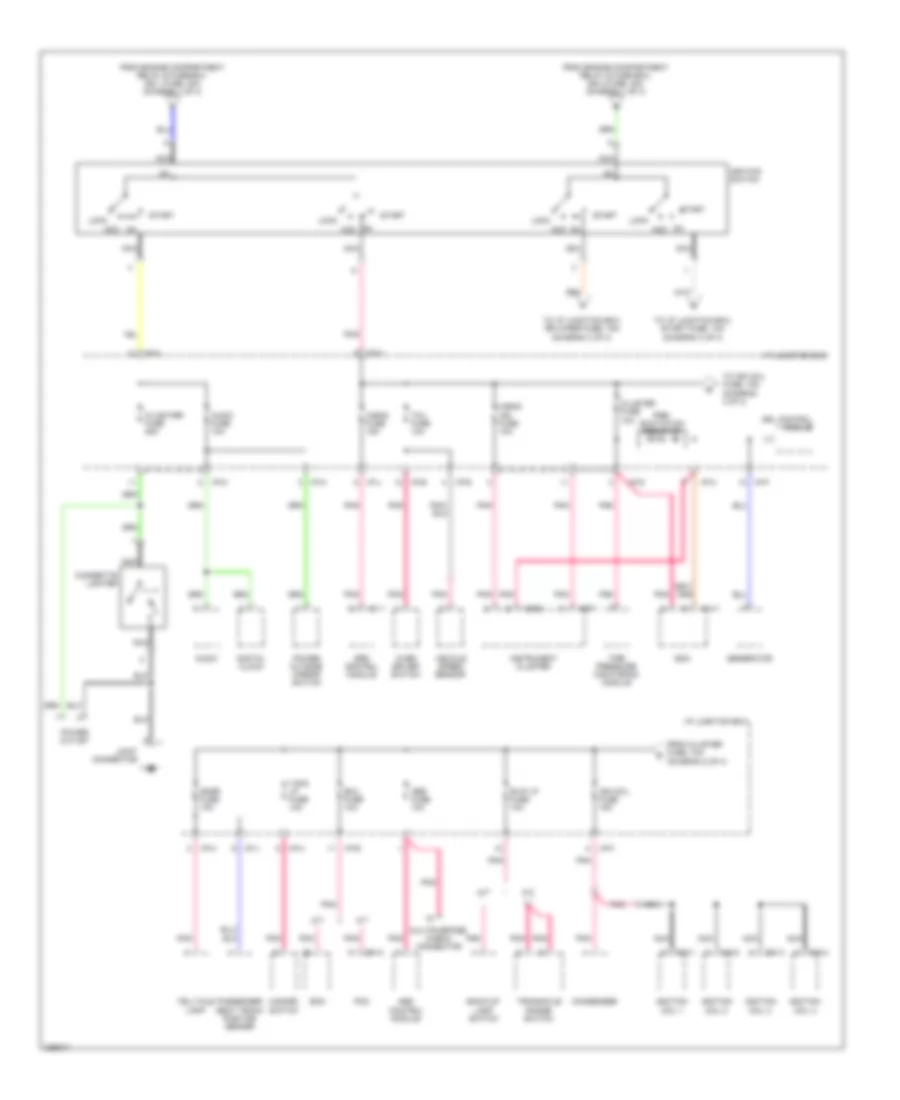
Power Distribution Wiring Diagram (2 of 4) for Hyundai Accent GLS 2006
 https://portal-diagnostov.com/license.html
Automotive Electricians Portal FZCO
Automotive Electricians Portal FZCO
https://portal-diagnostov.com/license.html
https://portal-diagnostov.com/license.html
Automotive Electricians Portal FZCO
Automotive Electricians Portal FZCOList of elements for Power Distribution Wiring Diagram (2 of 4) for Hyundai Accent GLS 2006:
- A/bag fuse 15a
- A/bag ind fuse 10a
- A/t
- Abs control module
- Abs fuse 10a
- Acc
- Audio
- Audio fuse 10a
- B/up lp fuse 10a
- Back-up lamp switch
- Bcm
- C/lighter fuse 25a
- C01-2
- C10-1
- C10-2
- C10-3
- C10-4
- Cigarette lighter
- Cluster fuse 10a
- Condenser
- Digital clock
- Drl control module
- Ecm
- Ecu fuse 10a
- From cluster fuse, 10a (diagram 2 of 4)
- From engine compartment relay & fuse box, ign 1 fuse, 30a (diagram 1 of 4)
- From engine compartment relay & fuse box, ign 2 fuse, 40a (diagram 1 of 4)
- Generator
- Hazard switch
- I/p junction box
- I/p-a
- I/p-b
- I/p-e
- I/p-f
- I/p-g
- I/p-h
- I/p-j
- I/p-m
- I01-1
- Ign coil fuse 15a
- Ignition coil 1
- Ignition coil 2
- Ignition coil 3
- Ignition coil 4
- Ignition switch
- Instrument cluster
- Joint connector
- Lock
- Lock acc
- M/t
- M09-1
- M09-2
- M14-1
- Multipurpose check connector
- Nca
- Over driver switch
- Passenger seat track position sensor
- Pcm
- Pnk
- Power outlet
- Power outside mirror switch
- Pre- excitation resistor
- Snsr fuse 10a
- Srs control module
- Start
- T/sig lp fuse 10a
- Tcu fuse 10a
- Telltale lamp
- Tire pressure monitoring module
- To i/p junction box, rr wiper fuse, 15a (diagram 3 of 4)
- To i/p junction box, start fuse, 10a (diagram 4 of 4)
- To ign coil fuse, 15a (diagram 2 of 4)
- Transaxle range switch
- Vehicle speed sensor
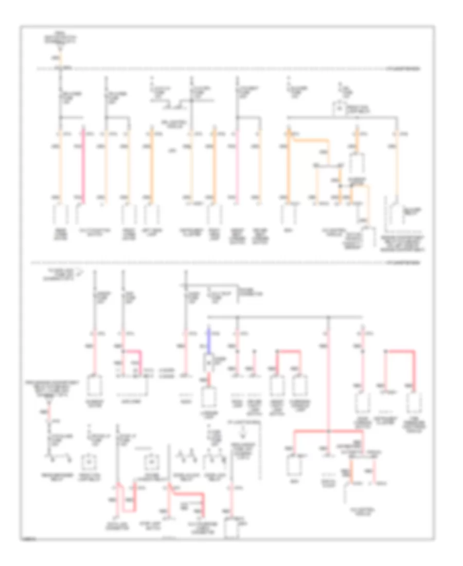
Power Distribution Wiring Diagram (3 of 4) for Hyundai Accent GLS 2006
 https://portal-diagnostov.com/license.html
Automotive Electricians Portal FZCO
Automotive Electricians Portal FZCO
https://portal-diagnostov.com/license.html
https://portal-diagnostov.com/license.html
Automotive Electricians Portal FZCO
Automotive Electricians Portal FZCOList of elements for Power Distribution Wiring Diagram (3 of 4) for Hyundai Accent GLS 2006:
- (3 door)
- (4 door)
- (diagram 3 of 4)
- A/c control module
- A/t
- Active incar & humidity sensor
- Amp fuse 25a
- Amplifier
- Assist seat warmer switch
- Assist vanity lamp switch
- Audio
- Audio fuse 15a
- Automatic a/c
- Bcm
- Blower fuse 10a
- Blower relay
- C/dr lock fuse 20a
- Data link connector
- Digital clock
- Diode z01
- Door lock relay
- Door unlock relay
- Door warning switch
- Driver seat warmer switch
- Driver vanity lamp switch
- Drl control module
- Engine compartment relay & fuse box (on left side of engine compartment)
- F01-2
- F41-2
- Fr fog lp fuse 10a
- Fr wiper fuse 25a
- From engine compartment relay & fuse box, batt 1 fuse, 50a (diagram 1 of 4)
- From ignition switch (diagram 2 of 4)
- From s/roof fuse, 20a (diagram 3 of 4)
- Front fog lamp relay
- Front wiper motor
- H/lp (lh) fuse 10a
- H/lp (rh) fuse 10a
- Htd glass fuse 30a
- Htd seat fuse 20a
- I/p junction box
- I/p-a
- I/p-b
- I/p-c
- I/p-d
- I/p-e
- I/p-f
- I/p-g
- I/p-k
- I/p-m
- I/p-n
- Ign fuse 10a
- Instrument cluster
- Left head lamp
- Luggage lamp
- M/t
- M04-2
- M09-1
- M14-1
- M14-2
- M16-1
- Manual a/c
- Mult b/up fuse 10a
- Multi-function switch
- Multipurpose check connector
- Overhead console lamp
- Pnk
- Power connector
- Power window relay
- Rear defogger relay
- Rear wiper motor
- Red
- Right head lamp
- Room lamp
- Rr wiper fuse 15a
- S/roof fuse 20a
- Stop lamp switch
- Stop lp fuse 15a
- Sunroof motor
- Tire pressure monitoring module
- To cd/r lock fuse, 20a k
- Usa
- W/o abs
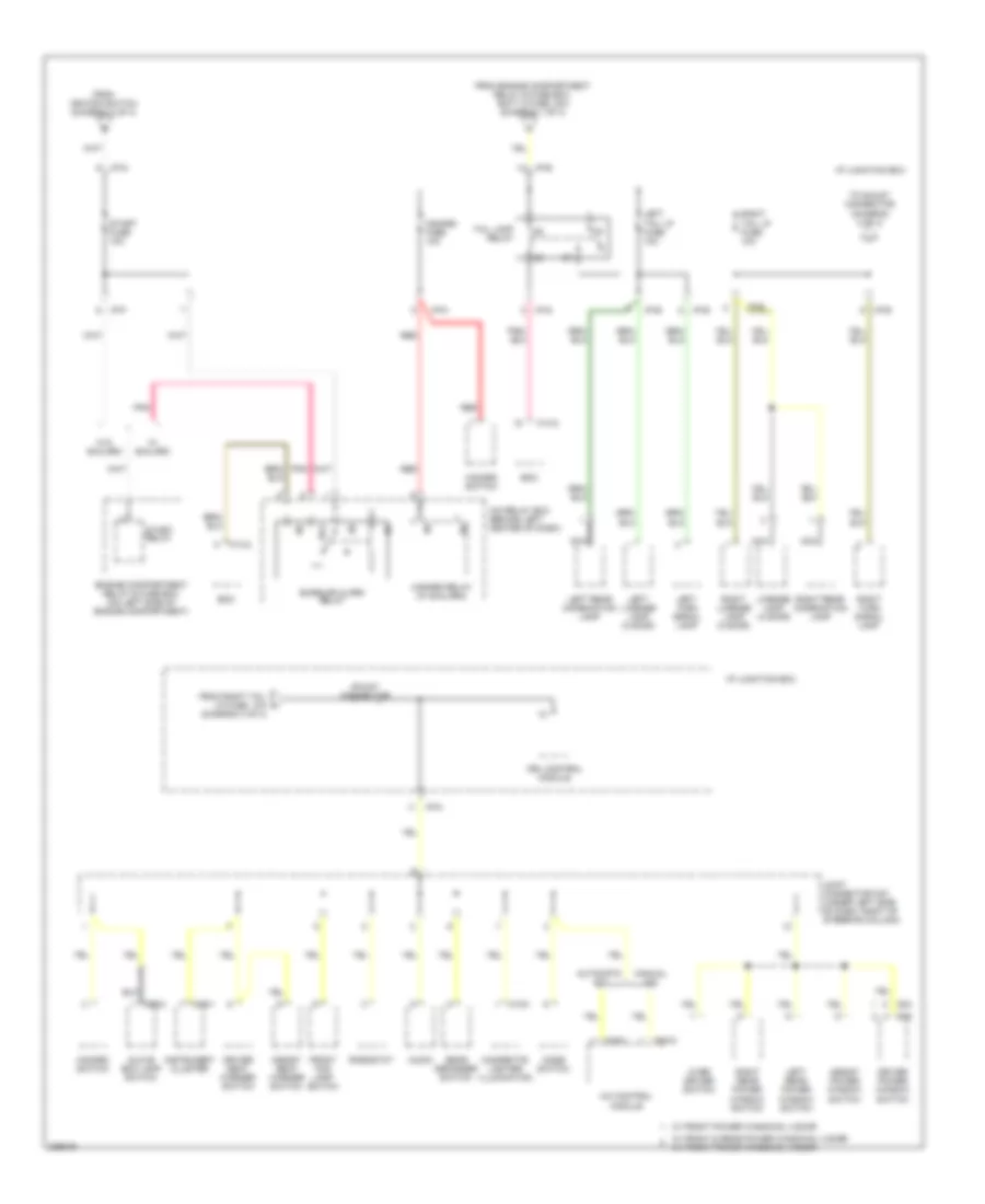
Power Distribution Wiring Diagram (4 of 4) for Hyundai Accent GLS 2006
 https://portal-diagnostov.com/license.html
Automotive Electricians Portal FZCO
Automotive Electricians Portal FZCO
https://portal-diagnostov.com/license.html
https://portal-diagnostov.com/license.html
Automotive Electricians Portal FZCO
Automotive Electricians Portal FZCOList of elements for Power Distribution Wiring Diagram (4 of 4) for Hyundai Accent GLS 2006:
- (diagram 4 of 4)
- 87a
- A/c control module
- Assist power window switch
- Assist seat warmer switch
- Audio
- Automatic a/c
- Bcm
- Burglar alarm relay
- Cigarette lighter illumination
- D04
- D05
- Driver power window switch
- Driver seat warmer switch
- Drl control module
- Engine compartment relay & fuse box (on left side of engine compartment)
- From engine compartment relay & fuse box, batt 2 fuse, 30a (diagram 1 of 4)
- From ignition switch (diagram 2 of 4)
- From right tail lp fuse, 10a l
- Front fog lamp switch
- Glove box lamp switch
- Hazard fuse 10a
- Hazard relay (w/ b/alarm)
- Hazard switch
- I/p junction box
- I/p-b
- I/p-e
- I/p-f
- I/p-g
- I/p-n
- Icm relay box (behind left center of dash)
- Instrument cluster
- Joint connector m27 (under left side of dash, right of steering column)
- Left license lamp (3 door)
- Left rear combination lamp
- Left rear power window switch
- Left tail lp fuse 10a
- Left turn signal lamp
- License lamp (4 door)
- M04-2
- M09-1
- M10a
- M14-2
- M16-1
- M66-2
- Manual a/c
- Mode switch
- Nca
- Over driver switch
- Pnk
- Rear defogger switch
- Red
- Rheostat
- Right license lamp (3 door)
- Right rear combination lamp
- Right rear power window switch
- Right tail lp fuse 10a
- Right turn signal lamp
- Shunt connector
- Start fuse 10a
- Start relay
- Tail lamp relay
- To shunt connector (diagram 4 of 4)
- W/ b/alarm
- W/ front & rear power windows, 4 door w/ front power windows, 3 door
- W/ front power windows, 4 door
- W/o b/alarm

 Čeština
 Dansk
Dansk Deutsch
 Ελληνικά
 English
 English
 Español
 Suomi
Suomi Français
 Français
 עברית
עברית Hrvatski
 Magyar
 Italiano
 한국어
한국어 Nederlands
 Polski
 Português
 Português
 Română
 Русский
 Slovenčina
 Slovenščina
 Svenska
 Türkçe
 中文 (中国)
