ANTI-LOCK BRAKES
Anti-lock Brake Wiring Diagrams for Dodge Pickup R1500 1999
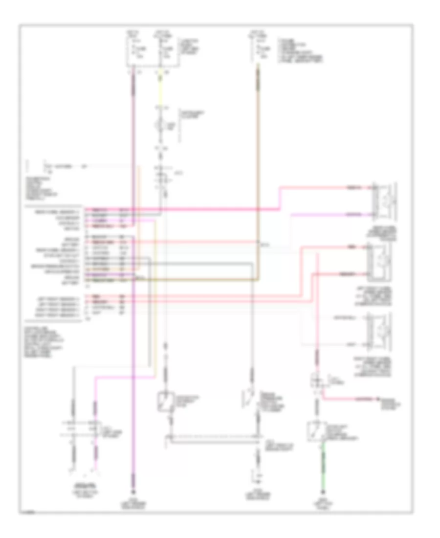
List of elements for Anti-lock Brake Wiring Diagrams for Dodge Pickup R1500 1999:
- (left bottom of dash)
- 4wd ind
- 4wd sensor
- 4wd switch (on front axle)
- A10
- A20
- B113
- B114
- Battery
- Brake pressure switch
- Brake pressure switch (on master cylinder)
- Ccd bus (+)
- Ccd bus (-)
- Controller anti-lock brake (4wabs: eng compt, on top of hydraulic control unit) (rwal: in eng compt, on left inner fender panel)
- Data link connector
- Engine controls system
- Fuse 10a
- Fuse 40a
- G100 (left fender side shield)
- G107
- G200 (left kick panel)
- Ground
- Hot at all times
- Hot in run
- Ignition
- Instrument cluster
- J/c 1 (in pdc)
- J/c 3
- J/c 4 (left front of engine compt)
- J/c 7 (left side of dash)
- Junction block (left end of dash)
- Left front sensor (+)
- Left front sensor (-)
- Left front wheel speed sensor (w/ all wheel abs) (on left front steering knuckle)
- Power distribution center (in engine compt, on left inner fender panel, near battery)
- Powertrain control module (in eng compt, on right side of firewall)
- Rear wheel sensor (+)
- Rear wheel sensor (-)
- Rear wheel speed sensor (in differential housing)
- Red
- Right front sensor (+)
- Right front sensor (-)
- Right front wheel speed sensor (w/ all wheel abs) (on right front steering knuckle)
- S112
- S113
- Stoplight sw out
- Stoplight switch (on brake pedal bracket)
- V40
- Vehicle speed sig
 Čeština
 Dansk
Dansk Deutsch
 Ελληνικά
 English
 English
 Español
 Suomi
Suomi Français
 Français
 עברית
עברית Hrvatski
 Magyar
 Italiano
 한국어
한국어 Nederlands
 Polski
 Português
 Português
 Română
 Русский
 Slovenčina
 Slovenščina
 Svenska
 Türkçe
 中文 (中国)
 日本語
日本語