SUPPLEMENTAL RESTRAINTS
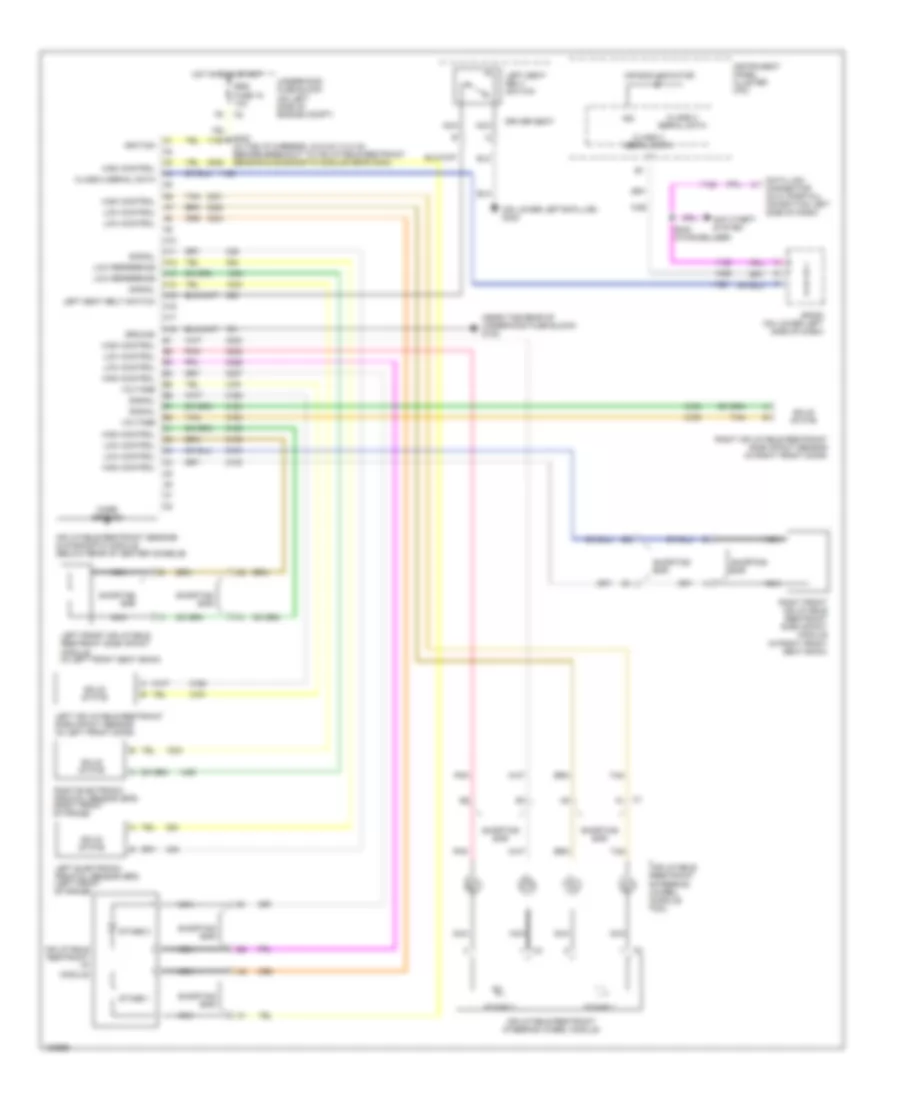
Supplemental Restraints Wiring Diagram for Buick Rainier 2004
List of elements for Supplemental Restraints Wiring Diagram for Buick Rainier 2004:
- (near the rear of underhood fuse block) g102
- (on lower left b-pillar) g302
- A10
- A11
- A12
- A13
- A14
- A15
- A16
- A17
- A18
- Air bag indicator
- Anti-theft system
- Bar
- C1 a1
- Case ground
- Class 2 serial data
- Data link connector (dlc) (partial) (on bottom left side of dash)
- Driver seat
- Ground
- High control
- Hot in on & start
- Ign
- Ignition
- Inflatable restraint i/p module
- Inflatable restraint sensing & diagnostic module (below rear of center console)
- Inflatable restraint steering wheel module
- Inflatable restraint steering wheel module coil
- Instrument panel cluster (ipc)
- Left electronic frontal sensor (efs) (left front of frame)
- Left front inflatable restraint side impact module (in left front seat back)
- Left inflatable restraint side impact sensor (in left front door)
- Left seat belt switch
- Low control
- Low reference
- Nca
- Pnk
- Right electronic frontal sensor (efs) (right front of frame)
- Right front inflatable restraint side impact module (in right front seat back)
- Right inflatable restraint side impact sensor (in right front door)
- S232 (in the i/p harness, 33.5 cm (13.2 in) before breakout to inflatable restraint sensing & diagnostic module near c304)
- S232 (w/immobilizer)
- Shorting
- Shorting bar
- Signal
- Solid state
- Sp205 (on lower left side of dash)
- Srs fuse 18 10a
- Stage 1
- Stage 2
- Tan
- Underhood fuse block (on left side of engine compt)
- Voltage
 Čeština
 Dansk
Dansk Deutsch
 Ελληνικά
 English
 English
 Español
 Suomi
Suomi Français
 Français
 עברית
עברית Hrvatski
 Magyar
 Italiano
 한국어
한국어 Nederlands
 Polski
 Português
 Português
 Română
 Русский
 Slovenčina
 Slovenščina
 Svenska
 Türkçe
 中文 (中国)
 日本語
日本語