AIR CONDITIONING
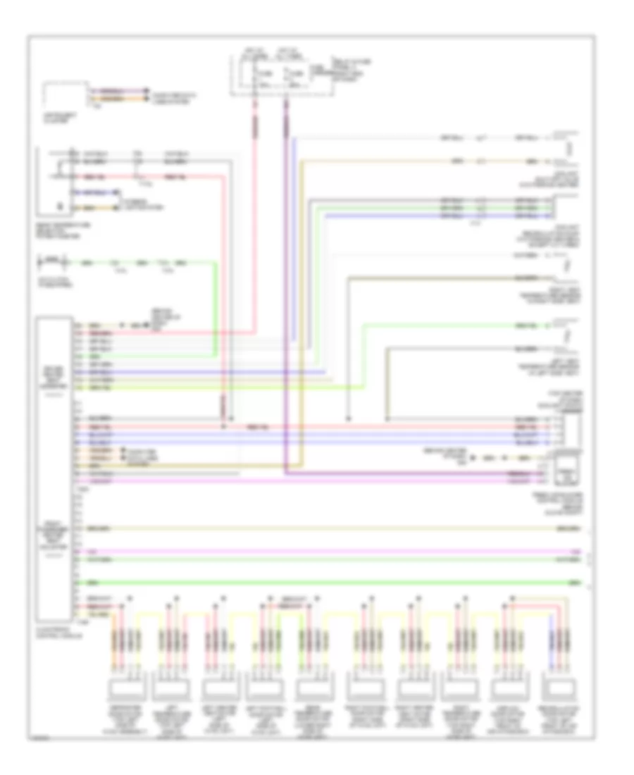
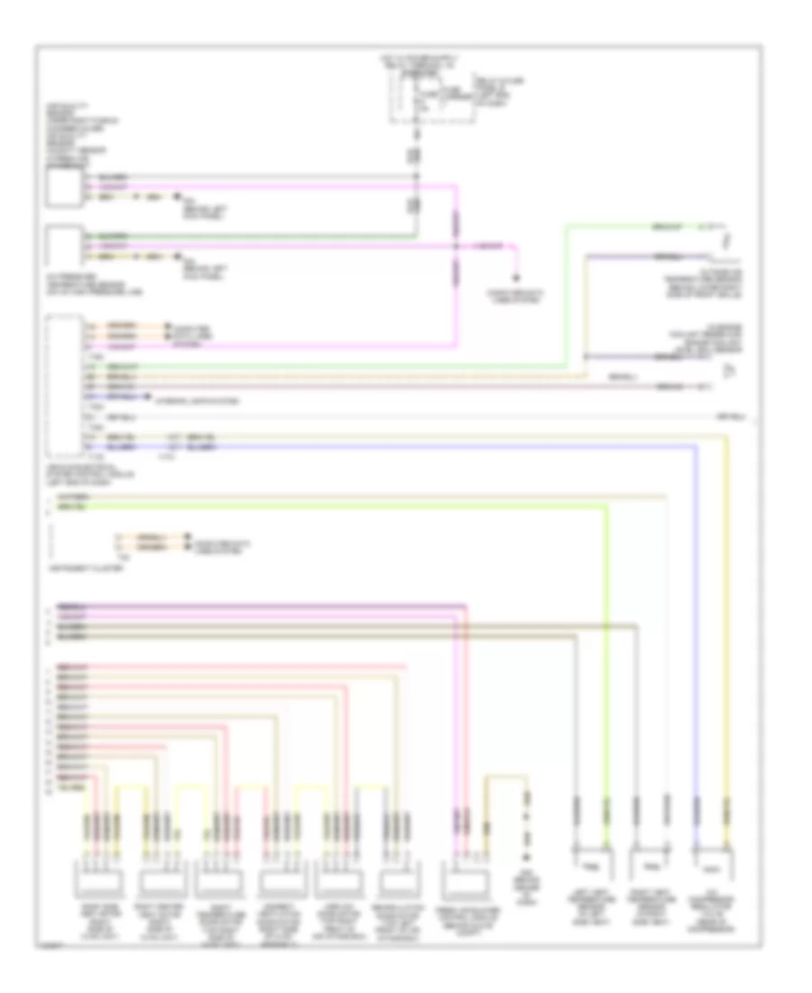
Automatic A/C Wiring Diagram, Basic (1 of 3) for Audi A6 Quattro TDI Premium Plus 2014
 https://portal-diagnostov.com/license.html
Automotive Electricians Portal FZCO
Automotive Electricians Portal FZCO
https://portal-diagnostov.com/license.html
https://portal-diagnostov.com/license.html
Automotive Electricians Portal FZCO
Automotive Electricians Portal FZCO
List of elements for Automatic A/C Wiring Diagram, Basic (1 of 3) for Audi A6 Quattro TDI Premium Plus 2014:
- (behind center of dash) g45
- (top center of dash) sunlight photo sensor
- A/c clutch (if equipped)
- Airflow door motor (top right front of air intake box)
- Climatronic control module
- Computer data lines system
- Coolant recirculation pump (w/o parking heater & except 2.0 turbo)
- Coolant shut-off valve (w/o parking heater)
- Defroster door motor (top left side of hvac assembly)
- Driver heated seat adjuster
- Fresh air blower
- Fresh air blower control module (behind glove compt)
- Front passenger heated seat adjuster
- Fuse 10a
- Fuse 40a
- Fuse carrier
- Hot at all times
- Instrument cluster
- Interior lights system
- Left center vent motor (left side of hvac unit)
- Left footwell door motor (left side of hvac unit)
- Left temperature door motor (top left side of hvac unit)
- Left vent temperature sensor (in left side vent)
- Rear temperature door motor (lower right side of hvac unit)
- Rear temperature selection potentiometer
- Recirculation door motor (top left front of air intake box)
- Relay & fuse panel c (right end of dash)
- Right center vent motor (right side of hvac unit)
- Right footwell door motor (right side of hvac unit)
- Right temperature door motor (top right side of hvac unit)
- Right vent temperature sensor (in right side vent)
- T16p
- T17i
- T17q
- T20c
- T32
- Ti7a
- Ti7h
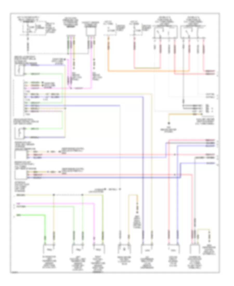
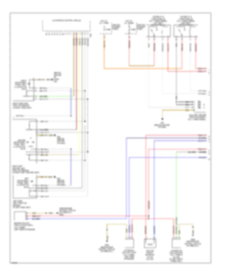
Automatic A/C Wiring Diagram, Basic (2 of 3) for Audi A6 Quattro TDI Premium Plus 2014
 https://portal-diagnostov.com/license.html
Automotive Electricians Portal FZCO
Automotive Electricians Portal FZCO
https://portal-diagnostov.com/license.html
https://portal-diagnostov.com/license.html
Automotive Electricians Portal FZCO
Automotive Electricians Portal FZCOList of elements for Automatic A/C Wiring Diagram, Basic (2 of 3) for Audi A6 Quattro TDI Premium Plus 2014:
- (behind lower right side of front grille) outside air temperature sensor
- (near engine control module on firewall) g645
- (on a/c high pressure line) a/c pressure/ temperature sensor
- (on relay & fuse panel b) (3.0l turbo diesel) high heat output relay
- (on relay & fuse panel b) (3.0l turbo diesel) low heat output relay
- (or red)
- A/c compressor regulator valve (rear of compressor)
- After-run coolant pump (4.0l turbo) (left side of engine)
- Auxiliary heater heating element (3.0l turbo diesel)
- Charge air cooling pump (3.0l sc & 4.0l turbo) (in left front wheelwell)
- Computer data lines system
- Cooling circuit solenoid valve (3.0l sc)
- Engine coolant circulation pump 2 (4.0l turbo) (left rear of engine)
- Engine coolant level (ecl) sensor (in engine coolant reservoir)
- Evaporator vent temperature sensor (right side of hvac unit)
- Fuse
- Fuse 5a
- Fuse carrier
- G44 (behind left kick panel)
- G45 (behind center of dash)
- G645 (near engine control module on on firewall)
- G687 (right front side of center tunnel)
- Heating element fuse 1
- Heating element fuse 2
- Hot at all times
- Humidity sensor in fresh air intake duct
- Interior lights system
- Left footwell vent temperature sensor (lower left side of hvac unit)
- Panel)
- Rear center air vent illumination bulb
- Relay & fuse panel b (left end of dash)
- Right footwell vent temperature sensor (right side of hvac assembly)
- T16c
- T17a
- T17d
- T32a
- Vehicle electrical system control module (left end of dash)
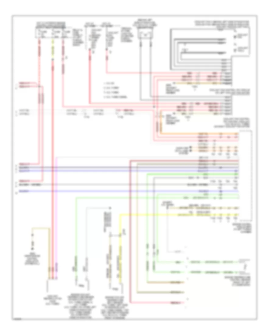
Automatic A/C Wiring Diagram, Basic (3 of 3) for Audi A6 Quattro TDI Premium Plus 2014
 https://portal-diagnostov.com/license.html
Automotive Electricians Portal FZCO
Automotive Electricians Portal FZCO
https://portal-diagnostov.com/license.html
https://portal-diagnostov.com/license.html
Automotive Electricians Portal FZCO
Automotive Electricians Portal FZCOList of elements for Automatic A/C Wiring Diagram, Basic (3 of 3) for Audi A6 Quattro TDI Premium Plus 2014:
- (behind left side of radiator) (3.0l sc & 4.0l turbo) coolant fan 2
- (coolant fan 2: behind left side of radiator) (coolant fan: behind right side of radiator) coolant fan/coolant fan 2
- (or red)
- 11a
- 16a
- 2.0l turbo
- 3.0l sc
- 3.0l turbo diesel
- 4.0l turbo
- Computer data lines system
- Coolant fan
- Coolant fan 2
- Coolant fan control (fc) control module 2 (3.0l sc & 4.0l turbo) (on right coolant fan motor)
- Coolant fan control (fc) module (on left coolant fan motor)
- Coolant fan fuse 40a/ 60a/ 80a
- Coolant fan second speed fuse 40a/ 60a/ 80a
- Coolant recirculation pump (2.0l turbo)
- Engine control module (ecm) (in left plenum chamber)
- Engine coolant temperature (ect) sensor (2.0l turbo: left side of engine block) (3.0l turbo diesel: top left center of engine) (3.0l sc & 4.0l turbo: front of engine)
- Engine coolant temperature sensor on radiator outlet (3.0l turbo diesel & 4.0l turbo) (4.0l turbo: on lower left hose on radiator) (3.0l turbo diesel: on lower right hose on radiator)
- Engine temperature control sensor (front of left cylinder bank)
- Except 2.0l turbo
- Fuse 15a
- Fuse 5a
- G645 (near engine control module on on firewall)
- G685 (on right front long member)
- Hot at all times
- Nca
- Red
- Relay & fuse panel a (in left plenum chamber e-box)
- T105
- T14a
- T14b
- T17b
- T17g
- T4fm
- T4fn
- T60
- T91
- T94
- Terminal 30 wire junction (in center plenum chamber)
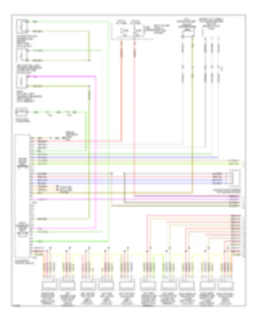
Automatic A/C Wiring Diagram, Comfort (1 of 4) for Audi A6 Quattro TDI Premium Plus 2014
 https://portal-diagnostov.com/license.html
Automotive Electricians Portal FZCO
Automotive Electricians Portal FZCO
https://portal-diagnostov.com/license.html
https://portal-diagnostov.com/license.html
Automotive Electricians Portal FZCO
Automotive Electricians Portal FZCOList of elements for Automatic A/C Wiring Diagram, Comfort (1 of 4) for Audi A6 Quattro TDI Premium Plus 2014:
- (behind center of dash) g45
- (except 2.0l turbo & w/o parking heater) coolant recirculation pump
- (w/o parking heater)
- A/c clutch (if equipped)
- Climatronic control module
- Computer data lines system
- Coolant shut-off valve
- Defroster door motor (top left side of hvac assembly)
- Driver heated seat adjuster
- Evaporator vent temperature sensor (right side of hvac unit)
- Front passenger heated seat adjuster
- Fuse 10a
- Fuse 40a
- Fuse carrier
- Hot at all times
- Left center vent motor (left side of hvac unit)
- Left footwell door motor (left side of hvac unit)
- Left footwell vent temperature sensor (lower left side of hvac unit)
- Left rear air door motor (lower left side of hvac assembly)
- Left rear temperature door motor (lower left side of hvac assembly)
- Left side vent motor (left side of hvac unit)
- Left temperature door motor (top left side of hvac unit)
- Relay & fuse panel c (right end of dash)
- Right footwell door motor (right side of hvac unit)
- Right footwell vent temperature sensor (right side of hvac assembly)
- Right rear air door motor (lower right side of hvac unit)
- Right rear temperature door motor (lower right side of hvac unit)
- Sunlight photo sensor (top center of dash)
- T16p
- T17i
- T20c
- Ti7a
- Ti7h
Automatic A/C Wiring Diagram, Comfort (2 of 4) for Audi A6 Quattro TDI Premium Plus 2014
 https://portal-diagnostov.com/license.html
Automotive Electricians Portal FZCO
Automotive Electricians Portal FZCO
https://portal-diagnostov.com/license.html
https://portal-diagnostov.com/license.html
Automotive Electricians Portal FZCO
Automotive Electricians Portal FZCOList of elements for Automatic A/C Wiring Diagram, Comfort (2 of 4) for Audi A6 Quattro TDI Premium Plus 2014:
- (air quality sensor: under right plenum chamber cover) air quality sensor/ humidity sensor in fresh air intake duct
- (in engine coolant reservoir) engine coolant level (ecl) sensor
- A/c compressor regulator valve (rear of compressor)
- A/c pressure/ temperature sensor (on a/c high pressure line)
- Airflow door motor (top right front of air intake box)
- Computer data lines system
- Fresh air blower control module (behind glove compt)
- Fuse 5a
- Fuse carrier
- G44 (behind left kick panel)
- G45 (behind center of dash)
- Indirect ventilation door motor (right side of hvac assembly)
- Instrument cluster
- Interior lights system
- Left vent temperature sensor (in left side vent)
- Outside air temperature sensor (behind lower right side of front grille)
- Recirculation door motor (top left front of air intake box)
- Relay & fuse panel b (left end of dash)
- Right center vent motor (right side of hvac unit)
- Right side vent motor (right side of hvac unit)
- Right temperature door motor (top right side of hvac unit)
- Right vent temperature sensor (in right side vent)
- T16c
- T17a
- T17d
- T32
- T32a
- T32c
- Vehicle electrical system control module (left end of dash)
Automatic A/C Wiring Diagram, Comfort (3 of 4) for Audi A6 Quattro TDI Premium Plus 2014
 https://portal-diagnostov.com/license.html
Automotive Electricians Portal FZCO
Automotive Electricians Portal FZCO
https://portal-diagnostov.com/license.html
https://portal-diagnostov.com/license.html
Automotive Electricians Portal FZCO
Automotive Electricians Portal FZCOList of elements for Automatic A/C Wiring Diagram, Comfort (3 of 4) for Audi A6 Quattro TDI Premium Plus 2014:
- (behind center of dash) g45
- (near engine control module on firewall) g645
- (on relay & fuse panel b) (3.0l turbo diesel) high heat output relay
- (on relay & fuse panel b) (3.0l turbo diesel) low heat output relay
- (or red)
- After-run coolant pump (4.0l turbo) (left side of engine)
- Auxiliary heater heating element (3.0l turbo diesel)
- Center instrument panel vent illumination bulb
- Charge air cooling pump (4.0l turbo & 3.0l sc) (in left front wheelwell)
- Climatronic control module
- Cooling circuit solenoid valve (3.0l sc)
- Engine coolant circulation pump 2 (4.0l turbo) (left rear of engine)
- Fuse
- G45 (behind center of dash)
- G645 (near engine control module on firewall)
- Heating element fuse 1
- Heating element fuse 2
- Hot at all times
- Left instrument panel vent illumination bulb
- Left side vent position sensor (in left side vent)
- Right instrument panel vent illumination bulb
- Right side vent position sensor (in right side vent)
- Right/left center vent position sensor (in right/left center vent)
- T16f
Automatic A/C Wiring Diagram, Comfort (4 of 4) for Audi A6 Quattro TDI Premium Plus 2014
 https://portal-diagnostov.com/license.html
Automotive Electricians Portal FZCO
Automotive Electricians Portal FZCO
https://portal-diagnostov.com/license.html
https://portal-diagnostov.com/license.html
Automotive Electricians Portal FZCO
Automotive Electricians Portal FZCOList of elements for Automatic A/C Wiring Diagram, Comfort (4 of 4) for Audi A6 Quattro TDI Premium Plus 2014:
- (behind left side of radiator) (3.0l sc & 4.0l turbo) coolant fan 2
- (coolant fan 2: behind left side of radiator) (coolant fan: behind right side of radiator) coolant fan/coolant fan 2
- (or red)
- 11a
- 16a
- 2.0l turbo
- 3.0l sc
- 3.0l turbo diesel
- 4.0l turbo
- Computer data lines system
- Coolant fan
- Coolant fan 2
- Coolant fan control (fc) control module 2 (3.0l sc & 4.0l turbo) (on right coolant fan motor)
- Coolant fan control (fc) module (on left coolant fan motor)
- Coolant fan fuse 40a/ 60a/ 80a
- Coolant fan second speed fuse 40a/ 60a/ 80a
- Coolant recirculation pump (2.0l turbo)
- Engine control module (ecm) (in left plenum chamber)
- Engine coolant temperature (ect) sensor (2.0l turbo: left side of engine block) (3.0l turbo diesel: top left center of engine) (3.0l sc & 4.0l turbo: front of engine)
- Engine coolant temperature sensor on radiator outlet (3.0l turbo diesel & 4.0l turbo) (4.0l turbo: on lower left hose on radiator) (3.0l turbo diesel: on lower right hose on radiator)
- Engine temperature control sensor (front of left cylinder bank)
- Except 2.0l turbo
- Fuse 15a
- Fuse 5a
- G645 (near engine control module on on firewall)
- G685 (on right front long member)
- Hot at all times
- Nca
- Red
- Relay & fuse panel a (in left plenum chamber e-box)
- T105
- T14a
- T14b
- T17b
- T17g
- T4fm
- T4fn
- T60
- T91
- T94
- Terminal 30 wire junction (in center plenum chamber)
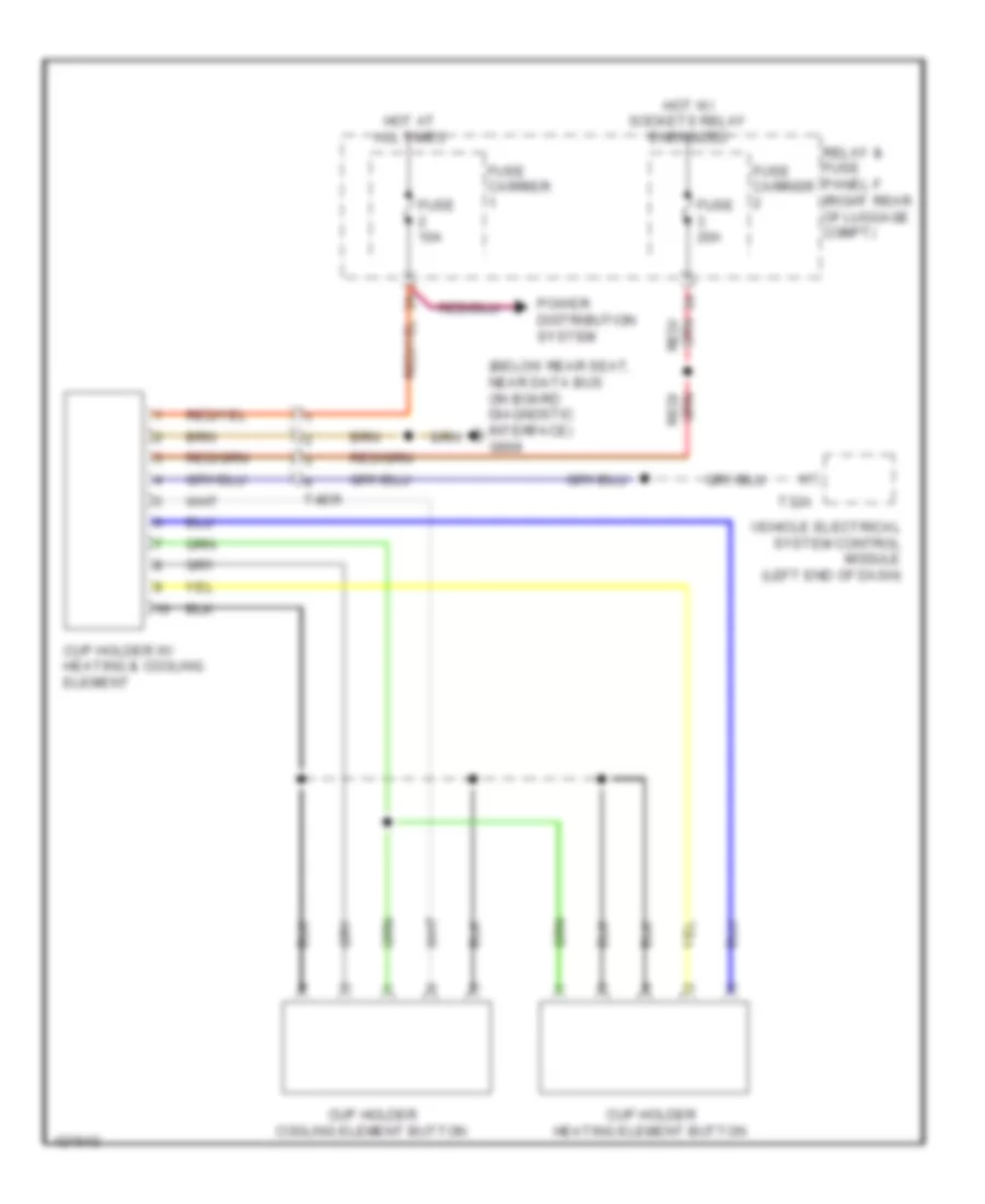
Heated And Cooled Cup Holder Wiring Diagram for Audi A6 Quattro TDI Premium Plus 2014
 https://portal-diagnostov.com/license.html
Automotive Electricians Portal FZCO
Automotive Electricians Portal FZCO
https://portal-diagnostov.com/license.html
https://portal-diagnostov.com/license.html
Automotive Electricians Portal FZCO
Automotive Electricians Portal FZCOList of elements for Heated And Cooled Cup Holder Wiring Diagram for Audi A6 Quattro TDI Premium Plus 2014:
- (below rear seat, near data bus on board diagnostic interface) g688
- Cup holder cooling element button
- Cup holder heating element button
- Cup holder w/ heating & cooling element
- Fuse 10a
- Fuse 20a
- Fuse carrier
- Hot at all times
- Hot w/ sockets relay energized
- Power distribution system
- Relay & fuse panel f (right rear of luggage compt)
- T32a
- T4er
- Vehicle electrical system control module (left end of dash)
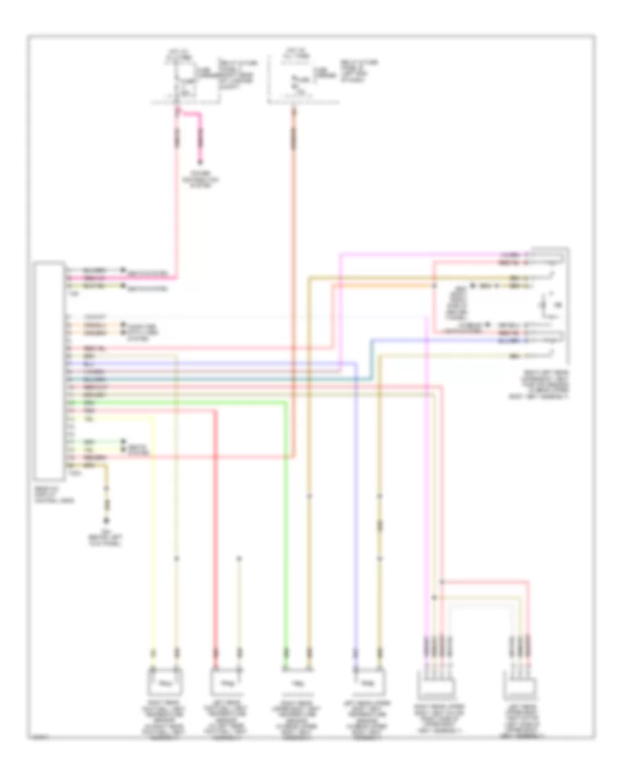
Rear A/C Wiring Diagram for Audi A6 Quattro TDI Premium Plus 2014
 https://portal-diagnostov.com/license.html
Automotive Electricians Portal FZCO
Automotive Electricians Portal FZCO
https://portal-diagnostov.com/license.html
https://portal-diagnostov.com/license.html
Automotive Electricians Portal FZCO
Automotive Electricians Portal FZCOList of elements for Rear A/C Wiring Diagram for Audi A6 Quattro TDI Premium Plus 2014:
- 11a
- Computer data lines system
- Fuse 10a
- Fuse 30a
- Fuse carrier
- G44 (behind left kick panel)
- G687 (right front side of center tunnel)
- Hot at all times
- Interior lights system
- Left rear footwell vent temperature sensor (in left rear footwell vent assembly)
- Left rear upper body vent motor (left side of upper body vent assembly)
- Left rear upper body vent temperature sensor (in rear upper body vent assembly)
- Power distribution system
- Rear a/c display control head
- Red
- Relay & fuse panel b (left end of dash)
- Relay & fuse panel f (right rear of luggage compt)
- Right rear footwell vent temperature sensor (in right rear footwell vent assembly)
- Right rear upper body vent motor (right side of upper body vent assembly)
- Right rear upper body vent temperature sensor (in rear upper body vent assembly)
- Right/left rear upper body vent position sensor (in rear upper body vent assembly)
- Seats system
- T20a
- T3r

 Čeština
 Dansk
Dansk Deutsch
 Ελληνικά
 English
 English
 Español
 Suomi
Suomi Français
 Français
 עברית
עברית Hrvatski
 Magyar
 Italiano
 한국어
한국어 Nederlands
 Polski
 Português
 Português
 Română
 Русский
 Slovenčina
 Slovenščina
 Svenska
 Türkçe
 中文 (中国)
