BODY CONTROL MODULES
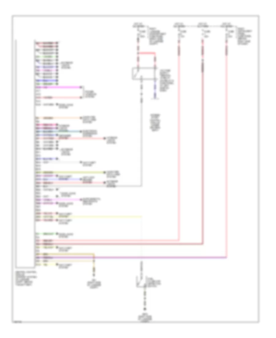
Body Control Modules Wiring Diagram for Audi A8 Quattro 2005
 https://portal-diagnostov.com/license.html
Automotive Electricians Portal FZCO
Automotive Electricians Portal FZCO
https://portal-diagnostov.com/license.html
https://portal-diagnostov.com/license.html
Automotive Electricians Portal FZCO
Automotive Electricians Portal FZCO
List of elements for Body Control Modules Wiring Diagram for Audi A8 Quattro 2005:
- A10
- A11
- A12
- A13
- A14
- A15
- A58
- Access/ start control module (under driver's seat)
- Anti-lock brakes system
- Anti-theft system
- B10
- B11
- B12
- B13
- B14
- B15
- B16
- B17
- B18
- B19
- B20
- B21
- B22
- B23
- B24
- B25
- B26
- B27
- B28
- B29
- B30
- B31
- C10
- Central control module (comfort system) (in luggage compt, behind the battery)
- Computer data lines system
- Defogger system
- Door locks system
- Electronic suspension system
- Exterior lights system
- Fuel filler cap detection switch
- Fuse 10a
- Fuse 150a
- Fuse 20a
- G51 (right side of luggage compt)
- G675 (right side of luggage compt)
- Hot at all times
- Interior lights system
- Power windows system
- Red
- Right instrument panel fuse panel (behind right side of dash)
- Right luggage compartment fuse panel (right side of luggage compt)
 Čeština
 Dansk
Dansk Deutsch
 Ελληνικά
 English
 English
 Español
 Suomi
Suomi Français
 Français
 עברית
עברית Hrvatski
 Magyar
 Italiano
 한국어
한국어 Nederlands
 Polski
 Português
 Português
 Română
 Русский
 Slovenčina
 Slovenščina
 Svenska
 Türkçe
 中文 (中国)
 日本語
日本語
