Čeština
 Dansk
Dansk Deutsch
 Ελληνικά
 English
 English
 Español
 Suomi
Suomi Français
 Français
 עברית
עברית Hrvatski
 Magyar
 Italiano
 한국어
한국어 Nederlands
 Polski
 Português
 Português
 Română
 Русский
 Slovenčina
 Slovenščina
 Svenska
 Türkçe
 中文 (中国)

СИСТЕМА КОНДИЦИОНЕРА
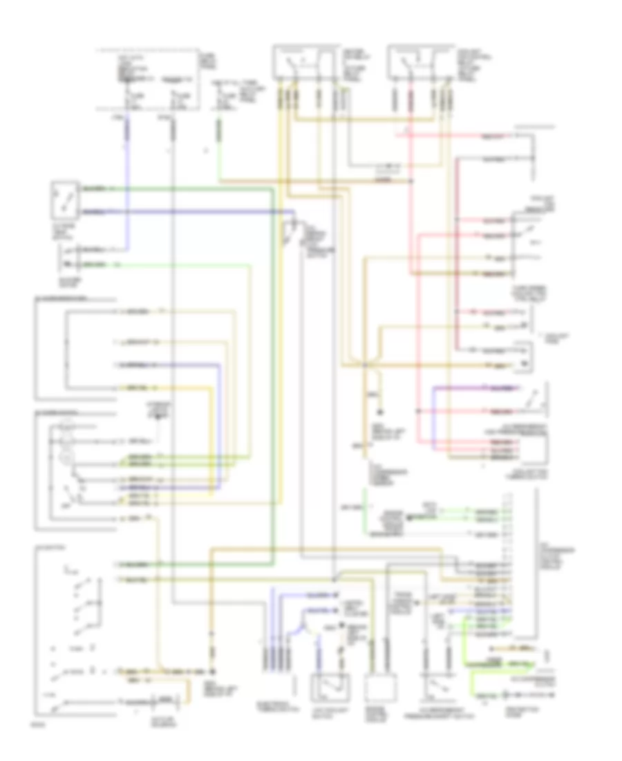
Автомобиль. Системная Монтажная схема A/C-Heater (С Электросхемой автоматической коробки передач АКПП 1 Из 2) для Audi 90 CS Quattro 1994


Автомобиль. Системная Монтажная схема A/C-Heater (С Электросхемой автоматической коробки передач АКПП 1 Из 2) для Audi 90 CS Quattro 1994 - Список элементов:
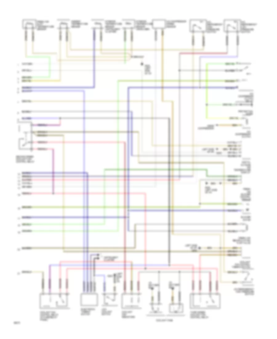
Автомобиль. Системная Монтажная схема A/C-Heater (С Электросхемой автоматической коробки передач АКПП 2 Из 2) для Audi 90 CS Quattro 1994
Автомобиль. Системная Монтажная схема A/C-Heater (С Электросхемой автоматической коробки передач АКПП 2 Из 2) для Audi 90 CS Quattro 1994 - Список элементов:
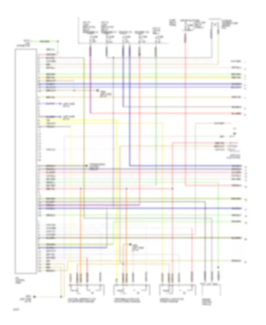
Автомобиль. Системная Монтажная схема A/C-Heater (Со Схемой M/T 1 Из 2) для Audi 90 CS Quattro 1994
Автомобиль. Системная Монтажная схема A/C-Heater (Со Схемой M/T 1 Из 2) для Audi 90 CS Quattro 1994 - Список элементов:
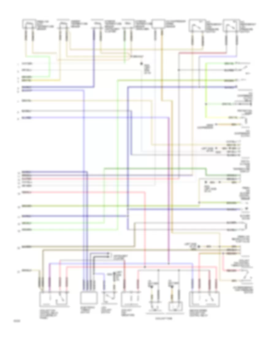
Автомобиль. Системная Монтажная схема A/C-Heater (Со Схемой M/T 2 Из 2) для Audi 90 CS Quattro 1994
Автомобиль. Системная Монтажная схема A/C-Heater (Со Схемой M/T 2 Из 2) для Audi 90 CS Quattro 1994 - Список элементов:
Электросхема кондиционера с ручный управлением для Audi 90 CS Quattro 1994
Электросхема кондиционера с ручный управлением для Audi 90 CS Quattro 1994 - Список элементов: