СИСТЕМА КОНДИЦИОНЕРА
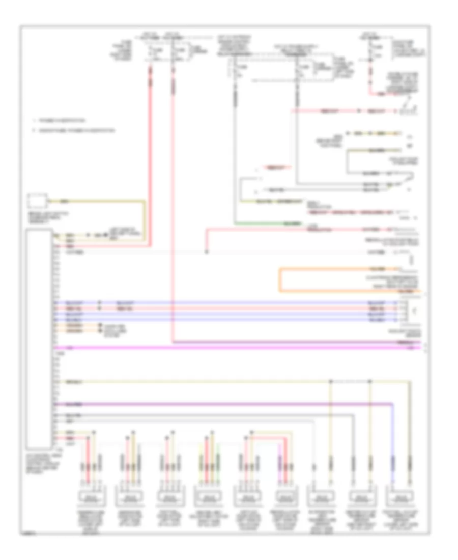
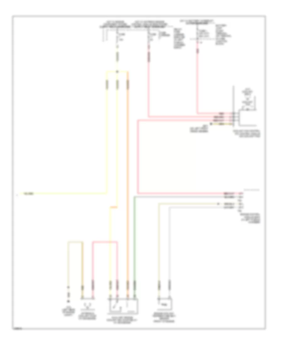
Электросхема кондиционера, Основная (1 из 2) для Audi A5 Quattro 2009
 https://portal-diagnostov.com/license.html
Automotive Electricians Portal FZCO
Automotive Electricians Portal FZCO
https://portal-diagnostov.com/license.html
https://portal-diagnostov.com/license.html
Automotive Electricians Portal FZCO
Automotive Electricians Portal FZCO
Электросхема кондиционера, Основная (1 из 2) для Audi A5 Quattro 2009 - Список элементов:
- (left side of center tunnel) g687
- (on relay/fuse carrier - sf, at right side of luggage compt) sockets relay
- 10a
- A/c control head climatronic control module (behind center of dash)
- Air flow door motor (left side of air intake housing)
- Brake light switch (on brake pedal assembly)
- Center outlet temperature sensor (center front of a/c unit)
- Center vent adjustment motor (right side of a/c unit)
- Climatronic refrigerant shut-off valve (right rear of engine)
- Computer data lines system
- Coolant pump (if equipped)
- Defroster door motor (left side of a/c unit)
- Discontinued, phased in modification
- Early production
- Evaporator vent temperature sensor (right side of a/c unit)
- Footwell door motor (left side of a/c unit)
- Footwell outlet temperature sensor (lower left side of a/c unit)
- Fuse 10a
- Fuse 110a
- Fuse 40a
- Fuse 5a
- Fuse carrier
- Fuse panel sc (under left side of dash)
- Fuse panel sd (under right side of dash)
- G638 (behind right kick panel)
- Hot at all times
- Late production
- Main fuse panel sa (on battery, in luggage compt)
- Phased in modification
- Recirculation door motor (left side of air intake housing)
- Recirculation pump relay (w/ coolant pump)
- Red
- Solid state
- Sunlight photo sensor
- T16i
- T20e
- Temperature regulator door motor (lower left side of a/c unit)
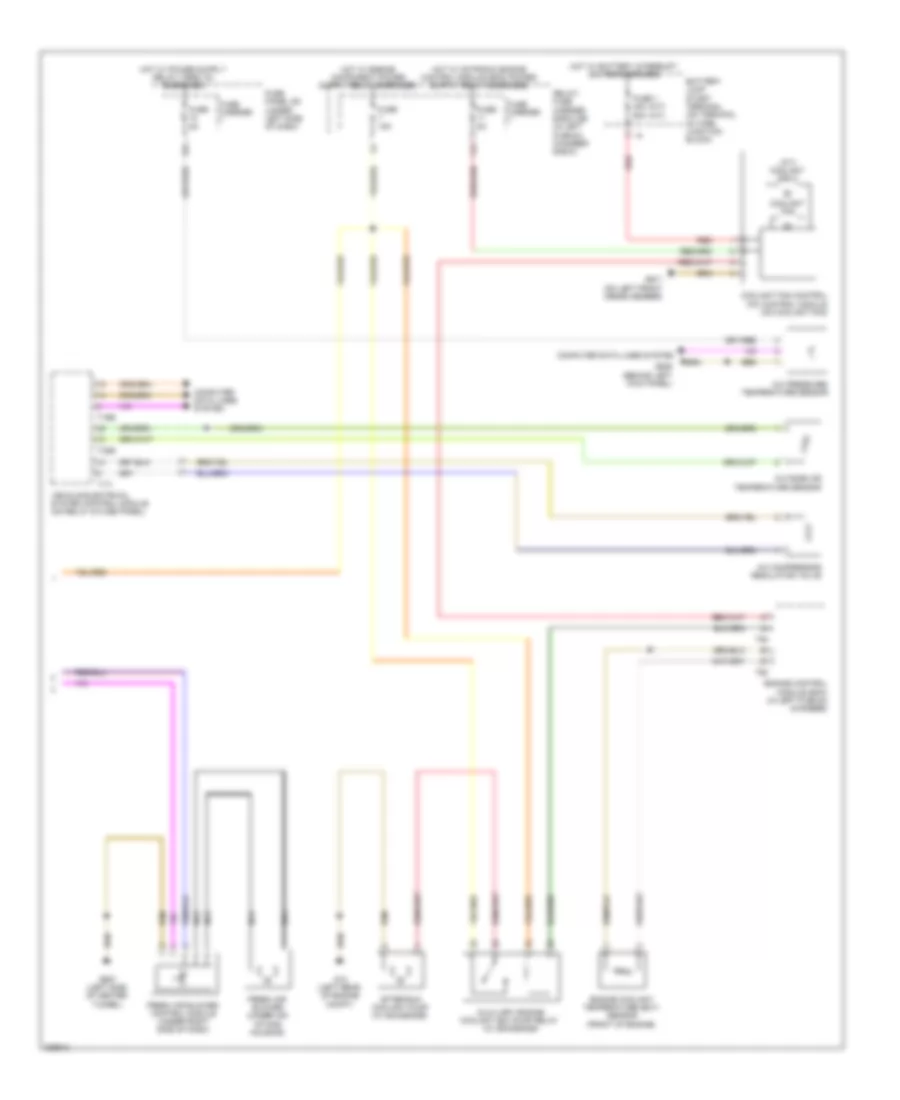
Электросхема кондиционера, Основная (2 из 2) для Audi A5 Quattro 2009
 https://portal-diagnostov.com/license.html
Automotive Electricians Portal FZCO
Automotive Electricians Portal FZCO
https://portal-diagnostov.com/license.html
https://portal-diagnostov.com/license.html
Automotive Electricians Portal FZCO
Automotive Electricians Portal FZCOЭлектросхема кондиционера, Основная (2 из 2) для Audi A5 Quattro 2009 - Список элементов:
- (a/t) coolant fan 2
- (m/t) (a/t)
- 11a
- 12a
- A/c compressor regulator valve
- A/c pressure/ temperature sensor
- After-run coolant pump (w/ 8z4/8z6/8z9)
- Auxiliary engine coolant (ec) pump relay (w/ 8z4/8z6/8z9)
- Battery jump start terminal (on terminal 30 wire junction block)
- Computer data lines system
- Coolant fan
- Coolant fan control (fc) control module (on coolant fan)
- Engine control module (ecm) (in left plenum chamber)
- Engine coolant temperature (ect) sensor (front of engine)
- Fresh air blower (under air intake housing)
- Fresh air blower control module (under right side of dash)
- Fuse 1 40a 60a
- Fuse 15a
- Fuse 5a
- Fuse carrier
- Fuse panel sc (under left side of dash)
- G12 (left rear of engine compt)
- G639 (behind left kick panel)
- G671 (on left front cross member)
- G687 (left side of center tunnel)
- Hot w/ battery interrupt igniter energized
- Nca
- Outside air temperature sensor
- Red
- Relay/ fuse carrier e-box sb (in left plenum chamber e-box)
- T16b
- T17i
- T32b
- T60
- T94
- Vehicle electrical system control module (on relay & fuse panel)
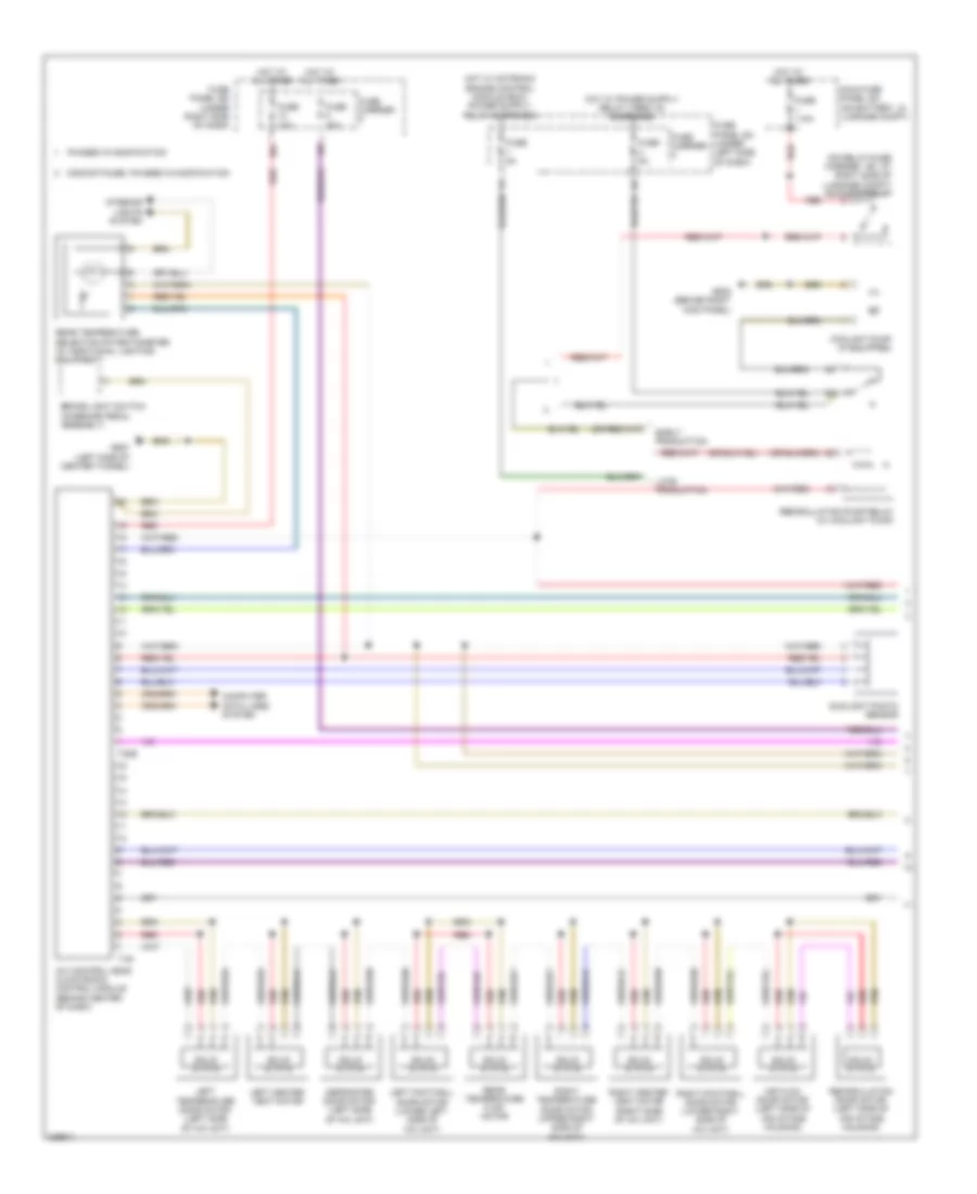
Электросхема кондиционера, Комфорт (1 из 3) для Audi A5 Quattro 2009
 https://portal-diagnostov.com/license.html
Automotive Electricians Portal FZCO
Automotive Electricians Portal FZCO
https://portal-diagnostov.com/license.html
https://portal-diagnostov.com/license.html
Automotive Electricians Portal FZCO
Automotive Electricians Portal FZCOЭлектросхема кондиционера, Комфорт (1 из 3) для Audi A5 Quattro 2009 - Список элементов:
- (on relay/fuse carrier - sf, at right side of luggage compt) sockets relay
- 10a
- A/c control head climatronic control module (behind center of dash)
- Air flow door motor (left side of air intake housing)
- Brake light switch (on brake pedal assembly)
- Computer data lines system
- Coolant pump (if equipped)
- Defroster door motor (left side of a/c unit)
- Discontinued, phased in modification
- Early production
- Fuse 10a
- Fuse 110a
- Fuse 40a
- Fuse 5a
- Fuse carrier
- Fuse panel sc (under left side of dash)
- Fuse panel sd (under right side of dash)
- G638 (behind right kick panel)
- G687 (left side of center tunnel)
- Hot at all times
- Interior lights system
- Late production
- Left center vent motor
- Left footwell door motor (lower left side of a/c unit)
- Left temperature door motor (left side of a/c unit)
- Main fuse panel sa (on battery, in luggage compt)
- Phased in modification
- Rear temperature flap motor
- Rear temperature selection potentiometer (w/ additional lighting equipment)
- Recirculation door motor (left side of air intake housing)
- Recirculation pump relay (w/ coolant pump)
- Red
- Right center vent motor (right side of a/c unit)
- Right footwell door motor (lower right side of a/c unit)
- Right temperature door motor (upper right side of a/c unit)
- Solid state
- Sunlight photo sensor
- T16i
- T20e
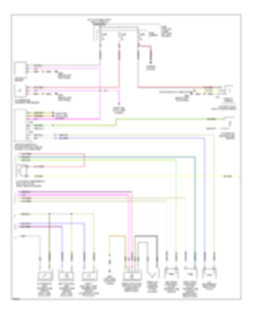
Электросхема кондиционера, Комфорт (2 из 3) для Audi A5 Quattro 2009
 https://portal-diagnostov.com/license.html
Automotive Electricians Portal FZCO
Automotive Electricians Portal FZCO
https://portal-diagnostov.com/license.html
https://portal-diagnostov.com/license.html
Automotive Electricians Portal FZCO
Automotive Electricians Portal FZCOЭлектросхема кондиционера, Комфорт (2 из 3) для Audi A5 Quattro 2009 - Список элементов:
- 12a
- A/c compressor regulator valve
- A/c pressure/ temperature sensor
- Air quality sensor
- Automatic day/ night interior mirror
- Climatronic refrigerant shut-off valve (right rear of engine)
- Computer data lines system
- Evaporator vent temperature sensor (right side of a/c unit)
- Fresh air blower (under air intake housing)
- Fresh air blower control module (under right side of dash)
- Fuse 5a
- Fuse carrier
- Fuse panel sc (under left side of dash)
- G639 (behind left kick panel)
- G687 (left side of center tunnel)
- Humidity sensor
- Left footwell vent temperature sensor (left side of a/c unit)
- Left front upper body outlet temperature sensor
- Mirrors system
- Nca
- Outside air temperature sensor
- Right footwell vent temperature sensor (lower right side of a/c unit)
- Right front upper body outlet temperature sensor (behind right side of dash)
- T16b
- T17i
- T32b
- T8c
- Vehicle electrical system control module (on relay & fuse panel)
Электросхема кондиционера, Комфорт (3 из 3) для Audi A5 Quattro 2009
 https://portal-diagnostov.com/license.html
Automotive Electricians Portal FZCO
Automotive Electricians Portal FZCO
https://portal-diagnostov.com/license.html
https://portal-diagnostov.com/license.html
Automotive Electricians Portal FZCO
Automotive Electricians Portal FZCOЭлектросхема кондиционера, Комфорт (3 из 3) для Audi A5 Quattro 2009 - Список элементов:
- (a/t) coolant fan 2
- (m/t) (a/t)
- 11a
- After-run coolant pump (w/ 8z4/8z6/8z9)
- Auxiliary engine coolant (ec) pump relay (w/ 8z4/8z6/8z9)
- Battery jump start terminal (on terminal 30 wire junction block)
- Coolant fan
- Coolant fan control (fc) control module (on coolant fan)
- Engine control module (ecm) (in left plenum chamber)
- Engine coolant temperature (ect) sensor (front of engine)
- Fuse 1 40a 60a
- Fuse 15a
- Fuse 5a
- Fuse carrier
- G12 (left rear of engine compt)
- G671 (on left front cross member)
- Hot w/ battery interrupt igniter energized
- Red
- Relay/ fuse carrier e-box sb (in left plenum chamber e-box)
- T60
- T94

 Čeština
 Dansk
Dansk Deutsch
 Ελληνικά
 English
 English
 Español
 Suomi
Suomi Français
 Français
 עברית
עברית Hrvatski
 Magyar
 Italiano
 한국어
한국어 Nederlands
 Polski
 Português
 Português
 Română
 Русский
 Slovenčina
 Slovenščina
 Svenska
 Türkçe
 中文 (中国)
