ENGINE PERFORMANCE
2.0L TURBO
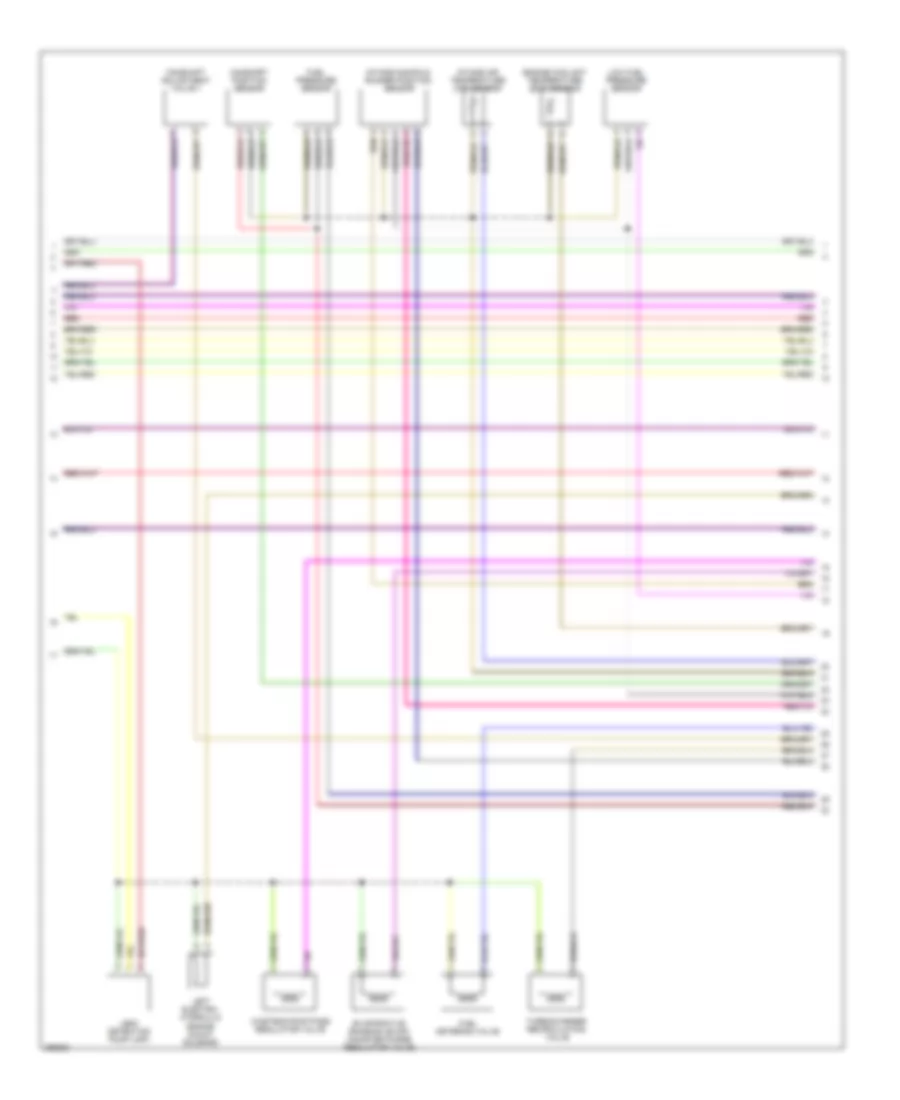
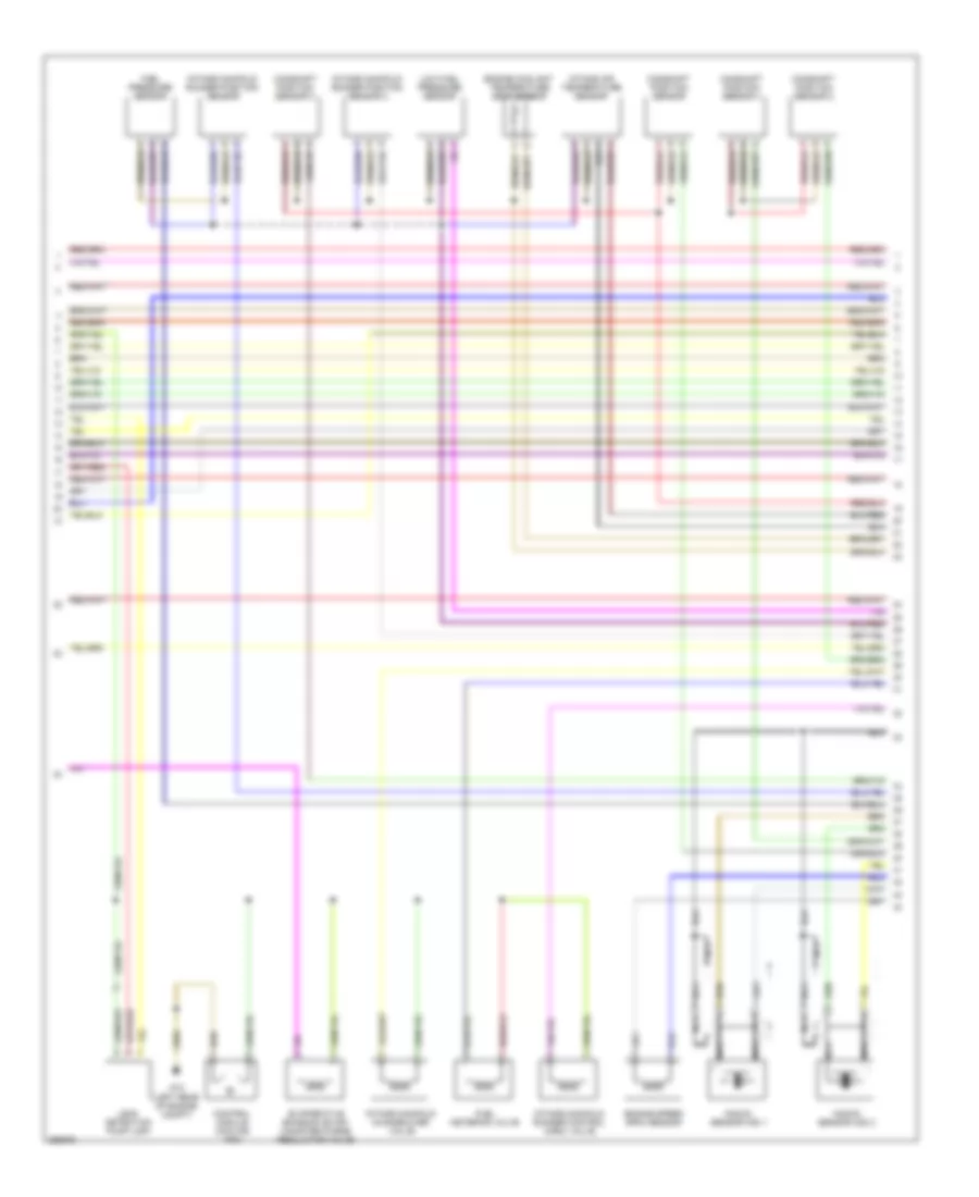
2.0L Turbo, Engine Performance Wiring Diagram (1 of 4) for Audi A4 Quattro 2007
 https://portal-diagnostov.com/license.html
Automotive Electricians Portal FZCO
Automotive Electricians Portal FZCO
https://portal-diagnostov.com/license.html
https://portal-diagnostov.com/license.html
Automotive Electricians Portal FZCO
Automotive Electricians Portal FZCO
List of elements for 2.0L Turbo, Engine Performance Wiring Diagram (1 of 4) for Audi A4 Quattro 2007:
- (left rear of engine compt) g12
- 14a
- Anti-theft system
- Brake- light switch
- Charge air pressure sensor
- Clutch pedal switch
- Cooling fans system
- Engine control module
- Fuse 10a
- Fuse 15a
- Fuse panel
- Fuse/ relay panel
- Heated oxygen sensor
- Hot at all times
- Hot in run or start
- Mass air flow (maf) sensor
- Oxygen sensor
- Partial
- Red
- Steering column electronic systems control module
- T16a
- T94
- Throttle position (tp) & accelerator pedal position (app) sensors
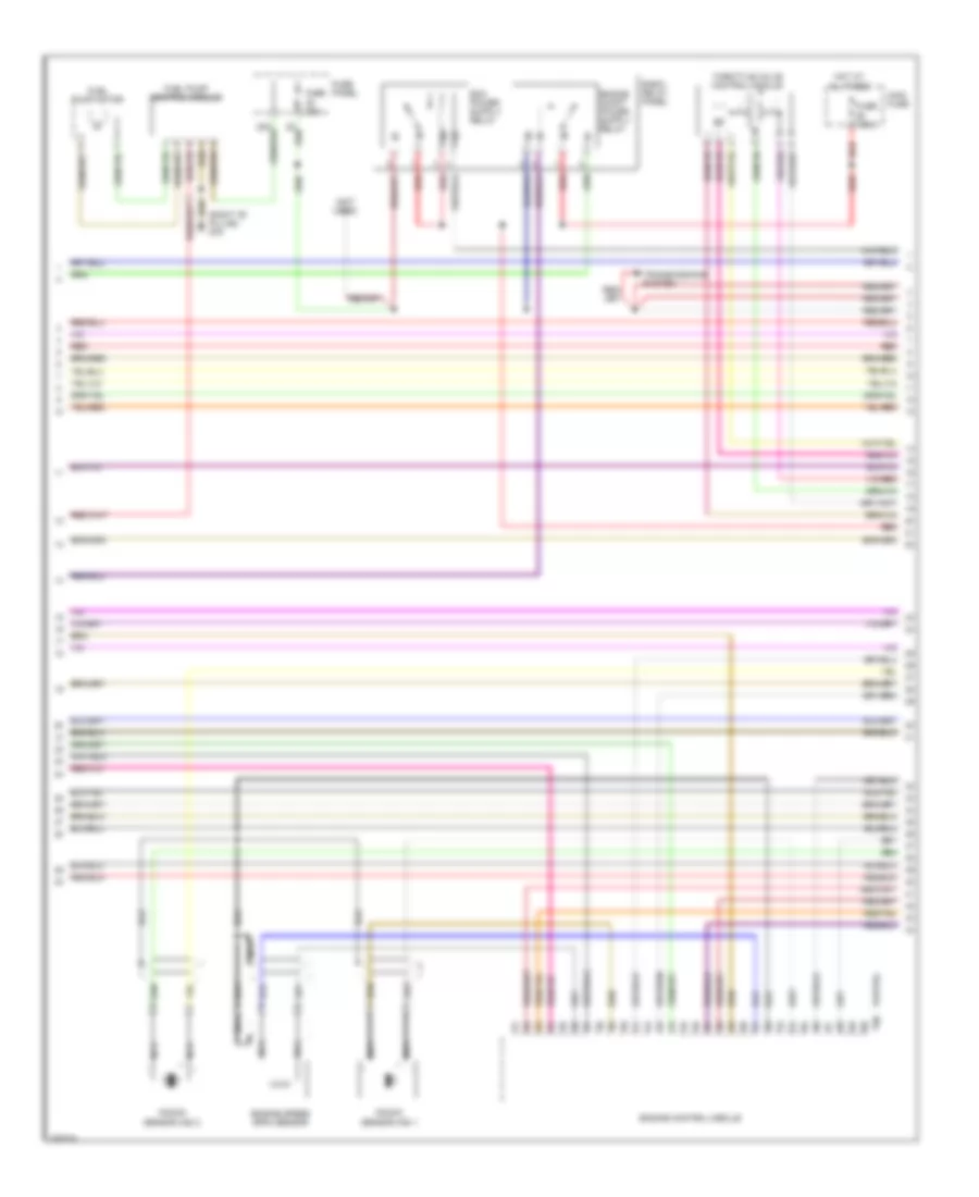
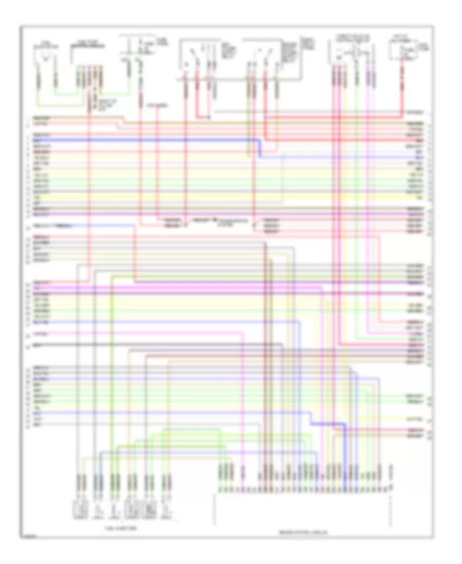
2.0L Turbo, Engine Performance Wiring Diagram (2 of 4) for Audi A4 Quattro 2007
 https://portal-diagnostov.com/license.html
Automotive Electricians Portal FZCO
Automotive Electricians Portal FZCO
https://portal-diagnostov.com/license.html
https://portal-diagnostov.com/license.html
Automotive Electricians Portal FZCO
Automotive Electricians Portal FZCOList of elements for 2.0L Turbo, Engine Performance Wiring Diagram (2 of 4) for Audi A4 Quattro 2007:
- Camshaft adjustment valve 1
- Camshaft position sensor
- Engine coolant temperature (ect) sensor
- Evaporative emission (evap) canister purge regulator valve
- Fuel metering valve
- Fuel pressure sensor
- Intake air temperature (iat) sensor
- Intake manifold runner position sensor
- Leak detection pump (ldp)
- Left electro- hydraulic engine mount solenoid
- Low fuel pressure sensor
- Red
- Turbocharger recirculating valve
- Wastegate bypass regulator valve
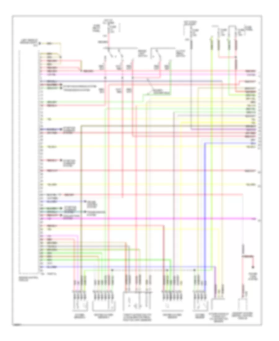
2.0L Turbo, Engine Performance Wiring Diagram (3 of 4) for Audi A4 Quattro 2007
 https://portal-diagnostov.com/license.html
Automotive Electricians Portal FZCO
Automotive Electricians Portal FZCO
https://portal-diagnostov.com/license.html
https://portal-diagnostov.com/license.html
Automotive Electricians Portal FZCO
Automotive Electricians Portal FZCOList of elements for 2.0L Turbo, Engine Performance Wiring Diagram (3 of 4) for Audi A4 Quattro 2007:
- (not used)
- (right "b" pillar) g78
- E-box relay panel
- Engine control module
- Engine speed (rpm) sensor
- Fuel pump control module
- Fuel pump motor
- Fuse 150a
- Fuse 20a
- Fuse panel
- Hot at all times
- Knock sensor (ks) 1
- Knock sensor (ks) 2
- Main fuse
- Nca
- Partial
- Red
- T60
- Throttle valve control module
- Transmissions system
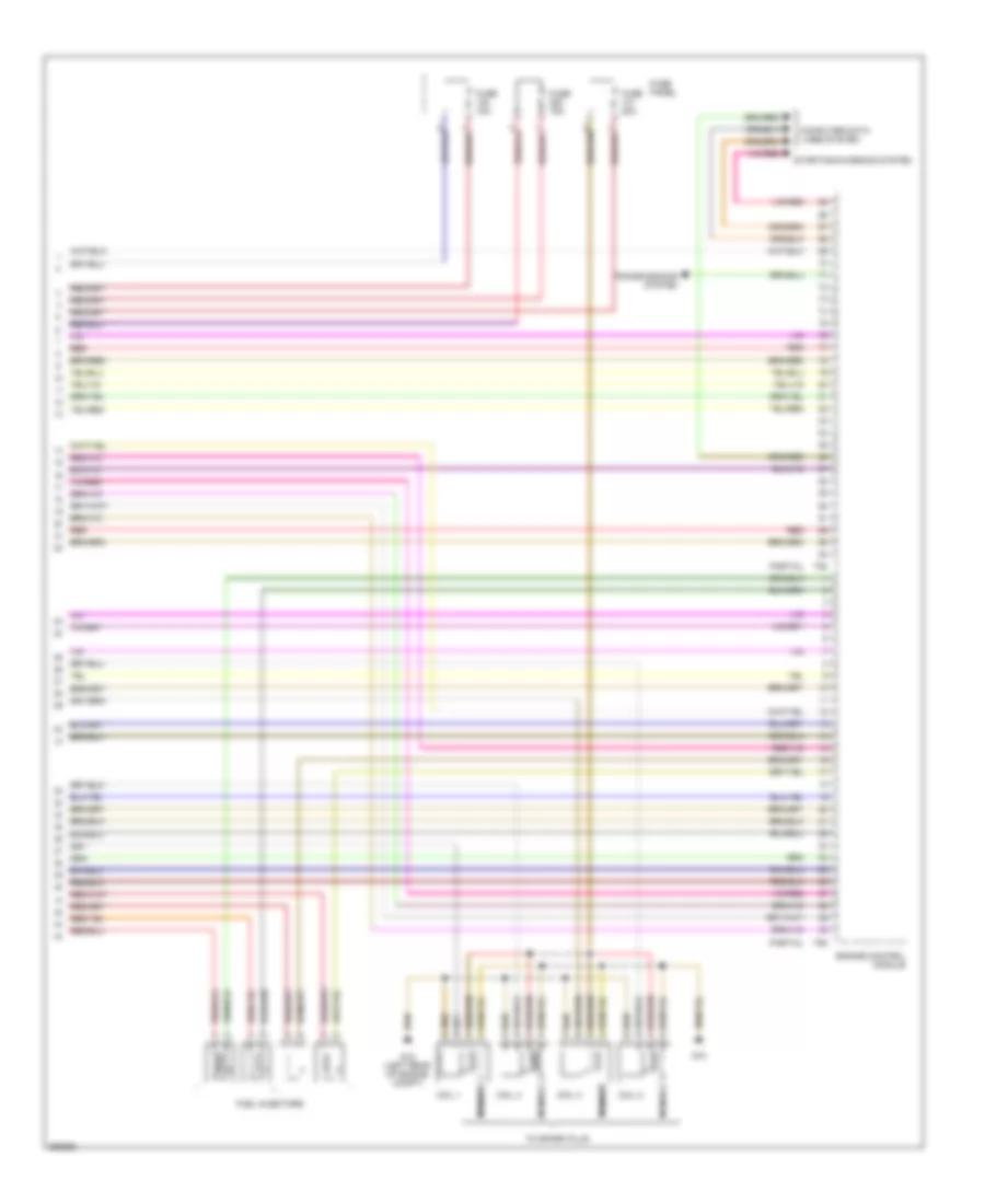
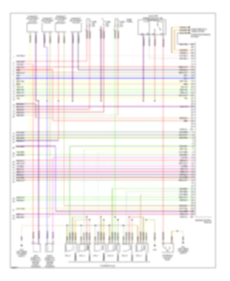
2.0L Turbo, Engine Performance Wiring Diagram (4 of 4) for Audi A4 Quattro 2007
 https://portal-diagnostov.com/license.html
Automotive Electricians Portal FZCO
Automotive Electricians Portal FZCO
https://portal-diagnostov.com/license.html
https://portal-diagnostov.com/license.html
Automotive Electricians Portal FZCO
Automotive Electricians Portal FZCOList of elements for 2.0L Turbo, Engine Performance Wiring Diagram (4 of 4) for Audi A4 Quattro 2007:
- Coil 1
- Coil 2
- Coil 3
- Coil 4
- Computer data lines system
- Engine control module
- Fuel injectors
- Fuse 15a
- Fuse 20a
- Fuse panel
- G12 (left rear of engine compt)
- G18
- Nca
- Partial
- Red
- Starting/charging system
- T60
- T94
- To spark plug
- Transmissions system
3.2L
3.2L, Engine Performance Wiring Diagram (1 of 4) for Audi A4 Quattro 2007
 https://portal-diagnostov.com/license.html
Automotive Electricians Portal FZCO
Automotive Electricians Portal FZCO
https://portal-diagnostov.com/license.html
https://portal-diagnostov.com/license.html
Automotive Electricians Portal FZCO
Automotive Electricians Portal FZCOList of elements for 3.2L, Engine Performance Wiring Diagram (1 of 4) for Audi A4 Quattro 2007:
- (left rear of engine compt) g12
- 14a
- Brake- light switch
- Clutch pedal switch
- Comfort system central control module
- Cooling fans system
- Cruise control system
- Engine control module
- Except convertible
- Fuse 10a
- Fuse 15a
- Fuse panel
- Fuse/ relay panel
- Heated oxygen sensor
- Heated oxygen sensor 2
- Hot at all times
- Hot in run or start
- Intake manifold tuning (imt) valve position sensor
- Nca
- Oxygen sensor
- Oxygen sensor 2
- Partial
- Power tops system
- Red
- Starting/ charging system
- Starting/charging system
- T12h
- T94
- Throttle position (tp) & accelerator pedal position (app) sensors
- Transmission system
- Transmissions system
3.2L, Engine Performance Wiring Diagram (2 of 4) for Audi A4 Quattro 2007
 https://portal-diagnostov.com/license.html
Automotive Electricians Portal FZCO
Automotive Electricians Portal FZCO
https://portal-diagnostov.com/license.html
https://portal-diagnostov.com/license.html
Automotive Electricians Portal FZCO
Automotive Electricians Portal FZCOList of elements for 3.2L, Engine Performance Wiring Diagram (2 of 4) for Audi A4 Quattro 2007:
- Camshaft position sensor
- Camshaft position sensor 2
- Camshaft position sensor 3
- Camshaft position sensor 4
- Control module cooling fan
- Engine coolant temperature (ect) sensor
- Engine speed (rpm) sensor
- Evaporative emission (evap) canister purge regulator valve
- Fuel metering valve
- Fuel pressure sensor
- G12 (left rear of engine compt)
- Intake air temperature sensor
- Intake manifold change-over valve
- Intake manifold runner control (imrc) valve
- Intake manifold runner position sensor
- Intake manifold runner position sensor 2
- Knock sensor (ks) 1
- Knock sensor (ks) 2
- Leak detection pump (ldp)
- Low fuel pressure sensor
- Nca
3.2L, Engine Performance Wiring Diagram (3 of 4) for Audi A4 Quattro 2007
 https://portal-diagnostov.com/license.html
Automotive Electricians Portal FZCO
Automotive Electricians Portal FZCO
https://portal-diagnostov.com/license.html
https://portal-diagnostov.com/license.html
Automotive Electricians Portal FZCO
Automotive Electricians Portal FZCOList of elements for 3.2L, Engine Performance Wiring Diagram (3 of 4) for Audi A4 Quattro 2007:
- (not used)
- (right "b" pillar) g78
- E-box relay panel
- Engine control module
- Fuel injectors
- Fuel pump control module
- Fuel pump motor
- Fuse 150a
- Fuse 20a
- Fuse panel
- Hot at all times
- Main fuse
- Partial
- Red
- T60
- Throttle valve control module
- Transmissions system
3.2L, Engine Performance Wiring Diagram (4 of 4) for Audi A4 Quattro 2007
 https://portal-diagnostov.com/license.html
Automotive Electricians Portal FZCO
Automotive Electricians Portal FZCO
https://portal-diagnostov.com/license.html
https://portal-diagnostov.com/license.html
Automotive Electricians Portal FZCO
Automotive Electricians Portal FZCOList of elements for 3.2L, Engine Performance Wiring Diagram (4 of 4) for Audi A4 Quattro 2007:
- After-run coolant pump
- Auxiliary engine coolant (ec) pump relay
- Camshaft adjustment valve 1
- Camshaft adjustment valve 1 (exhaust)
- Camshaft adjustment valve 2
- Camshaft adjustment valve 2 (exhaust)
- Coil 1
- Coil 2
- Coil 3
- Coil 4
- Coil 5
- Coil 6
- Computer data lines system
- Engine control module
- Fuse 15a
- Fuse 20a
- Fuse panel
- G12 (left rear of engine compt)
- G19
- Left electro- hydraulic engine mount solenoid
- Nca
- Partial
- Red
- Right electro- hydraulic engine mount solenoid
- Starting/charging system
- T60
- T94
- To spark plug

 Čeština
 Dansk
Dansk Deutsch
 Ελληνικά
 English
 English
 Español
 Suomi
Suomi Français
 Français
 עברית
עברית Hrvatski
 Magyar
 Italiano
 한국어
한국어 Nederlands
 Polski
 Português
 Português
 Română
 Русский
 Slovenčina
 Slovenščina
 Svenska
 Türkçe
 中文 (中国)
