ENGINE PERFORMANCE
2.7L TURBO
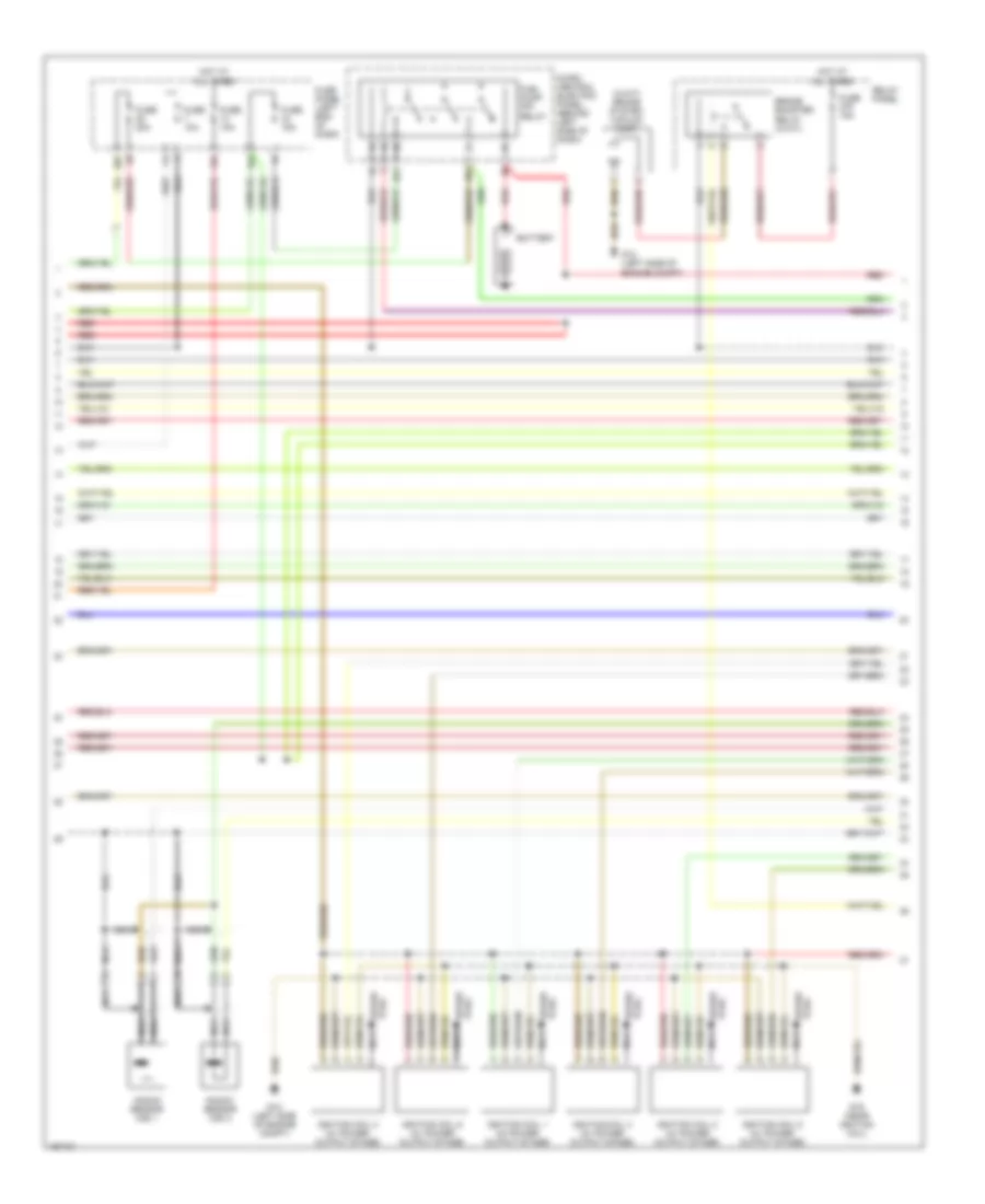
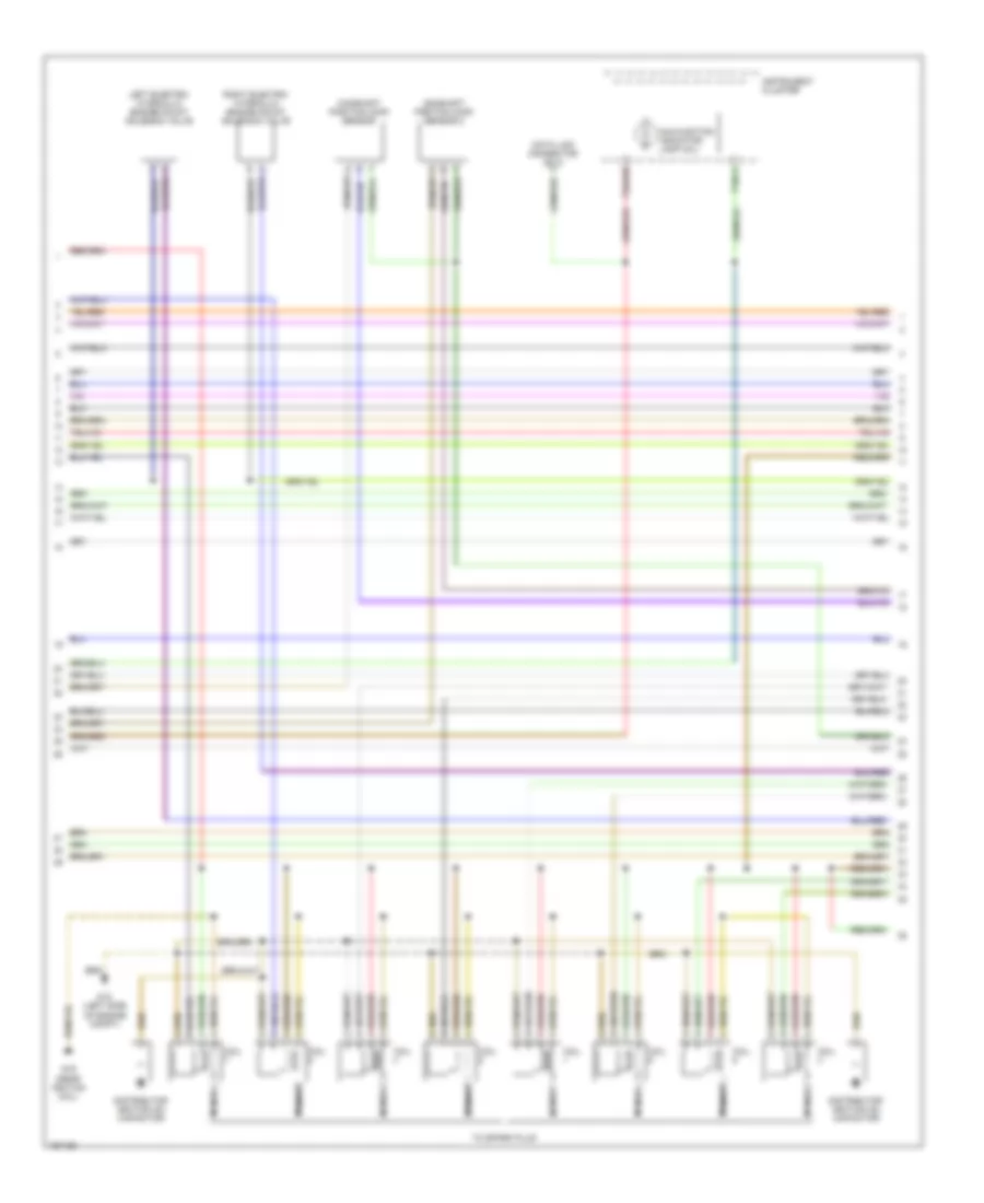
2.7L Turbo, Engine Performance Wiring Diagram (1 of 3) for Audi A6 Quattro 2003
 https://portal-diagnostov.com/license.html
Automotive Electricians Portal FZCO
Automotive Electricians Portal FZCO
https://portal-diagnostov.com/license.html
https://portal-diagnostov.com/license.html
Automotive Electricians Portal FZCO
Automotive Electricians Portal FZCO
List of elements for 2.7L Turbo, Engine Performance Wiring Diagram (1 of 3) for Audi A6 Quattro 2003:
- (left side of dash)
- (left side of engine compt) g12
- 13a
- 3-fold relay panel
- 32a
- A/c system
- Brake booster relay (a/t)
- Brake system vacuum pump
- Brake- light switch (on brake pedal support bracket)
- Clutch vacuum vent valve switch (m/t) (above clutch pedal)
- Computer data lines system
- Cruise control system
- Fuse 10a
- Fuse 15a
- Fuse 20a
- Fuse 40a
- Fuse panel
- G12 (left side of engine compt)
- Heated oxygen sensor (ho2s) 1 (behind 3-way catalytic converter)
- Heated oxygen sensor (ho2s) 1 (right side of eng, below manifold)
- Heated oxygen sensor (ho2s) 2 (behind 3-way catalytic converter)
- Heated oxygen sensor (ho2s) 2 (left side of eng, below manifold)
- Hot at all times
- Ignition switch
- Left i/p relay panel
- Mass airflow (maf) sensor (in air cleaner assembly)
- Motronic engine control module (ecm) (in electronic box, left side of fresh air plenum)
- Nca
- Off
- Pins 7 & 8 not used
- Red
- Run
- Secondary air injection (air) pump motor
- Secondary air injection (air) pump relay
- Start
- Throttle position (tp) sensor/accelerator pedal position sensor (above accelerator pedal, on bracket)
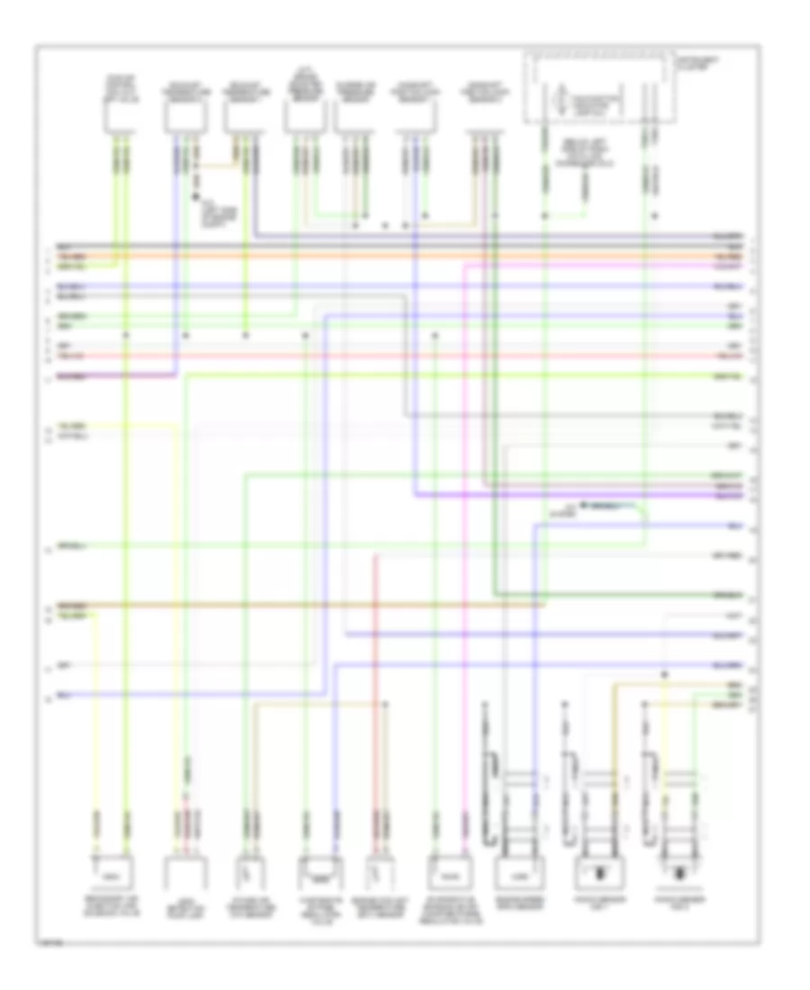
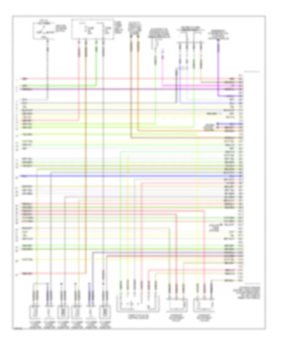
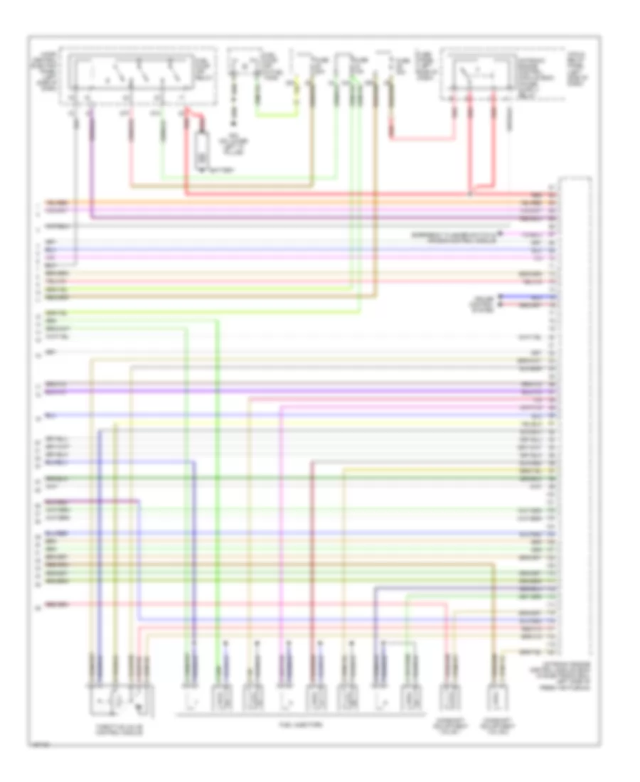
2.7L Turbo, Engine Performance Wiring Diagram (2 of 3) for Audi A6 Quattro 2003
 https://portal-diagnostov.com/license.html
Automotive Electricians Portal FZCO
Automotive Electricians Portal FZCO
https://portal-diagnostov.com/license.html
https://portal-diagnostov.com/license.html
Automotive Electricians Portal FZCO
Automotive Electricians Portal FZCOList of elements for 2.7L Turbo, Engine Performance Wiring Diagram (2 of 3) for Audi A6 Quattro 2003:
- (a/t) brake booster pressure sensor
- (mil)
- A/c system
- Camshaft position (cmp) sensor 1
- Camshaft position (cmp) sensor 2
- Charge air pressure sensor
- Engine coolant temperature (ect) sensor
- Engine speed (rpm) sensor
- Evaporative emission (evap) canister purge regulator valve
- Exhaust temperature sensor 1
- Exhaust temperature sensor 2
- G12 (left side of engine compt)
- Idle air control (iac) cut- off valve
- Instrument cluster
- Intake air temperature (iat) sensor
- Knock sensor (ks) 1
- Knock sensor (ks) 2
- Leak detection pump (ldp)
- Malfunction indicator lamp
- Nca
- Secondary air injection (air) solenoid valve
- T32/11
- T32/3
- T32a/28
- Wastegate bypass regulator valve
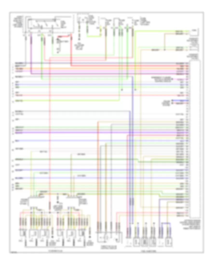
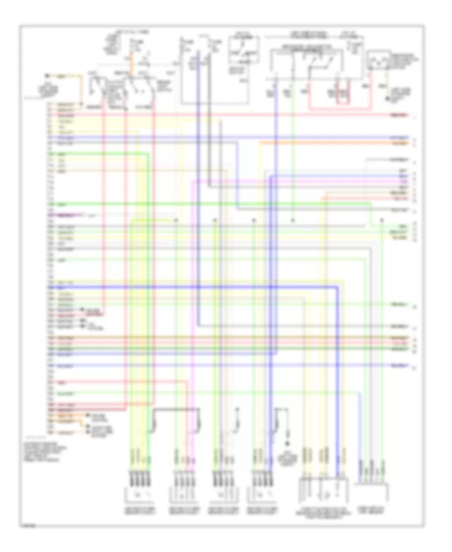
2.7L Turbo, Engine Performance Wiring Diagram (3 of 3) for Audi A6 Quattro 2003
 https://portal-diagnostov.com/license.html
Automotive Electricians Portal FZCO
Automotive Electricians Portal FZCO
https://portal-diagnostov.com/license.html
https://portal-diagnostov.com/license.html
Automotive Electricians Portal FZCO
Automotive Electricians Portal FZCOList of elements for 2.7L Turbo, Engine Performance Wiring Diagram (3 of 3) for Audi A6 Quattro 2003:
- (left side of engine compt)
- 87a
- 87f
- Battery
- Camshaft adjustment valve 1
- Camshaft adjustment valve 2
- Coil
- Cruise control system
- Emergency flasher switch & air bag control module
- Fuel injectors
- Fuel pump (fp) (in fuel tank)
- Fuel pump (fp) relay
- Fuse 15a
- Fuse 20a
- Fuse panel (left end of dash)
- G12
- G18 (on eng block)
- G44 (on lower left "a" pillar)
- Micro central electric panel (left side of dash)
- Motronic engine control module (ecm) (in electronic box, left side of fresh air plenum)
- Nca
- Power output stage 1
- Power output stage 2
- Red
- T3ba
- T3bb
- T4af
- T4ag
- Throttle valve control module
- To spark plug
3.0L
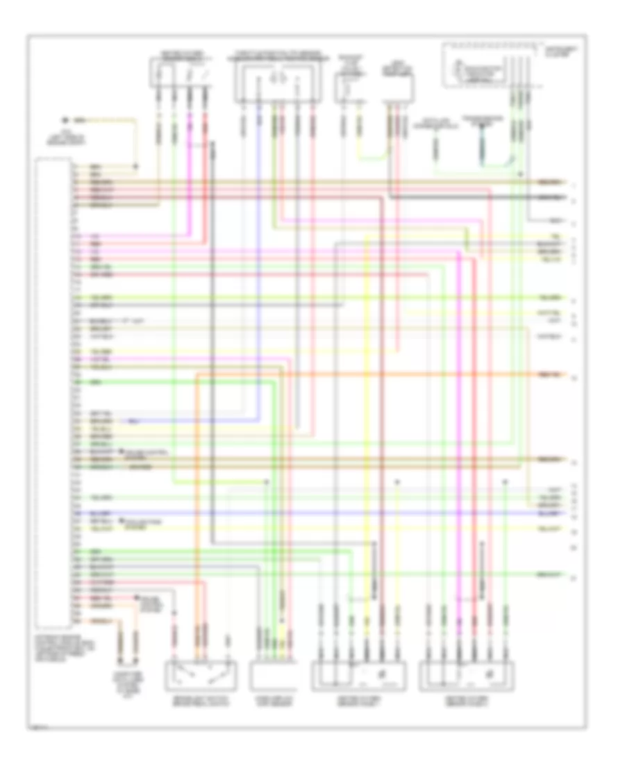
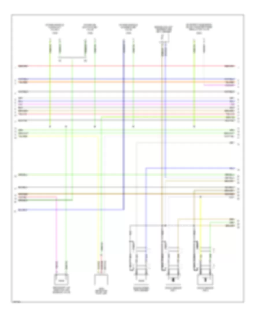
3.0L, Engine Performance Wiring Diagram (1 of 4) for Audi A6 Quattro 2003
 https://portal-diagnostov.com/license.html
Automotive Electricians Portal FZCO
Automotive Electricians Portal FZCO
https://portal-diagnostov.com/license.html
https://portal-diagnostov.com/license.html
Automotive Electricians Portal FZCO
Automotive Electricians Portal FZCOList of elements for 3.0L, Engine Performance Wiring Diagram (1 of 4) for Audi A6 Quattro 2003:
- Brakelight switch/ brake pedal switch
- Computer data lines system (w/ base a/t)
- Cooling fans system
- Cruise control system
- Data link connector (dlc)
- Exhaust flap valve 1 (w/ fwd)
- G12 (left side of engine compt)
- Heated oxygen sensor (ho2s) 1
- Heated oxygen sensor (ho2s) 2
- Heated oxygen sensor (o2s) 2
- Instrument cluster
- Leak detection pump (ldp)
- Malfunction indicator lamp (mil)
- Mass airflow (maf) sensor
- Motronic engine control module (ecm) in electronic box, on leftside of fresh air plenum)
- Nca
- Red
- T32/1
- T32/11
- T32a/28
- Throttle position (tp) sensor/ accelerator pedal position sensor
- Transmissions system
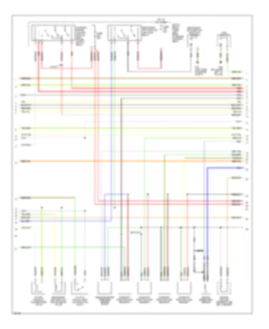
3.0L, Engine Performance Wiring Diagram (2 of 4) for Audi A6 Quattro 2003
 https://portal-diagnostov.com/license.html
Automotive Electricians Portal FZCO
Automotive Electricians Portal FZCO
https://portal-diagnostov.com/license.html
https://portal-diagnostov.com/license.html
Automotive Electricians Portal FZCO
Automotive Electricians Portal FZCOList of elements for 3.0L, Engine Performance Wiring Diagram (2 of 4) for Audi A6 Quattro 2003:
- (w/a/t)
- 3-fold relay panel (left rear of engine compart- ment)
- Brake booster pressure sensor (w/a/t)
- Camshaft position (cmp) sensor 1
- Camshaft position (cmp) sensor 2
- Camshaft position (cmp) sensor 3
- Camshaft position (cmp) sensor 4
- Clutch vacuum vent valve switch (w/m/t)
- Engine coolant temperature (ect) sensor
- Engine speed (rpm) sensor
- Fuel pump (fp)
- Fuse 15a
- Fuse 40a
- G12 (left side of engine compt)
- G44 (on lower left "a" pillar)
- Hot at all times
- Intake manifold change-over valve
- Nca
- Red
- Secondary air injection (air) pump motor
- Secondary air injection (air) pump relay
- Secondary air injection (air) solenoid valve
3.0L, Engine Performance Wiring Diagram (3 of 4) for Audi A6 Quattro 2003
 https://portal-diagnostov.com/license.html
Automotive Electricians Portal FZCO
Automotive Electricians Portal FZCO
https://portal-diagnostov.com/license.html
https://portal-diagnostov.com/license.html
Automotive Electricians Portal FZCO
Automotive Electricians Portal FZCOList of elements for 3.0L, Engine Performance Wiring Diagram (3 of 4) for Audi A6 Quattro 2003:
- (w/a/t) brake system vacuum pump
- 13a
- 28a
- 34a
- 87a
- 87f
- Battery
- Brake booster relay (w/a/t)
- Fuel pump (fp) relay
- Fuse 10a
- Fuse 15a
- Fuse 20a
- Fuse panel (left end of dash)
- G12 (left side of engine compt)
- G19 (near ignition coil)
- Hot at all times
- Ignition coil 1 (w/ power output stage)
- Ignition coil 2 (w/ power output stage)
- Ignition coil 3 (w/ power output stage)
- Ignition coil 4 (w/ power output stage)
- Ignition coil 5 (w/ power output stage)
- Ignition coil 6 (w/ power output stage)
- Knock sensor (ks) 1
- Knock sensor (ks) 2
- Micro central electric panel (behind left side of dash)
- Nca
- Plug spark
- Red
- Relay panel
- Spark plug
3.0L, Engine Performance Wiring Diagram (4 of 4) for Audi A6 Quattro 2003
 https://portal-diagnostov.com/license.html
Automotive Electricians Portal FZCO
Automotive Electricians Portal FZCO
https://portal-diagnostov.com/license.html
https://portal-diagnostov.com/license.html
Automotive Electricians Portal FZCO
Automotive Electricians Portal FZCOList of elements for 3.0L, Engine Performance Wiring Diagram (4 of 4) for Audi A6 Quattro 2003:
- (w/ multi- tronic a/t) computer data lines system
- 29a
- 32a
- Camshaft adjustment valve 1
- Camshaft adjustment valve 2
- Cooling fans system
- Cruise control system
- Cylinder 1 fuel injector
- Cylinder 2 fuel injector
- Cylinder 3 fuel injector
- Cylinder 4 fuel injector
- Cylinder 5 fuel injector
- Cylinder 6 fuel injector
- Emergency flasher switch & air bag control module
- Evaporative emission (evap) canister purge regulator valve
- Fuse 20a
- Fuse panel (left end of dash)
- Heated oxygen sensor (o2s) 1
- Hot at all times
- Ignition/ starter switch
- Motronic engine control module (ecm) (in electronic box, on left side of fresh air plenum)
- Nca
- Off
- Red
- Run
- Start
- Throttle valve control module
4.2L
4.2L, Engine Performance Wiring Diagram (1 of 4) for Audi A6 Quattro 2003
 https://portal-diagnostov.com/license.html
Automotive Electricians Portal FZCO
Automotive Electricians Portal FZCO
https://portal-diagnostov.com/license.html
https://portal-diagnostov.com/license.html
Automotive Electricians Portal FZCO
Automotive Electricians Portal FZCOList of elements for 4.2L, Engine Performance Wiring Diagram (1 of 4) for Audi A6 Quattro 2003:
- (left side of dash)
- (left side of dash) 3-fold relay panel
- (left side of engine compt) g12
- 13a
- 32a
- A/c system
- Brake- light switch
- Clutch vacuum vent valve switch (m/t)
- Computer data lines system
- Cruise control
- Fuse 10a
- Fuse 20a
- Fuse 40a
- Fuse panel
- G12 (left side of engine compt)
- Heated oxygen sensor (ho2s) 1
- Heated oxygen sensor (ho2s) 2
- Hot at all times
- Ignition switch
- Mass airflow (maf) sensor
- Motronic engine control module (ecm) (in electronic box, left side of fresh air plenum)
- Nca
- Off
- Red
- Run
- Secondary air injection (air) pump motor
- Secondary air injection (air) pump relay
- Start
- Throttle position (tp) sensor/accelerator pedal position sensor 2
4.2L, Engine Performance Wiring Diagram (2 of 4) for Audi A6 Quattro 2003
 https://portal-diagnostov.com/license.html
Automotive Electricians Portal FZCO
Automotive Electricians Portal FZCO
https://portal-diagnostov.com/license.html
https://portal-diagnostov.com/license.html
Automotive Electricians Portal FZCO
Automotive Electricians Portal FZCOList of elements for 4.2L, Engine Performance Wiring Diagram (2 of 4) for Audi A6 Quattro 2003:
- Engine coolant temperature (ect) sensor
- Engine speed (rpm) sensor
- Evaporative emission (evap) canister purge regulator valve
- Intake air switch-over valve
- Intake manifold change-over valve
- Intake manifold tuning (imt) valve 2
- Knock sensor (ks) 1
- Knock sensor (ks) 2
- Leak detection pump (ldp)
- Nca
- Secondary air injection (air) solenoid valve
4.2L, Engine Performance Wiring Diagram (3 of 4) for Audi A6 Quattro 2003
 https://portal-diagnostov.com/license.html
Automotive Electricians Portal FZCO
Automotive Electricians Portal FZCO
https://portal-diagnostov.com/license.html
https://portal-diagnostov.com/license.html
Automotive Electricians Portal FZCO
Automotive Electricians Portal FZCOList of elements for 4.2L, Engine Performance Wiring Diagram (3 of 4) for Audi A6 Quattro 2003:
- (mil)
- Camshaft position (cmp) sensor
- Camshaft position (cmp) sensor 2
- Coil
- Data link connector (dlc)
- Distributor ignition (di) capacitor
- G12 (left side of engine compt)
- G19 (near ignition coil)
- Instrument cluster
- Left electro- hydraulic engine mount solenoid valve
- Malfunction indicator lamp
- Nca
- Right electro- hydraulic engine mount solenoid valve
- T32/11
- T32a/28
- To spark plug
4.2L, Engine Performance Wiring Diagram (4 of 4) for Audi A6 Quattro 2003
 https://portal-diagnostov.com/license.html
Automotive Electricians Portal FZCO
Automotive Electricians Portal FZCO
https://portal-diagnostov.com/license.html
https://portal-diagnostov.com/license.html
Automotive Electricians Portal FZCO
Automotive Electricians Portal FZCOList of elements for 4.2L, Engine Performance Wiring Diagram (4 of 4) for Audi A6 Quattro 2003:
- 3-fold relay panel (left side of dash)
- 87a
- 87f
- Battery
- Camshaft adjustment valve 1
- Camshaft adjustment valve 2
- Cruise control system
- Emergency flasher switch & air bag control module
- Fuel injectors
- Fuel pump (fp) (in fuel tank)
- Fuel pump (fp) relay
- Fuse 15a
- Fuse 20a
- Fuse 30a
- Fuse panel (left side of dash)
- G44 (on lower left "a" pillar)
- Micro central electric panel (left side of dash)
- Motronic engine control module (ecm) (in electronic box, left side of fresh air plenum)
- Red
- Throttle valve control module

 Čeština
 Dansk
Dansk Deutsch
 Ελληνικά
 English
 English
 Español
 Suomi
Suomi Français
 Français
 עברית
עברית Hrvatski
 Magyar
 Italiano
 한국어
한국어 Nederlands
 Polski
 Português
 Português
 Română
 Русский
 Slovenčina
 Slovenščina
 Svenska
 Türkçe
 中文 (中国)
