ENGINE PERFORMANCE
3.0L SC
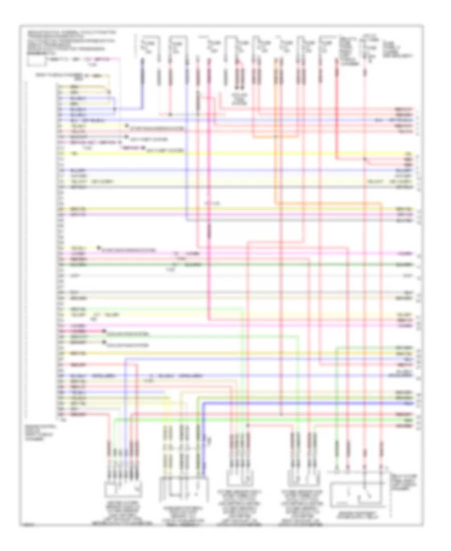
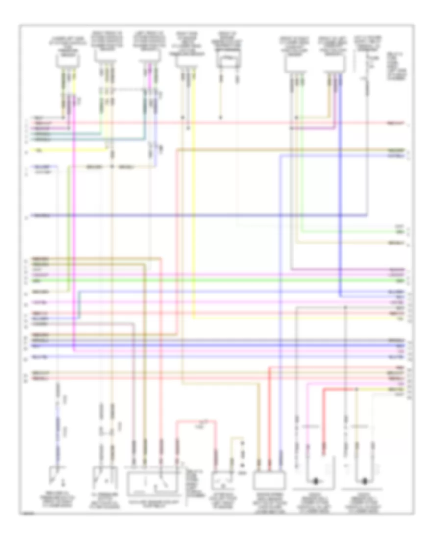
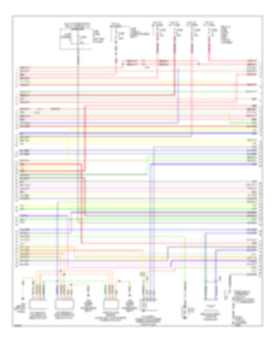
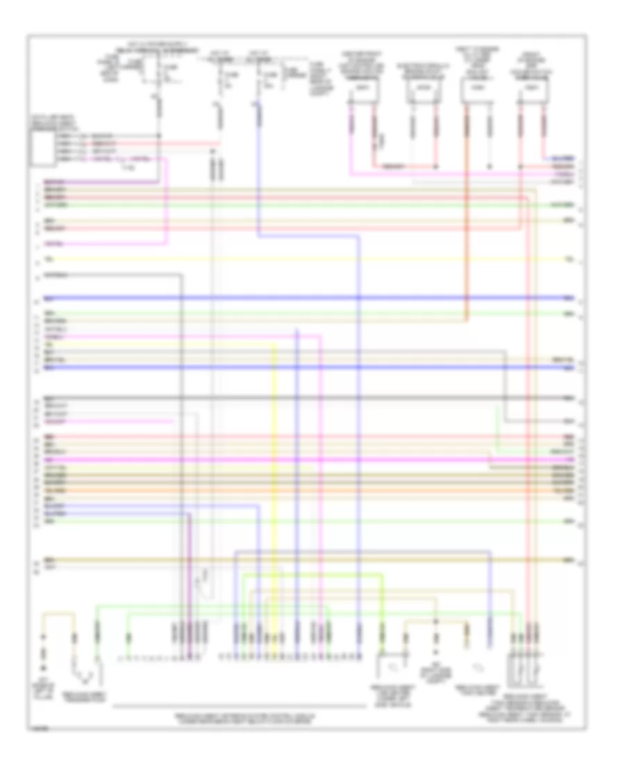
3.0L SC, Engine Performance Wiring Diagram (1 of 6) for Audi Q7 Premium Plus 2014
 https://portal-diagnostov.com/license.html
Automotive Electricians Portal FZCO
Automotive Electricians Portal FZCO
https://portal-diagnostov.com/license.html
https://portal-diagnostov.com/license.html
Automotive Electricians Portal FZCO
Automotive Electricians Portal FZCO
List of elements for 3.0L SC, Engine Performance Wiring Diagram (1 of 6) for Audi Q7 Premium Plus 2014:
- (backup switch: integral to multi-function transmission range switch multi-function transmission range switch: side of transmission) backup & multi-function transmission range switch
- (right exhaust, on catalytic converter)
- (right plenum chamber) g609
- 10a
- 13a
- 14a
- 15a
- 17a
- Accelerator pedal position (app) sensor 1 & 2 (top of accelerator pedal assembly)
- Anti-theft system
- Cooling fans system
- Engine control module (right plenum chamber)
- Fuse 10a
- Fuse 150a
- Fuse 15a
- Fuse 20a
- Fuse 5a
- Fuse panel d (under driver's seat)
- Heated oxygen sensor (ho2s) 2 & oxygen sensor (o2s) heater 2 (left exhaust pipe, before catalytic converter)
- Hot at all times
- Nca
- Oxygen sensor (02s) 2 after three way catalytic (twc) converter & heated oxygen sensor 2 after catalytic converter (left exhaust, on catalytic converter)
- Oxygen sensor (o2s) after three way catalytic (twc) converter & heated oxygen sensor 1 after catalytic converter
- Red
- Relay & fuse panel e-box (left plenum chamber)
- Starting/charging system
- T10c
- T10e
- T10m
- T14h
- T17d
- T6k
- T94
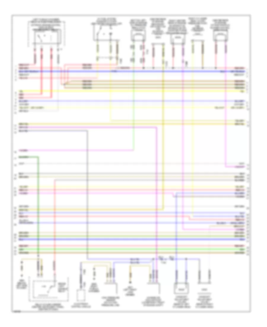
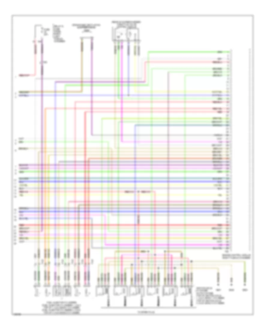
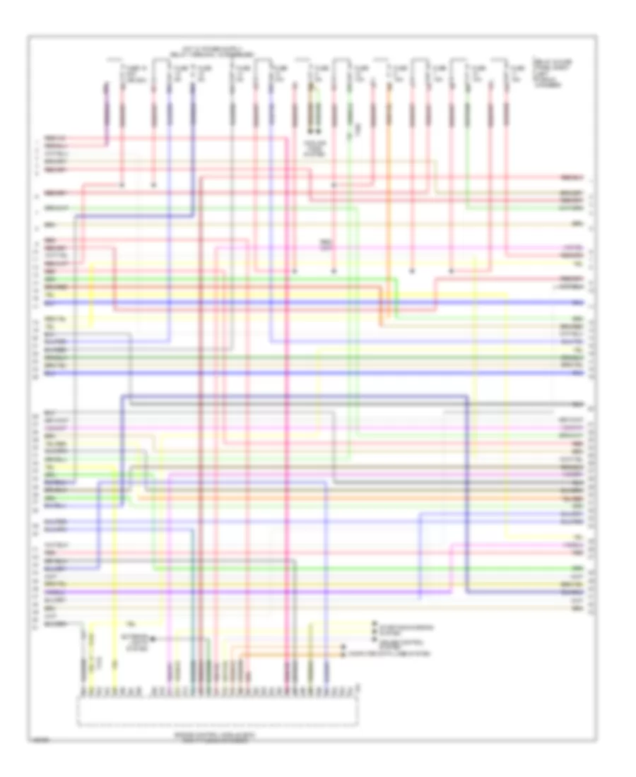
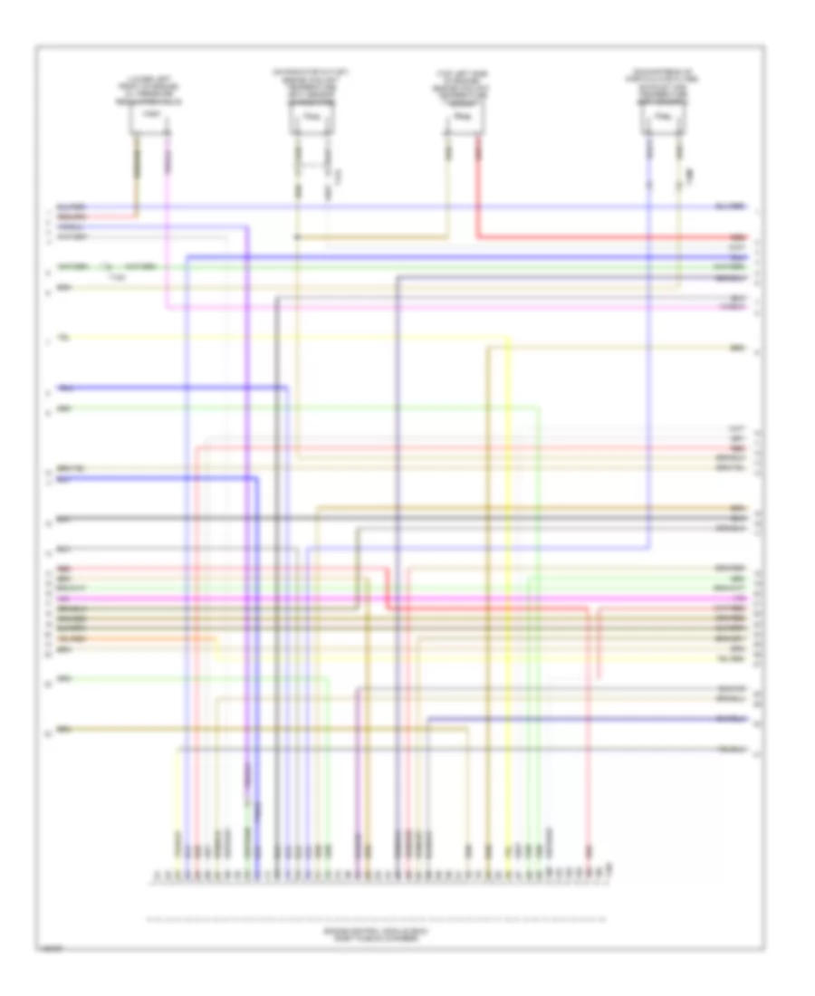
3.0L SC, Engine Performance Wiring Diagram (2 of 6) for Audi Q7 Premium Plus 2014
 https://portal-diagnostov.com/license.html
Automotive Electricians Portal FZCO
Automotive Electricians Portal FZCO
https://portal-diagnostov.com/license.html
https://portal-diagnostov.com/license.html
Automotive Electricians Portal FZCO
Automotive Electricians Portal FZCOList of elements for 3.0L SC, Engine Performance Wiring Diagram (2 of 6) for Audi Q7 Premium Plus 2014:
- (bottom left side of engine) oil pressure regulation valve
- (center rear of engine) intake manifold runner control (imrc) valve
- (center rear of engine) secondary air injection (air) solenoid valve
- (left plenum chamber) relay & fuse panel e-box
- (rear of right cylinder head)
- (right center rear of engine) evaporative emission (evap) canister purge regulator valve 1
- (right cylinder head, in high pressure pump) fuel metering valve 1
- (w/ fuel system diagnostic pump) leak detection pump (ldp)
- Brake light disable relay
- Camshaft adjustment valve 1
- Camshaft adjustment valve 2 (rear of left cylinder head)
- Charge air cooling pump (lower right front of engine compt)
- Climatronic control module
- G609 (right plenum chamber)
- G664 (behind left side of dash)
- G671 (left front long member)
- High pressure sensor (on a/c high pressure line)
- Red
- Relay & fuse carrier (center instrument panel) (center of dash)
- T10d
- T10e
- T10m
- T14l
- T16d
- T17d
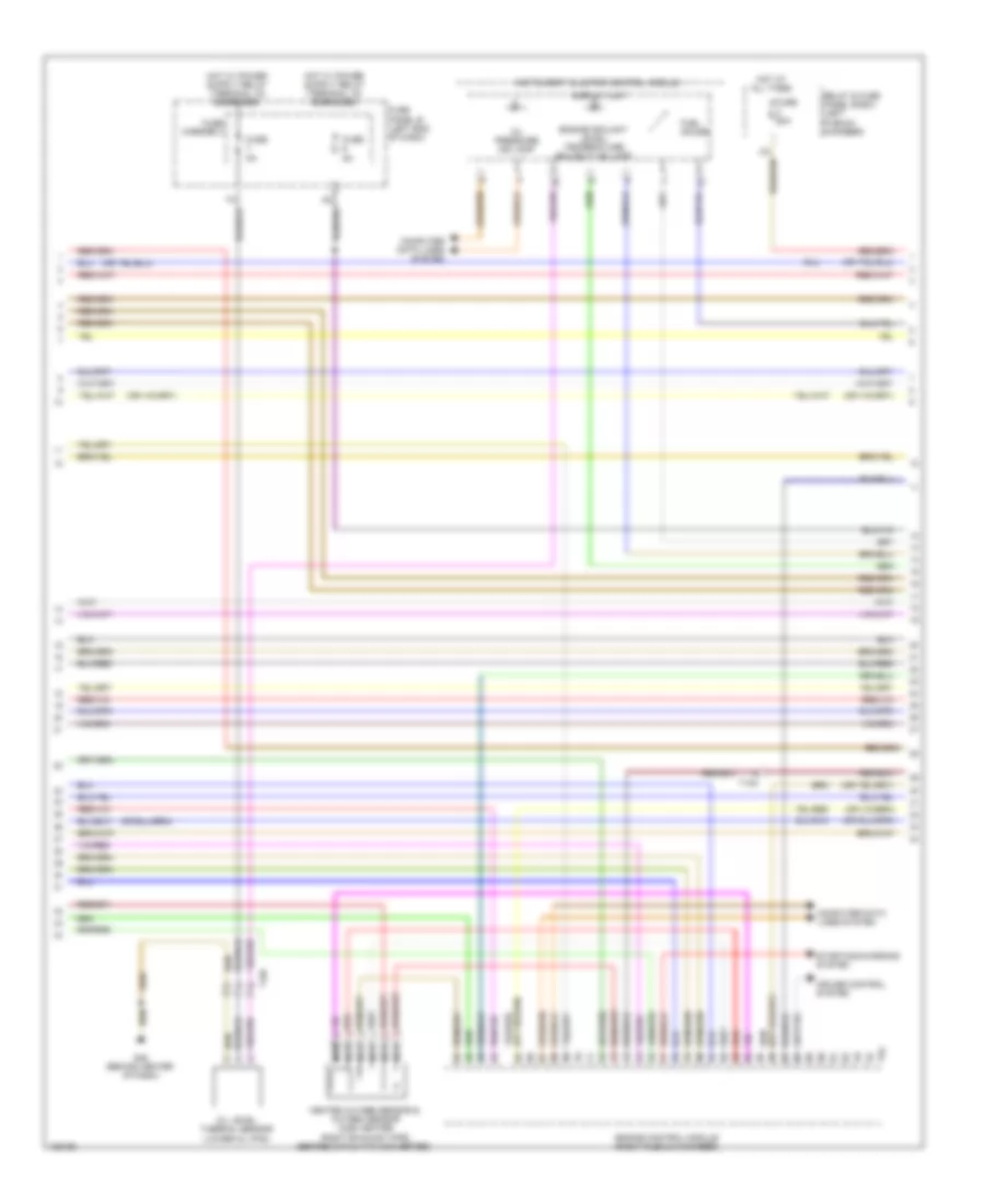
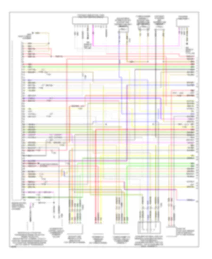
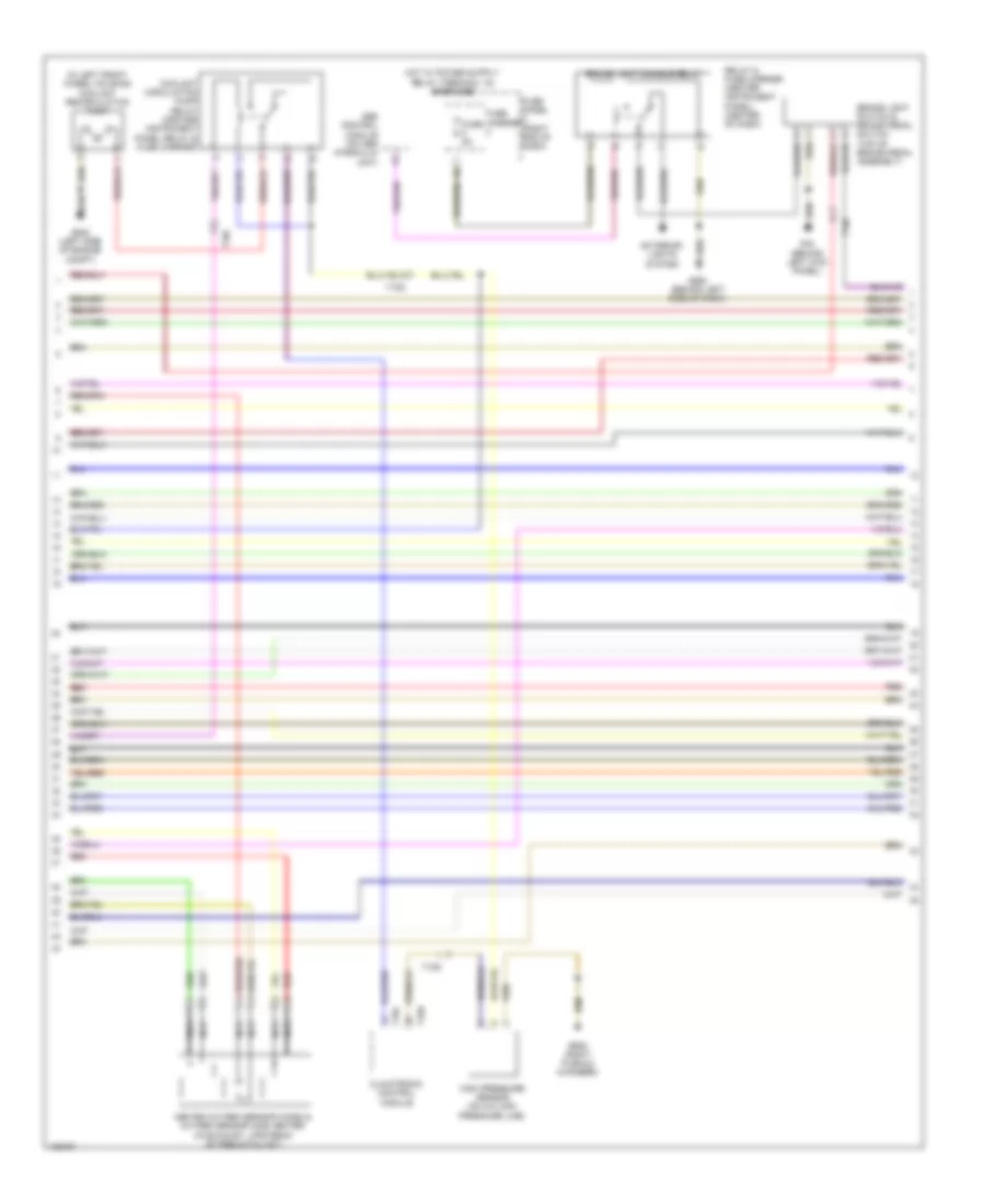
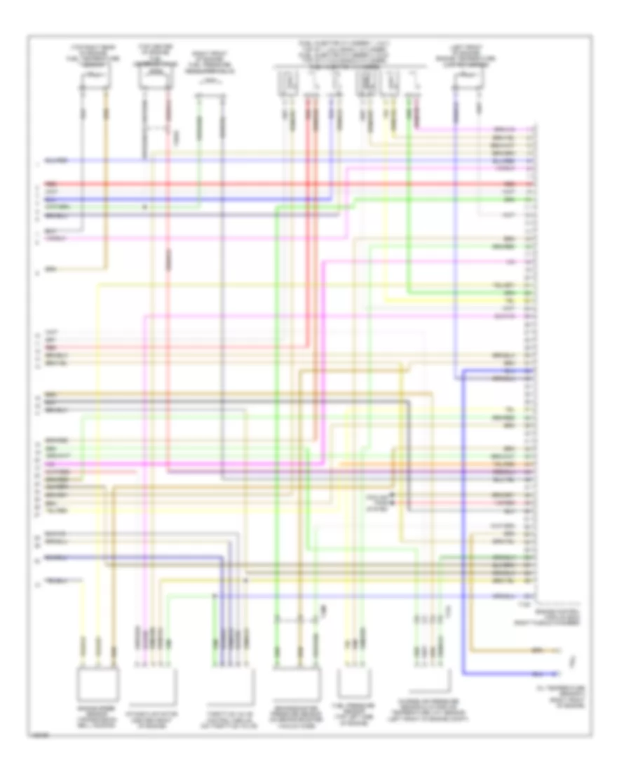
3.0L SC, Engine Performance Wiring Diagram (3 of 6) for Audi Q7 Premium Plus 2014
 https://portal-diagnostov.com/license.html
Automotive Electricians Portal FZCO
Automotive Electricians Portal FZCO
https://portal-diagnostov.com/license.html
https://portal-diagnostov.com/license.html
Automotive Electricians Portal FZCO
Automotive Electricians Portal FZCOList of elements for 3.0L SC, Engine Performance Wiring Diagram (3 of 6) for Audi Q7 Premium Plus 2014:
- Computer data lines system
- Cruise control system
- Display unit
- Engine control module (right plenum chamber)
- Engine coolant level/ temperature (ecl/ect) ind lamp
- Fuel gauge
- Fuse 50a
- Fuse 5a
- Fuse carrier 3
- Fuse panel b (left end of dash)
- G45 (behind center of dash)
- Heated oxygen sensor & oxygen sensor (o2s) heater (right exhaust pipe, before catalytic converter)
- Hot at all times
- Instrument cluster control module
- Nca
- Oil level thermal sensor (lower oil pan)
- Oil pressure ind lamp
- Red
- Relay & fuse panel e-box (left plenum chamber)
- Starting/charging system
- T10c
- T10f
- T94
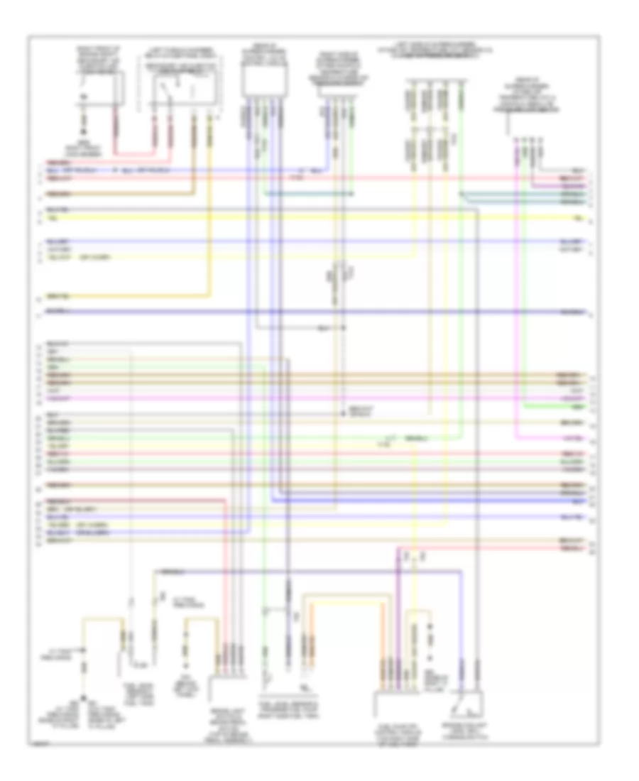
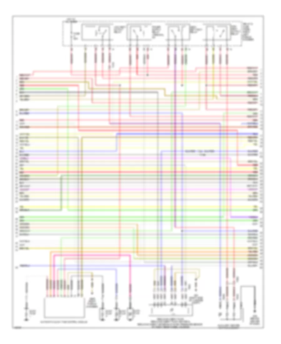
3.0L SC, Engine Performance Wiring Diagram (4 of 6) for Audi Q7 Premium Plus 2014
 https://portal-diagnostov.com/license.html
Automotive Electricians Portal FZCO
Automotive Electricians Portal FZCO
https://portal-diagnostov.com/license.html
https://portal-diagnostov.com/license.html
Automotive Electricians Portal FZCO
Automotive Electricians Portal FZCOList of elements for 3.0L SC, Engine Performance Wiring Diagram (4 of 6) for Audi Q7 Premium Plus 2014:
- (left plenum chamber) relay & fuse panel e-box
- (left side of supercharger) intake air temperature (iat) sensor 2 & charge air pressure sensor 2
- (rear of supercharger) control valve control module
- (rear of supercharger) intake air temperature (iat) & manifold absolute pressure (map) sensor
- (right front of engine compt) secondary air injection (air) pump motor
- (right side of supercharger) intake manifold temperature sensor & charge air pressure sensor
- Brake light switch & brake pedal switch (top of brake pedal assembly)
- Engine coolant level (ecl) warning switch
- Fuel level sensor & transfer fuel pump (right side fuel tank)
- Fuel level sensor 2 (left side fuel tank)
- Fuel pump (fp) control module (top right side of fuel tank)
- G44 (behind left kick panel)
- G61 (w/o tank pre-wiring) (base of left "c" pillar)
- G62 (base of right "c" pillar)
- G62 (w/ tank pre-wiring) (base of right "c" pillar)
- G685 (right front long member)
- Secondary air injection (air) pump relay
- T17d
- T2k
- T5k
- W/ tank pre-wiring
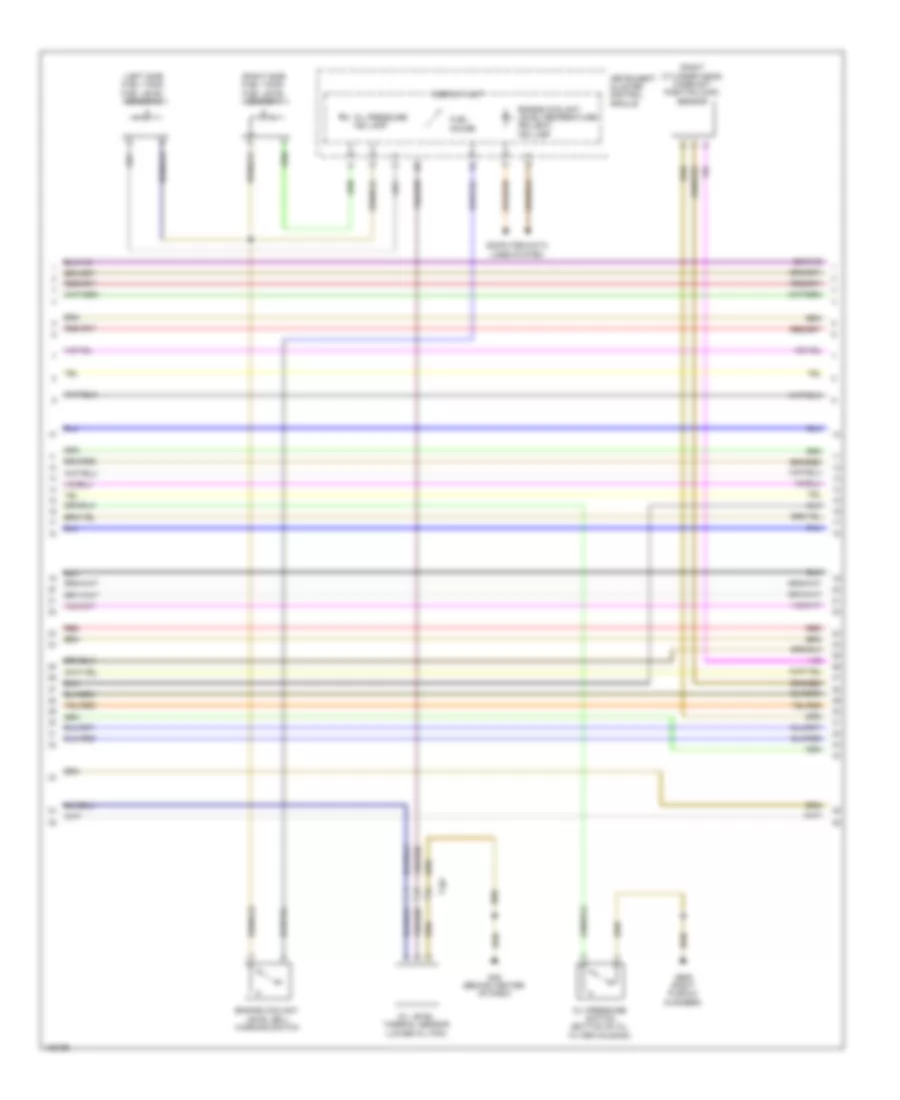
3.0L SC, Engine Performance Wiring Diagram (5 of 6) for Audi Q7 Premium Plus 2014
 https://portal-diagnostov.com/license.html
Automotive Electricians Portal FZCO
Automotive Electricians Portal FZCO
https://portal-diagnostov.com/license.html
https://portal-diagnostov.com/license.html
Automotive Electricians Portal FZCO
Automotive Electricians Portal FZCOList of elements for 3.0L SC, Engine Performance Wiring Diagram (5 of 6) for Audi Q7 Premium Plus 2014:
- (front of engine) engine coolant temperature (ect) sensor
- (front of left cylinder head) camshaft position (cmp) sensor 2
- (front of right cylinder head) camshaft position (cmp) sensor
- (left front of intake manifold) intake manifold runner position sensor 2
- (right front of intake manifold) intake manifold runner position sensor
- (right side of engine above cylinder head) low fuel pressure sensor
- (under left side of intake manifold) fuel pressure sensor
- 19a
- 19c
- 19d
- 19e
- After run coolant pump (left front of engine)
- Auxiliary engine coolant pump relay
- Engine speed (rpm) sensor (bottom of timing chain guard lower section)
- Fuse 5a
- G645
- Knock sensor (ks) 1 (under intake manifold, on right cylinder head)
- Knock sensor (ks) 2 (under intake manifold, on left cylinder head)
- Oil pressure switch (bottom of oil filter housing)
- Red
- Reduced oil pressure switch (front of right cylinder bank)
- Relay & fuse panel e-box (left plenum chamber)
- Relay & fuse panel e-box (left side of plenum chamber)
- T10m
- T114l
- T14f
- T14l
- T17d
3.0L SC, Engine Performance Wiring Diagram (6 of 6) for Audi Q7 Premium Plus 2014
 https://portal-diagnostov.com/license.html
Automotive Electricians Portal FZCO
Automotive Electricians Portal FZCO
https://portal-diagnostov.com/license.html
https://portal-diagnostov.com/license.html
Automotive Electricians Portal FZCO
Automotive Electricians Portal FZCOList of elements for 3.0L SC, Engine Performance Wiring Diagram (6 of 6) for Audi Q7 Premium Plus 2014:
- (rear of supercharger) throttle valve control module
- 16a
- Crankcase ventilation shut-off valve
- Engine control module (right plenum chamber)
- Fuel injector cylinders (fuel injector cylinders 1, 2 & 3: top of 1, 2 & 3 bank 1 cylinder) (fuel injector cylinders 4, 5 & 6: top of 4, 5 & 6 bank 2 cylinder)
- Fuse 20a
- G600
- G601
- G645
- Ignition coils w/ power output stage (top of ignition coils 1, 2 & 3: bank 1 cylinder) (top of ignition coils 4, 5 & 6: bank 2 cylinder)
- Nca
- Red
- Relay & fuse panel e-box (left plenum chamber)
- T14f
- T14l
- T60
- T6k
- To spark plug
3.0L TURBO DIESEL
3.0L Turbo Diesel, Engine Performance Wiring Diagram (1 of 9) for Audi Q7 Premium Plus 2014
 https://portal-diagnostov.com/license.html
Automotive Electricians Portal FZCO
Automotive Electricians Portal FZCO
https://portal-diagnostov.com/license.html
https://portal-diagnostov.com/license.html
Automotive Electricians Portal FZCO
Automotive Electricians Portal FZCOList of elements for 3.0L Turbo Diesel, Engine Performance Wiring Diagram (1 of 9) for Audi Q7 Premium Plus 2014:
- (base of
- (downstream of pre-catalyst) exhaust gas temperature (egt) sensor 3
- (top front of engine) egr temperature sensor
- (top right side of fuel tank) fuel pump control module
- (turbocharger assembly) exhaust gas temperature (egt) sensor 1
- Accelerator pedal position sensor & accelerator pedal position sensor 2 (accelerator pedal position sensor 1: top of accelerator pedal assembly)
- Access/start control module (underside of steering column)
- Backup & multi-function transmission range (tr) switch range (tr) switch (backup switch: integral to multi- function transmission range switch multi-function transmission range switch: side of transmission)
- Differential pressure sensor (on turbocharger)
- Engine control module (ecm) (right plenum chamber)
- Exhaust gas recirculation (egr) motor (top center of engine)
- G609 (right plenum chamber)
- G62
- G62 (base of right "c" pillar)
- Mass air flow (maf) sensor (air intake duct at filter housing)
- Nca
- Red
- Right "c" pillar)
- Starting/charging system
- T10ab
- T10c
- T10d
- T10e
- T10m
- T10d
- T14h
- T17d
- T17e
- T20e
- T91
- Transfer fuel pump
- Turbocharger (tc) control module 1 (turbocharger assembly)
3.0L Turbo Diesel, Engine Performance Wiring Diagram (2 of 9) for Audi Q7 Premium Plus 2014
 https://portal-diagnostov.com/license.html
Automotive Electricians Portal FZCO
Automotive Electricians Portal FZCO
https://portal-diagnostov.com/license.html
https://portal-diagnostov.com/license.html
Automotive Electricians Portal FZCO
Automotive Electricians Portal FZCOList of elements for 3.0L Turbo Diesel, Engine Performance Wiring Diagram (2 of 9) for Audi Q7 Premium Plus 2014:
- Automatic glow time control module
- Auxiliary heater heating element
- Fuse 60a
- G45 (behind center of dash)
- G51 (right side of luggage compt)
- G609 (right plenum chamber)
- Glow plug
- Heat setting 3 relay
- High heat output relay
- Hot at all times
- Low heat output relay
- Nca
- Red
- Reducing agent pump, reducing agent pump heater & reducing agent metering system pressure sensor (at right rear wheel housing)
- Relay & fuse panel e-box (left plenum chamber)
- T17e
- T2bg
- T2cq
- T6ar
- T8al
3.0L Turbo Diesel, Engine Performance Wiring Diagram (3 of 9) for Audi Q7 Premium Plus 2014
 https://portal-diagnostov.com/license.html
Automotive Electricians Portal FZCO
Automotive Electricians Portal FZCO
https://portal-diagnostov.com/license.html
https://portal-diagnostov.com/license.html
Automotive Electricians Portal FZCO
Automotive Electricians Portal FZCOList of elements for 3.0L Turbo Diesel, Engine Performance Wiring Diagram (3 of 9) for Audi Q7 Premium Plus 2014:
- (right plenum chamber) g609
- 17a
- Cylinder 2 combustion chamber pressure sensor & glow plug 2
- Fuse 150a
- Fuse 40a
- Fuse 5a
- Fuse 60a
- Fuse 80a
- Fuse carrier
- Fuse panel b (left end of dash)
- Fuse panel d (under driver's seat)
- G35 (under front passenger's seat)
- G44 (behind left kick panel)
- Glow plug
- Hot at all times
- Nox sensor 1 (upstream of pre-catalyst)
- Nox sensor 2 (downstream of scr catalyst)
- Particulate sensor (in exhaust, downstream of scr catalyst)
- Red
- Reduced oil pressure switch (front of right cylinder bank)
- Reducing agent injector (in exhaust)
- Relay & fuse panel e-box (left plenum chamber)
- T10c
- T10m
- T6t
3.0L Turbo Diesel, Engine Performance Wiring Diagram (4 of 9) for Audi Q7 Premium Plus 2014
 https://portal-diagnostov.com/license.html
Automotive Electricians Portal FZCO
Automotive Electricians Portal FZCO
https://portal-diagnostov.com/license.html
https://portal-diagnostov.com/license.html
Automotive Electricians Portal FZCO
Automotive Electricians Portal FZCOList of elements for 3.0L Turbo Diesel, Engine Performance Wiring Diagram (4 of 9) for Audi Q7 Premium Plus 2014:
- 10a
- 11a
- 12a
- 13a
- 14a
- 15a
- 16a
- 18a
- Computer data lines system
- Cooling fans system
- Cruise control system
- Engine control module (ecm) (right plenum chamber)
- Exterior lights system
- Fuse 10a
- Fuse 15a
- Fuse 16 20a (or 25a)
- Fuse 5a
- Red
- Relay & fuse panel e-box (left plenum chamber)
- Starting/charging system
- T10e
- T17d
- T17e
- T91
3.0L Turbo Diesel, Engine Performance Wiring Diagram (5 of 9) for Audi Q7 Premium Plus 2014
 https://portal-diagnostov.com/license.html
Automotive Electricians Portal FZCO
Automotive Electricians Portal FZCO
https://portal-diagnostov.com/license.html
https://portal-diagnostov.com/license.html
Automotive Electricians Portal FZCO
Automotive Electricians Portal FZCOList of elements for 3.0L Turbo Diesel, Engine Performance Wiring Diagram (5 of 9) for Audi Q7 Premium Plus 2014:
- (in left front wheel housing) coolant recirculation pump
- Abs control module (on abs hydraulic unit)
- Brake light disable relay
- Brake light switch & brake pedal switch (top of brake pedal assembly)
- Climatronic control module
- Coolant circulation pump relay (center instrument panel relay & fuse carrier)
- Exterior lights system
- Fuse 5a
- Fuse carrier
- Fuse panel c (right end of dash)
- G44 (behind left kick panel)
- G609 (right plenum chamber)
- G640 (left side of engine compt)
- G664 (behind left side of dash)
- Heated oxygen sensor (ho2s) & oxygen sensor (o2s) heater (in exhaust, upstream of pre-catalyst)
- High pressure sensor (on a/c high pressure line)
- Nca
- Red
- Relay & fuse carrier (center instrument panel) (center of dash)
- T10c
- T10d
- T16c
- T16d
3.0L Turbo Diesel, Engine Performance Wiring Diagram (6 of 9) for Audi Q7 Premium Plus 2014
 https://portal-diagnostov.com/license.html
Automotive Electricians Portal FZCO
Automotive Electricians Portal FZCO
https://portal-diagnostov.com/license.html
https://portal-diagnostov.com/license.html
Automotive Electricians Portal FZCO
Automotive Electricians Portal FZCOList of elements for 3.0L Turbo Diesel, Engine Performance Wiring Diagram (6 of 9) for Audi Q7 Premium Plus 2014:
- (left side fuel tank) fuel level sensor 2
- (right cylinder head) camshaft position (cmp) sensor
- (right side fuel tank) fuel level sensor 1
- Computer data lines system
- Display unit
- Engine coolant
- Engine coolant level/temperature (ecl/ect) ind lamp
- Fuel gauge
- G45 (behind center of dash)
- G609 (right plenum chamber)
- Instrument cluster control module
- Level (ecl) warning switch
- Oil level thermal sensor (lower oil pan)
- Oil pressure ind lamp
- Oil pressure switch (bottom of oil filter housing)
- Red
- T10f
3.0L Turbo Diesel, Engine Performance Wiring Diagram (7 of 9) for Audi Q7 Premium Plus 2014
 https://portal-diagnostov.com/license.html
Automotive Electricians Portal FZCO
Automotive Electricians Portal FZCO
https://portal-diagnostov.com/license.html
https://portal-diagnostov.com/license.html
Automotive Electricians Portal FZCO
Automotive Electricians Portal FZCOList of elements for 3.0L Turbo Diesel, Engine Performance Wiring Diagram (7 of 9) for Audi Q7 Premium Plus 2014:
- (center front of engine) map controlled engine cooling thermostat
- (front of engine) egr cooler switch over valve
- (next to engine oil filter) cylinder head coolant valve
- (on filler neck) reducing agent tank cap switch
- (reducing agent tank sensor: at right rear wheel housing)
- Electrohydraulic engine mount solenoid valve
- Fuse 30a
- Fuse 5a
- Fuse carrier
- Fuse panel b (left end of dash)
- Fuse panel f (right rear of luggage compt)
- G51 (right side of luggage compt)
- G77 (base of left "b" pillar)
- Hot at all times
- Nca
- Red
- Reducing agent line heater (under left side vehicle)
- Reducing agent metering system control module (under rear bench seat below floor covering)
- Reducing agent tank heater
- Reducing agent tank sensor & reducing agent temperature sensor
- Reducing agent transfer pump
- T10ab
- T17e
3.0L Turbo Diesel, Engine Performance Wiring Diagram (8 of 9) for Audi Q7 Premium Plus 2014
 https://portal-diagnostov.com/license.html
Automotive Electricians Portal FZCO
Automotive Electricians Portal FZCO
https://portal-diagnostov.com/license.html
https://portal-diagnostov.com/license.html
Automotive Electricians Portal FZCO
Automotive Electricians Portal FZCOList of elements for 3.0L Turbo Diesel, Engine Performance Wiring Diagram (8 of 9) for Audi Q7 Premium Plus 2014:
- (downstream of particulate filter) exhaust gas temperature (ect) sensor 4
- (lower left front of engine) oil pressure regulation valve
- (on radiator outlet) engine coolant temperature (ect) sensor (on radiator)
- (top left side of engine) engine coolant temperature sensor
- Engine control module (ecm) (right plenum chamber)
- Red
- T105
- T10ab
- T10m
- T17d
3.0L Turbo Diesel, Engine Performance Wiring Diagram (9 of 9) for Audi Q7 Premium Plus 2014
 https://portal-diagnostov.com/license.html
Automotive Electricians Portal FZCO
Automotive Electricians Portal FZCO
https://portal-diagnostov.com/license.html
https://portal-diagnostov.com/license.html
Automotive Electricians Portal FZCO
Automotive Electricians Portal FZCOList of elements for 3.0L Turbo Diesel, Engine Performance Wiring Diagram (9 of 9) for Audi Q7 Premium Plus 2014:
- (fuel injector cylinders 1, 2 & 3: top of 1, 2 & 3 bank 1 cylinder) (fuel injector cylinders 4, 5 & 6: top of 4, 5 & 6 bank 2 cylinder) fuel injector cylinders
- (left front of engine) engine temperature control sensor
- (right front of engine) fuel pressure regulator valve
- (top center of engine) fuel metering valve
- (top right rear of engine) fuel temperature sensor
- Brake booster pressure sensor (on brake booster vacuum hose)
- Charge air pressure sensor & intake air temperature (iat) sensor (left front of engine compt)
- Cooling fans system
- Engine control module (ecm) (right plenum chamber)
- Engine speed sensor (transmission bell housing)
- Fuel pressure sensor (top left side of engine)
- Intake flap motor (center front of engine)
- Oil temperature sensor 2 (right front of engine)
- Red
- T105
- T10ab
- T10m
- T17d
- Throttle valve control module (on throttle valve)

 Čeština
 Dansk
Dansk Deutsch
 Ελληνικά
 English
 English
 Español
 Suomi
Suomi Français
 Français
 עברית
עברית Hrvatski
 Magyar
 Italiano
 한국어
한국어 Nederlands
 Polski
 Português
 Português
 Română
 Русский
 Slovenčina
 Slovenščina
 Svenska
 Türkçe
 中文 (中国)
