ENGINE PERFORMANCE
5.2L
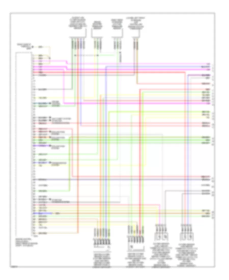
5.2L, Engine Performance Wiring Diagram (1 of 8) for Audi S6 Quattro 2010
 https://portal-diagnostov.com/license.html
Automotive Electricians Portal FZCO
Automotive Electricians Portal FZCO
https://portal-diagnostov.com/license.html
https://portal-diagnostov.com/license.html
Automotive Electricians Portal FZCO
Automotive Electricians Portal FZCO
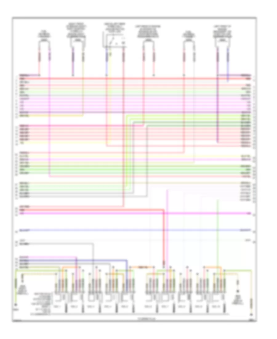
List of elements for 5.2L, Engine Performance Wiring Diagram (1 of 8) for Audi S6 Quattro 2010:
- (in right air filter housing) mass air flow (maf)/intake air temperature (iat) sensor
- (lower left front of engine) map controlled engine cooling thermostat
- (right rear of engine) low fuel pressure sensor
- (right side of firewall) g646
- Anti-theft system starting/ charging system
- Brake booster pressure sensor
- Cooling fans system
- Cruise control system
- Engine control module (ecm) (right rear of engine compt, in plenum)
- Heated oxygen sensor (ho2s) &
- Heated oxygen sensor (ho2s) 2 & oxygen sensor (o2s) heater 2 (heated oxygen sensor (ho2s) 2: in bank 2 exhaust)
- Nca
- Oxygen sensor (o2s) 2 behind three way catalytic converter (twc) & oxygen sensor (o2s) heater 2 behind three way catalytic converter (twc) (oxygen sensor (o2s) 2: in bank 2 exhaust)
- Oxygen sensor (o2s) behind three way catalytic converter (twc) & oxygen sensor (o2s) heater 1 behind three way catalytic converter (twc) (oxygen sensor (o2s): in bank 1 exhaust)
- Oxygen sensor (o2s) heater (heated oxygen sensor (ho2s): in bank 1 exhaust)
- Red
- Starting/ charging system
- T94a
- Transmissions system
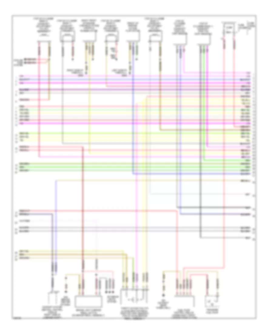
5.2L, Engine Performance Wiring Diagram (2 of 8) for Audi S6 Quattro 2010
 https://portal-diagnostov.com/license.html
Automotive Electricians Portal FZCO
Automotive Electricians Portal FZCO
https://portal-diagnostov.com/license.html
https://portal-diagnostov.com/license.html
Automotive Electricians Portal FZCO
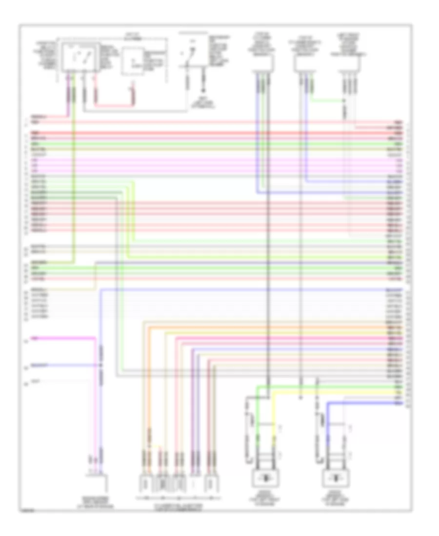
Automotive Electricians Portal FZCOList of elements for 5.2L, Engine Performance Wiring Diagram (2 of 8) for Audi S6 Quattro 2010:
- (front of engine) intake flap motor
- (left side of firewall) g645
- (right front of engine) variable intake manifold runner motor
- (right side of firewall) g646
- (top of cylinder bank 1) camshaft adjustment valve 1
- (top of cylinder bank 1) camshaft adjustment valve 1 (exhaust)
- (top of cylinder bank 1) camshaft position (cmp) sensor
- (top of cylinder bank 1) camshaft position (cmp) sensor 3
- (top of cylinder bank 2) camshaft adjustment valve 2
- (top of cylinder bank 2) camshaft adjustment valve 2 (exhaust)
- Brake light & brake pedal switch (on brake pedal assembly)
- Comfort system central control module (right side of luggage compt)
- Cooling fans system
- Exterior lights system
- Fuel pump control module (under right front luggage compt floor)
- Fuse 30a
- Fuse holder
- Fuse panel sc
- G45 (behind center of dash)
- G51 (on right rear wheelwell)
- Red
- T10y
- Throttle position (tp) & accelerator pedal position (app) sensor 2 (top of accelerator pedal assembly)
- Transfer fuel pump
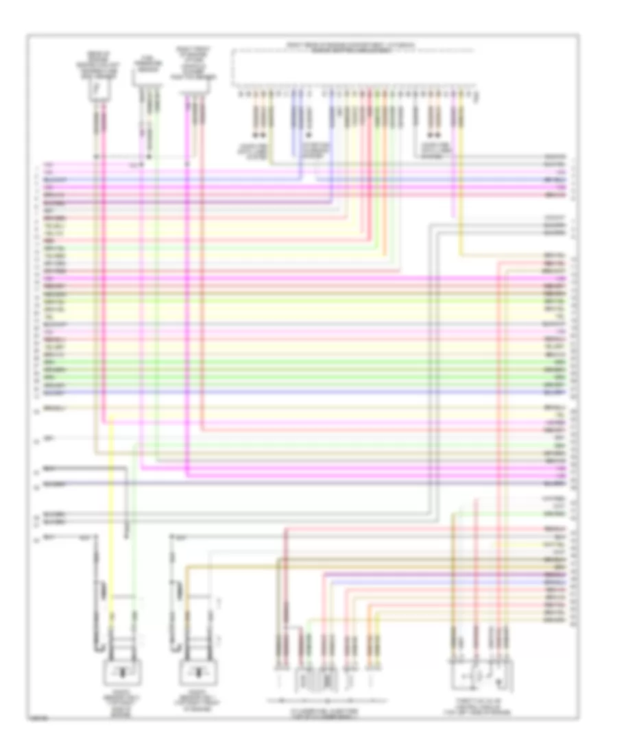
5.2L, Engine Performance Wiring Diagram (3 of 8) for Audi S6 Quattro 2010
 https://portal-diagnostov.com/license.html
Automotive Electricians Portal FZCO
Automotive Electricians Portal FZCO
https://portal-diagnostov.com/license.html
https://portal-diagnostov.com/license.html
Automotive Electricians Portal FZCO
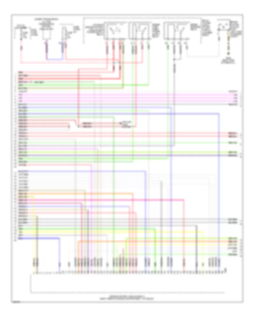
Automotive Electricians Portal FZCOList of elements for 5.2L, Engine Performance Wiring Diagram (3 of 8) for Audi S6 Quattro 2010:
- (rear of engine) engine coolant temperature (ect) sensor
- (right front of engine) intake manifold runner position sensor
- (right rear of engine compartment, in plenum) engine control module (ecm)
- Computer data lines system
- Cylinder fuel injectors (top of cylinder bank 1)
- Fuel pressure sensor
- Knock sensor (ks) 1 (top right front of engine)
- Knock sensor (ks) 2 (top right side of engine)
- Nca
- Red
- Starting/ charging system
- T94a
- Throttle valve control module (top left side of engine)
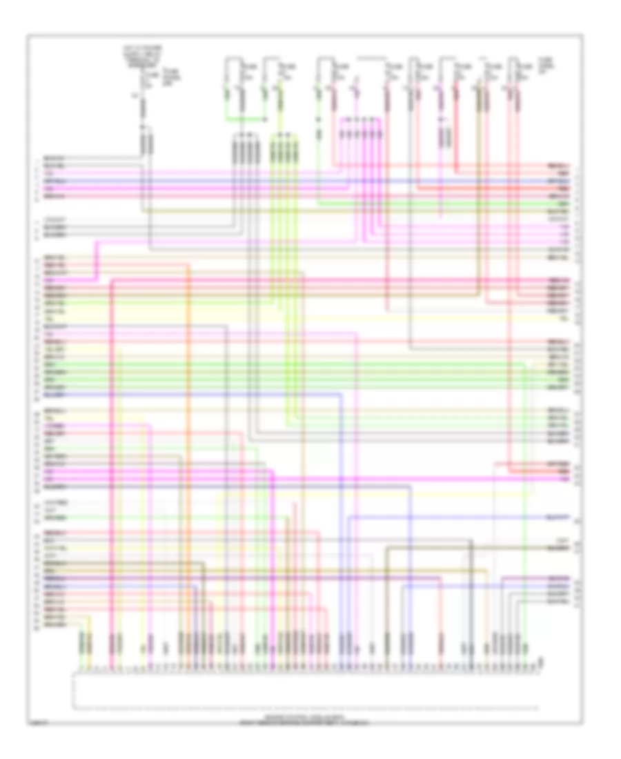
5.2L, Engine Performance Wiring Diagram (4 of 8) for Audi S6 Quattro 2010
 https://portal-diagnostov.com/license.html
Automotive Electricians Portal FZCO
Automotive Electricians Portal FZCO
https://portal-diagnostov.com/license.html
https://portal-diagnostov.com/license.html
Automotive Electricians Portal FZCO
Automotive Electricians Portal FZCOList of elements for 5.2L, Engine Performance Wiring Diagram (4 of 8) for Audi S6 Quattro 2010:
- 2a red
- Engine control module (ecm) (right rear of engine compartment, in plenum)
- Fuse 10a
- Fuse 15a
- Fuse 30a
- Fuse 5a
- Fuse panel sa
- Fuse panel sb
- Red
- T60a
5.2L, Engine Performance Wiring Diagram (5 of 8) for Audi S6 Quattro 2010
 https://portal-diagnostov.com/license.html
Automotive Electricians Portal FZCO
Automotive Electricians Portal FZCO
https://portal-diagnostov.com/license.html
https://portal-diagnostov.com/license.html
Automotive Electricians Portal FZCO
Automotive Electricians Portal FZCOList of elements for 5.2L, Engine Performance Wiring Diagram (5 of 8) for Audi S6 Quattro 2010:
- (above left rear wheelwell) leak detection pump (ldp)
- (left front of engine) secondary air injection (air) solenoid valve
- (left rear of engine) evaporative emission (evap) canister purge regulator valve
- (right front of engine compt) right electro- hydraulic engine mount solenoid valve
- Coil 1
- Coil 10
- Coil 2
- Coil 3
- Coil 4
- Coil 5
- Coil 6
- Coil 7
- Coil 8
- Coil 9
- Fuel metering valve
- Fuel metering valve 2
- G600
- G601
- G645 (left side of firewall)
- G646 (right side of firewall)
- Ignition coils w/ power output stage (1, 2, 3, 4 & 5: top of cylinder bank 1) (6, 7, 8, 9 & 10: top of cylinder bank 2)
- Nca
- Red
- To spark plug
5.2L, Engine Performance Wiring Diagram (6 of 8) for Audi S6 Quattro 2010
 https://portal-diagnostov.com/license.html
Automotive Electricians Portal FZCO
Automotive Electricians Portal FZCO
https://portal-diagnostov.com/license.html
https://portal-diagnostov.com/license.html
Automotive Electricians Portal FZCO
Automotive Electricians Portal FZCOList of elements for 5.2L, Engine Performance Wiring Diagram (6 of 8) for Audi S6 Quattro 2010:
- (left front of engine) intake manifold runner position sensor 2
- (top of cylinder bank 2) camshaft position (cmp) sensor 2
- (top of cylinder bank 2) camshaft position (cmp) sensor 4
- 4-position relay & fuse panel (in right plenum chamber e-box)
- 50a
- Cylinder fuel injectors (top of cylinder bank 2)
- Engine speed (rpm) sensor (at rear of engine)
- G647 (left side of firewall)
- Hot at all times
- Knock sensor 3 (top left front of engine)
- Knock sensor 4 (top left side of engine)
- Nca
- Red
- Secon- dary air injection (air) pump relay
- Secondary air injection (air) pump fuse
- Secondary air injection (air) pump motor (below left long- member)
5.2L, Engine Performance Wiring Diagram (7 of 8) for Audi S6 Quattro 2010
 https://portal-diagnostov.com/license.html
Automotive Electricians Portal FZCO
Automotive Electricians Portal FZCO
https://portal-diagnostov.com/license.html
https://portal-diagnostov.com/license.html
Automotive Electricians Portal FZCO
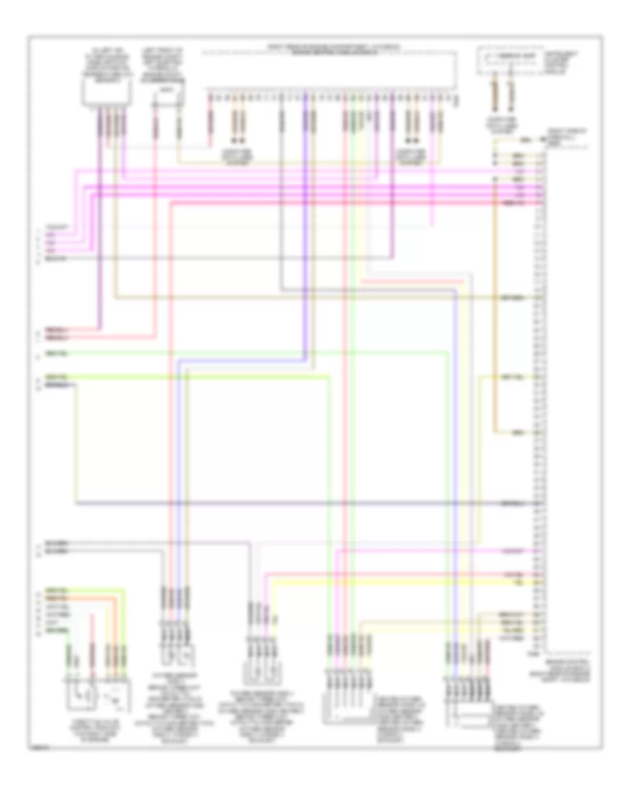
Automotive Electricians Portal FZCOList of elements for 5.2L, Engine Performance Wiring Diagram (7 of 8) for Audi S6 Quattro 2010:
- (under transmission oil pan) transmission control module(tcm)
- Brake booster relay
- Brake system vacuum pump (left side of engine compt)
- Cooling fans system
- Engine control module (ecm) 2 (right rear of engine compartment, in plenum)
- Fuse 10a
- Fuse 110a
- Fuse panel sa
- G646 (right side of firewall)
- Hot at all times
- Main fuse panel
- Red
- Relay holder (e-box) (in left plenum chamber e-box)
- T60b
5.2L, Engine Performance Wiring Diagram (8 of 8) for Audi S6 Quattro 2010
 https://portal-diagnostov.com/license.html
Automotive Electricians Portal FZCO
Automotive Electricians Portal FZCO
https://portal-diagnostov.com/license.html
https://portal-diagnostov.com/license.html
Automotive Electricians Portal FZCO
Automotive Electricians Portal FZCOList of elements for 5.2L, Engine Performance Wiring Diagram (8 of 8) for Audi S6 Quattro 2010:
- (in left air filter housing) mass air flow (maf)/intake air temperature (iat) sensor 2
- (left front of engine compt) left electro- hydraulic engine mount solenoid valve
- (right rear of engine compartment, in plenum) engine control module (ecm) 2
- (right side of firewall) g646
- Computer data lines system
- Display unit
- Engine control module (ecm) 2 (right rear of engine compt, in plenum)
- Heated oxygen sensor (h02s) 3 & oxygen sensor (o2s) heater 3 (heated oxygen sensor (h02s) 3: in bank 3 exhaust)
- Heated oxygen sensor (ho2s) 4 & oxygen sensor (o2s) heater 4 (heated oxygen sensor (h02s) 4: in bank 4 exhaust)
- Instrument cluster control module
- Nca
- Oxygen sensor (o2s) 3 behind three way catalytic converter (twc) & oxygen sensor (o2s) heater 3 behind three way catalytic converter (twc) (oxygen sensor (o2s) 3: in bank 3 exhaust)
- Oxygen sensor (o2s) 4 behind three way catalytic converter (twc) & oxygen sensor (o2s) heater 4 behind three way catalytic converter (oxygen sensor (o2s) 4: in bank 4 exhaust)
- T94b
- Throttle valve control module 2 (top right side of engine)

 Čeština
 Dansk
Dansk Deutsch
 Ελληνικά
 English
 English
 Español
 Suomi
Suomi Français
 Français
 עברית
עברית Hrvatski
 Magyar
 Italiano
 한국어
한국어 Nederlands
 Polski
 Português
 Português
 Română
 Русский
 Slovenčina
 Slovenščina
 Svenska
 Türkçe
 中文 (中国)
