ENGINE PERFORMANCE
IMA Wiring Diagram (1 of 5) for Honda Insight 2003
 https://portal-diagnostov.com/license.html
Automotive Electricians Portal FZCO
Automotive Electricians Portal FZCO
https://portal-diagnostov.com/license.html
https://portal-diagnostov.com/license.html
Automotive Electricians Portal FZCO
Automotive Electricians Portal FZCO
List of elements for IMA Wiring Diagram (1 of 5) for Honda Insight 2003:
- (behind seat, middle g502 of floor)
- (left side of intelligent power unit compt)
- A10
- A11
- A12
- A13
- A14
- A15
- A16
- A17
- A18
- A19
- A20
- A21
- A22
- A23
- A24
- A25
- A26
- A27
- A28
- A29
- A30
- A31
- A32
- Abs system
- Absbusy
- B10
- B11
- B12
- B13
- B14
- B15
- B16
- B17
- B18
- B19
- B20
- B21
- B22
- B23
- B24
- B25
- Cnt
- Dvinh
- Fot
- Fsc
- Fuse 7.5a
- Fuse 80a
- G101 (middle of engine)
- G502 (behind seat, middle of floor)
- Gun
- Gup
- Gvn
- Gvp
- Gwn
- Gwp
- High voltage contactor relay
- Hot at all times
- Ig1
- Iga1
- Iga2
- Ighld
- Ignition hold relay
- Ima diode (middle front of roof)
- Ipin
- Iuph
- Ivph
- Iwph
- J/c c507
- J/c c508
- Lg1
- Lg2
- Mamode2
- Mcm (right side of intelligent power unit compt)
- Motfsa
- Motfsb
- Motor stator
- Motstb
- Mpi module (in power control unit)
- Nca
- Pdufan
- Pdufanh
- Pg1
- Pg2
- Power control unit (left front side of intellegent power unit compt)
- Pre
- Scs
- Sg4
- Sg6
- Sg7
- Sg8
- Sg9
- Tdv
- Tha
- Thb
- U phase motor current sensor
- Under- dash fuse/ relay box
- Under- hood fuse/ relay box
- V phase motor current sensor
- Vbu
- Vdd
- Vgg
- Vgln
- Vglp
- Vgun
- Vgup
- Vgvn
- Vgvp
- Vgwn
- Vgwp
- Vpin
- W phase motor current sensor
- Warn
IMA Wiring Diagram (2 of 5) for Honda Insight 2003
 https://portal-diagnostov.com/license.html
Automotive Electricians Portal FZCO
Automotive Electricians Portal FZCO
https://portal-diagnostov.com/license.html
https://portal-diagnostov.com/license.html
Automotive Electricians Portal FZCO
Automotive Electricians Portal FZCOList of elements for IMA Wiring Diagram (2 of 5) for Honda Insight 2003:
- (behind seat, middle of floor) g502
- (left side of intelligent power unit compt)
- (left side of intelligent power unit compt) mpi module fan
- (middle of engine) g101
- 30a
- A red
- A10
- A11
- A12
- A13
- A14
- A15
- A16
- A17
- A18
- A19
- A20
- A21
- A22
- A23
- A24
- A25
- A26
- B red
- B10
- B11
- B12
- B13
- B14
- B15
- B16
- C red
- C10
- C11
- C12
- D red
- Dc-dc converter fuse
- Fot
- Fsc
- Fuse 15a
- G101
- G502 (behind seat, middle of floor)
- Gun
- Gup
- Gvn
- Gvp
- Gwn
- Gwp
- High speed mpi module fan control relay
- High speed mpi module fan control resistor
- Hot at all times
- Iga
- J/c c507
- J/c c508
- Low speed mpi module fan control relay
- Low speed mpi module fan control resistor
- Nca
- Red
- Sg10
- Sg9
- Tha
- Thb
- Under- hood fuse/ relay box
- Vdd
- Vgg
- Vgln
- Vglp
- Vgun
- Vgup
- Vgvn
- Vgvp
- Vgwn
- Vgwp
- Voltage converter module (in power control unit)
- Vpin
- Vref
IMA Wiring Diagram (3 of 5) for Honda Insight 2003
 https://portal-diagnostov.com/license.html
Automotive Electricians Portal FZCO
Automotive Electricians Portal FZCO
https://portal-diagnostov.com/license.html
https://portal-diagnostov.com/license.html
Automotive Electricians Portal FZCO
Automotive Electricians Portal FZCOList of elements for IMA Wiring Diagram (3 of 5) for Honda Insight 2003:
- (middle of engine) g101
- (not used)
- (on junction board) bypass contactor
- (right side of intelligent power unit compt)
- A21
- B19
- B20
- Battery current sensor (on junction block)
- Battery module fan motor
- Battery module fan resistor (on jucntion board)
- Bypass resistor
- C104
- Cpu
- Dc-dc converter (in power control unit)
- Fuse 7.5a
- G502 (behind seat, middle of floor)
- G651 (left rear side of floor)
- Gauge assembly
- Gnd
- High speed battery module fan control relay (on jucntion board)
- High voltage contactor (on junction board)
- Hot in on or start
- Ig1
- Ignition
- Ima syst
- Ima system ind
- Ims syst
- J/c c507
- J/c c508
- Low speed battery module fan control relay (on jucntion board)
- Mpi module current sensor (on junction block)
- Nca
- Not used
- Red
- Starting/ charging system
- Under- dash fuse/ relay box
- Voltage feed
- Vss (on left side of eng compt)
IMA Wiring Diagram (4 of 5) for Honda Insight 2003
 https://portal-diagnostov.com/license.html
Automotive Electricians Portal FZCO
Automotive Electricians Portal FZCO
https://portal-diagnostov.com/license.html
https://portal-diagnostov.com/license.html
Automotive Electricians Portal FZCO
Automotive Electricians Portal FZCOList of elements for IMA Wiring Diagram (4 of 5) for Honda Insight 2003:
- (middle of engine) g101
- 100a
- A19
- Acttrq
- B14
- Battery module
- Battery module switch (under small cover on intelligent power)
- Braided wires
- Capacitor assembly
- Cmdpwr
- D13
- D14
- D15
- Ecm (on right side of floor)
- Engtrq
- Eps control unit (under right side of dash)
- J/c c105
- Mamod1
- Mamod2
- Motfsa
- Motfsb
- Motor commutation sensor (on lower right rear of eng)
- Motstb
- Nca
- Nep
- Pnk
- Power control unit (pcu)
- Red
- Snubber unit
- Tcm
- Test tachometer connector (left side of eng compt)
- Y capacitor
IMA Wiring Diagram (5 of 5) for Honda Insight 2003
 https://portal-diagnostov.com/license.html
Automotive Electricians Portal FZCO
Automotive Electricians Portal FZCO
https://portal-diagnostov.com/license.html
https://portal-diagnostov.com/license.html
Automotive Electricians Portal FZCO
Automotive Electricians Portal FZCOList of elements for IMA Wiring Diagram (5 of 5) for Honda Insight 2003:
- (b1-b7 not used)
- (b13-b18 not used)
- (c1-c4 not used)
- (dlc) (behind center of dash)
- (e1-e3 & e5-e7 not used)
- (middle of
- A11
- A12
- A13
- A14
- A15
- A16
- A20
- A21
- A23 not used) a17,a18,a19,a22, (a5,a6,a9,a10,
- A24
- A25
- A26
- Acttrq
- B10
- B11
- B12
- B19
- B20
- B21
- B22
- Battery condition monitor (bcm) module (in middle of intelligent power unit compt)
- Battery module
- Battfanh
- Battfanl
- Battsci1
- Battsci2
- C10
- C11
- C12
- C13
- C14
- C15
- C16
- C17
- C18
- C19
- C20
- C21
- C22
- C23
- C24
- C25
- C26
- C27
- C28
- C29
- C30
- C31
- Cma
- Cmb
- Cmc
- Cmdpwr
- D10
- D11
- D12
- D13
- D14
- D15
- D16
- Data link connector
- Engtrg
- G101 g502 (behind seat, middle of floor) engine)
- Iga1
- Iga2
- Ipwr +
- Ipwr -
- Isoc
- J/c c507
- J/c c508
- Lg1
- Lg2
- Mamode1
- Mcm (right side of intelligent power unit compt)
- Metsci1
- Metsci2
- Nca
- Nep
- Pg1
- Pg2
- Pnk
- Ptc +
- Ptc -
- Qbatt
- Red
- Sg1
- Sg10
- Sg2
- Sg3
- Tbatt sg
- Tbatt1
- Tbatt2
- Tbatt3
- Tbatt4
- Tdx/rdx
- Vbu
- Vcc1
- Vcc2
- Vcc3
- Vcc4
- Vcc5
- Vcc6
- Vcc7
- Vhb+
- Vhb-
- Vhb0
- Vhb1
- Vhb10
- Vhb11
- Vhb2
- Vhb3
- Vhb4
- Vhb5
- Vhb6
- Vhb7
- Vhb8
- Vhb9
- Vref
- Vss
1.0L
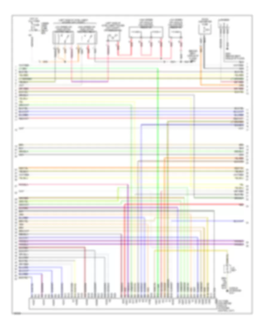
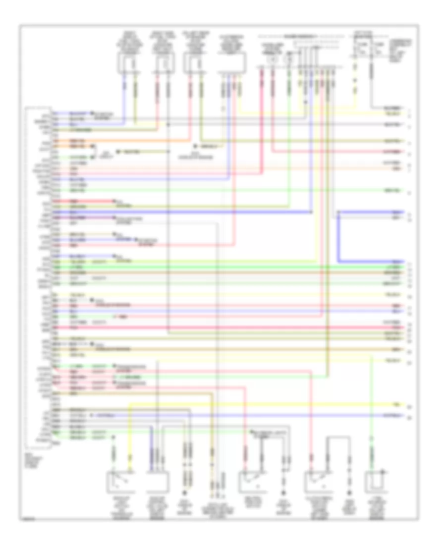
1.0L, Engine Controls Wiring Diagram (1 of 4) for Honda Insight 2003
 https://portal-diagnostov.com/license.html
Automotive Electricians Portal FZCO
Automotive Electricians Portal FZCO
https://portal-diagnostov.com/license.html
https://portal-diagnostov.com/license.html
Automotive Electricians Portal FZCO
Automotive Electricians Portal FZCOList of elements for 1.0L, Engine Controls Wiring Diagram (1 of 4) for Honda Insight 2003:
- (in steering column) immobilizer receiver unit
- (on left rear of engine) evap canister purge valve
- (right side of fuel tank) evap bypass solenoid valve
- (right side of fuel tank) evap canister vent shut valve
- (w/cvt)
- (w/m/t)
- 2wbs
- A/c system
- A10
- A11
- A12
- A13
- A14
- A15
- A16
- A17
- A18
- A19
- A20
- A21
- A22
- A23
- A24
- A25
- A26
- A27
- A28
- A29
- A30
- A31
- A32
- Acc
- Acs
- Atpd
- Atpnp
- Atpr
- B10
- B11
- B12
- B13
- B14
- B15
- B16
- B17
- B18
- B19
- B20
- B21
- B22
- B23
- B24
- B25
- Back-up light switch (on transaxle housing)
- Bksw
- Clsw
- Clutch pedal position switch (under left side of dash)
- Cooling fans system
- Cpu
- Data link connector (dlc) (behind center of dash)
- Dvc
- Dvct
- Ecm (on right side of floor)
- Egr
- Engrdy
- Exterior lights system
- Fanc
- Fuse 15a
- Fuse 7.5a
- G101 (middle of engine)
- G402 (left side of dash)
- Gauge assembly
- Hot in on or start
- Htrs
- Iacv
- Idle air control (iac) valve (on left side of engine)
- Idssw
- Igp1
- Igp2
- Ima circuit
- Immobilizer system indicator
- Imocd
- Imoen
- Imoflr
- Imolmp
- Inj1
- Inj2
- Inj3
- K-line
- Lg1
- Lg2
- M/p mon
- Mil
- Mtrtw
- Nep
- Neutral position switch
- Ntsw
- Pcs
- Pg1
- Pg2
- Pnk
- Po2htcr
- Ptank
- Red
- Rvssw
- Scs
- Slc
- Starting system
- Stc
- Sts
- Tim
- Transmissions system
- Underdash fuse/relay box (at left end of dash)
- Vbu
- Vref
- Vsv
- Vtec solenoid valve (on left side of engine)
- Vts
- Wen
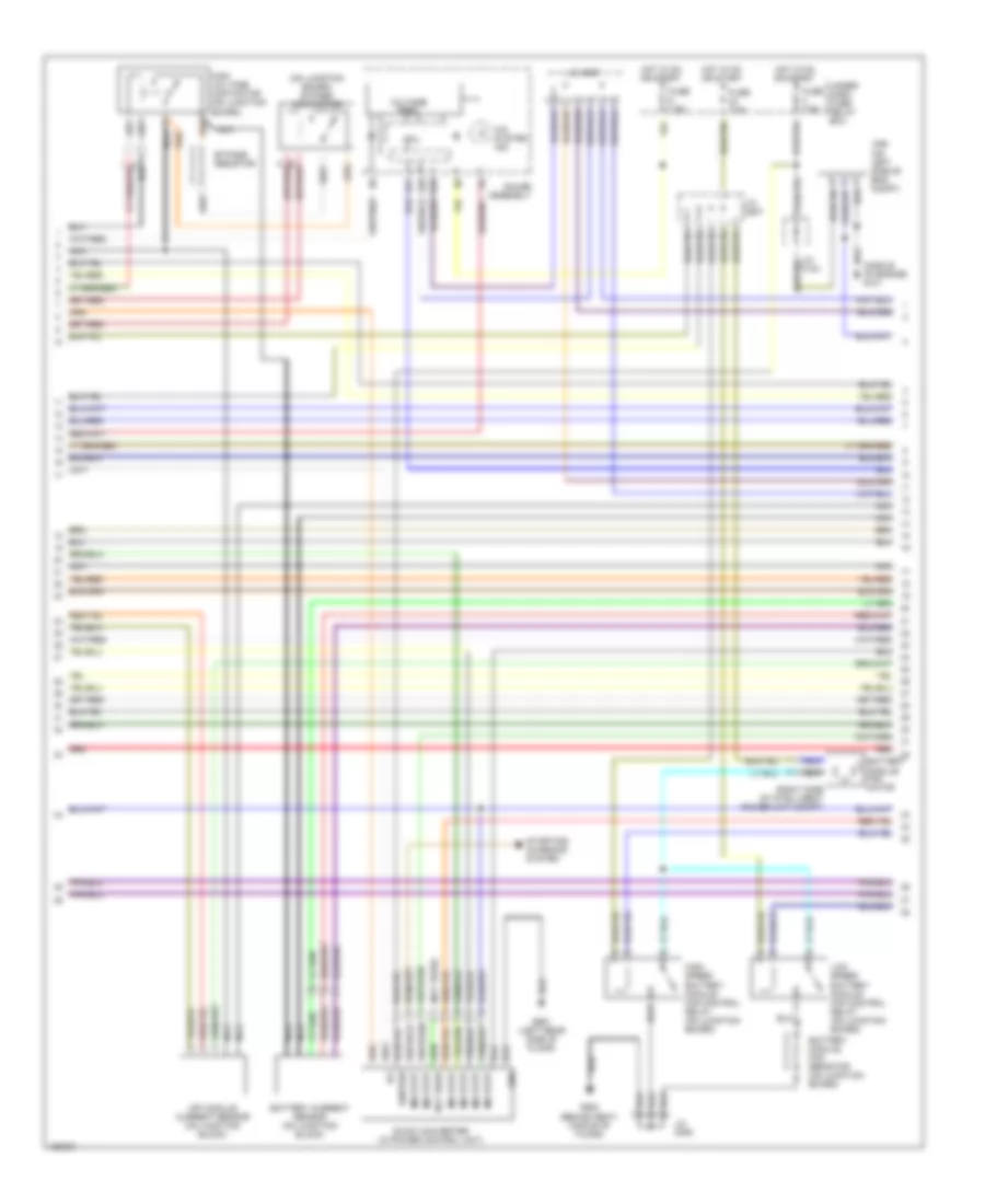
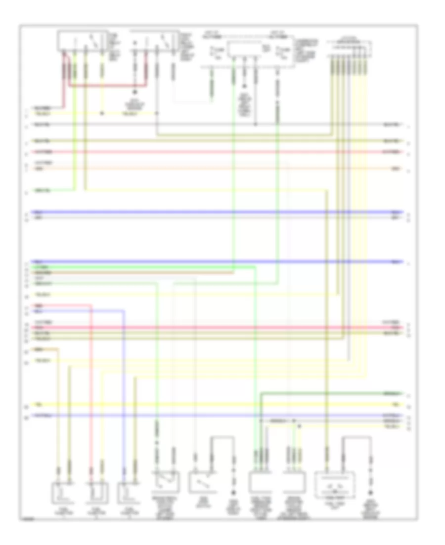
1.0L, Engine Controls Wiring Diagram (2 of 4) for Honda Insight 2003
 https://portal-diagnostov.com/license.html
Automotive Electricians Portal FZCO
Automotive Electricians Portal FZCO
https://portal-diagnostov.com/license.html
https://portal-diagnostov.com/license.html
Automotive Electricians Portal FZCO
Automotive Electricians Portal FZCOList of elements for 1.0L, Engine Controls Wiring Diagram (2 of 4) for Honda Insight 2003:
- A17
- Brake booster vacuum sensor (on left rear of engine compt)
- Brake pedal position switch (under left side of dash)
- Eld unit
- Fuel cut relay (in multi- relay box)
- Fuel injector
- Fuel pump
- Fuel tank pressure sensor (right side of fuel tank)
- Fuel tank unit
- Fuse 10a
- Fuse 15a
- G101 (middle of engine)
- G301 (above left front wheel- well)
- G402 (left side of dash)
- G502 (behind seat, middle of engine)
- Hot at all times
- Idle stop switch
- J/c c104 (or j/c c105)
- Pgm-fi main relay (under left side of dash)
- Pnk
- Red
- Underhood fuse/relay box (left side of engine compt)
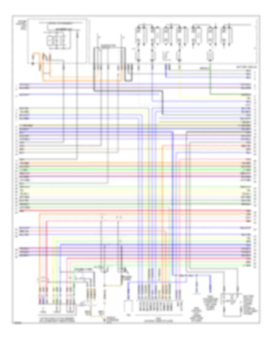
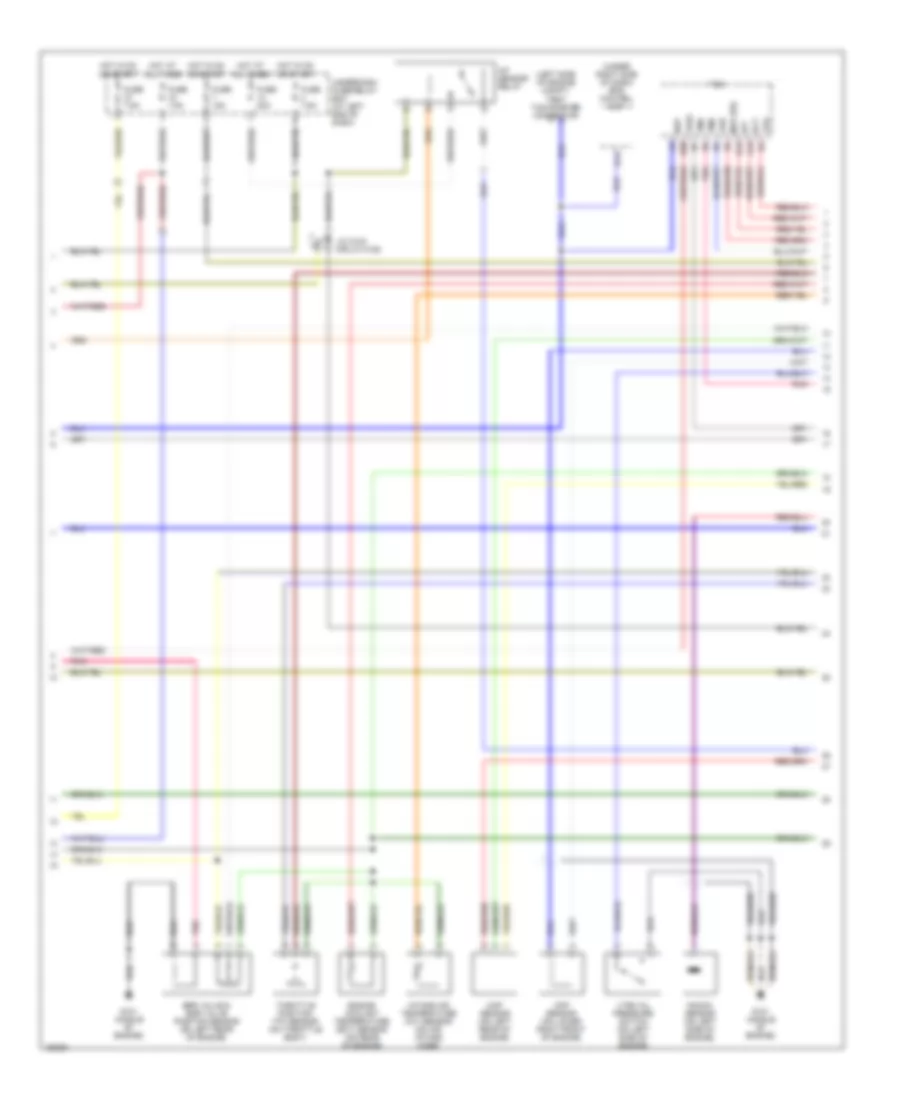
1.0L, Engine Controls Wiring Diagram (3 of 4) for Honda Insight 2003
 https://portal-diagnostov.com/license.html
Automotive Electricians Portal FZCO
Automotive Electricians Portal FZCO
https://portal-diagnostov.com/license.html
https://portal-diagnostov.com/license.html
Automotive Electricians Portal FZCO
Automotive Electricians Portal FZCOList of elements for 1.0L, Engine Controls Wiring Diagram (3 of 4) for Honda Insight 2003:
- (left side of engine compt) test tachometer connector
- (under right side of dash) eps control unit
- A/f sensor relay
- A19
- B14
- B19
- B20
- Braided
- Ckp sensor (on lower right front of engine)
- Ect
- Egr valve & egr valve position sensor (on left rear of engine)
- Engine coolant temperature (ect) sensor (on rear of engine)
- Fuse 15a
- Fuse 20a
- Fuse 7.5a
- G101 (middle of engine)
- Hot at all times
- Hot in on or start
- Iat
- Intake air temperature (iat) sensor (on air intake hose)
- J/c c105 (or j/c c108)
- Knock sensor (on left side of engine)
- Map (pb)
- Map sensor (on left rear of engine)
- Nep
- Pnk
- Tcm
- Throttle position (tp) sensor (on throttle body)
- Tma
- Tmb
- Tps
- Underdash fuse/relay box (at left end of dash)
- Vref
- Vss
- Vtec oil pressure switch (on left side of engine)
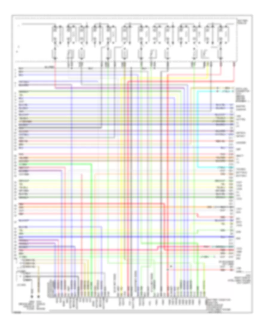
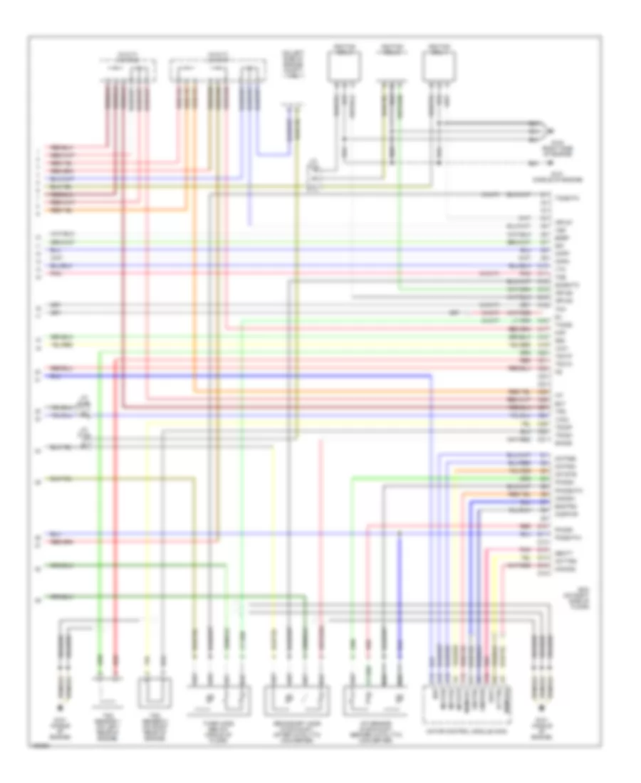
1.0L, Engine Controls Wiring Diagram (4 of 4) for Honda Insight 2003
 https://portal-diagnostov.com/license.html
Automotive Electricians Portal FZCO
Automotive Electricians Portal FZCO
https://portal-diagnostov.com/license.html
https://portal-diagnostov.com/license.html
Automotive Electricians Portal FZCO
Automotive Electricians Portal FZCOList of elements for 1.0L, Engine Controls Wiring Diagram (4 of 4) for Honda Insight 2003:
- (on left side of engine compt) vss
- (w/cvt)
- (w/cvt) j/c c107
- (w/cvt) j/c c108
- (w/m/t)
- A/f sensor (in exhaust, before catalytic converter)
- A15
- A16
- Acttrq
- Braided
- C10
- C11
- C12
- C13
- C14
- C15
- C16
- C17
- C18
- C19
- C20
- C21
- C22
- C23
- C24
- C25
- C26
- C27
- C28
- C29
- C30
- C31
- Ckpm
- Ckpp
- Cmdpwr
- D10
- D11
- D12
- D13
- D14
- D15
- D16
- Ecm (on right side of floor)
- Ect
- Egrp
- Engtrq
- G101 (middle of engine)
- G102 (right side of engine)
- Iat
- Ignition coil 1
- Ignition coil 2
- Ignition coil 3
- Igpls1
- Igpls2
- Igpls3
- J/c c104
- J/c c105
- Mamod1
- Mamod2
- Mamode1
- Mamode2
- Map
- Motfsa
- Motfsb
- Motor control module (mcm)
- Motstb
- Nep
- Pho2s+
- Pho2s-
- Pho2shtc
- Pnk
- Po2shtc+
- Qbat
- Qbatt
- Red
- Secondary ho2s (in exhaust, after catalytic converter)
- Sg1
- Sg2
- Sho2s
- Sil
- So2shtc
- Tdc sensor 1 (on left rear of engine)
- Tdc sensor 2 (on right rear of engine)
- Tdc1m
- Tdc1p
- Tdc2m
- Tdc2p
- Third ho2s (below middle of floor)
- Tho2s
- Tma
- Tmb
- To2shtc
- Tps
- Vcc1
- Vcc2
- Vss
- Vtm

 Čeština
 Dansk
Dansk Deutsch
 Ελληνικά
 English
 English
 Español
 Suomi
Suomi Français
 Français
 עברית
עברית Hrvatski
 Magyar
 Italiano
 한국어
한국어 Nederlands
 Polski
 Português
 Português
 Română
 Русский
 Slovenčina
 Slovenščina
 Svenska
 Türkçe
 中文 (中国)
