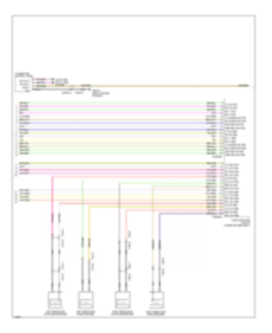
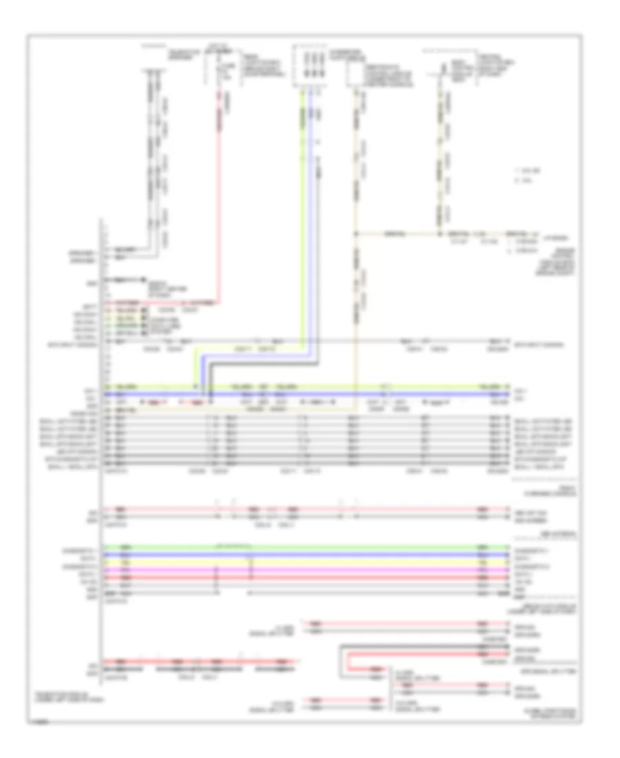
NAVIGATION
Blind Spot Monitoring Wiring Diagram for Land Rover Range Rover Sport Supercharged 2014
 https://portal-diagnostov.com/license.html
Automotive Electricians Portal FZCO
Automotive Electricians Portal FZCO
https://portal-diagnostov.com/license.html
https://portal-diagnostov.com/license.html
Automotive Electricians Portal FZCO
Automotive Electricians Portal FZCO
List of elements for Blind Spot Monitoring Wiring Diagram for Land Rover Range Rover Sport Supercharged 2014:
- C3a-a1
- C3a-a2
- C3b-a1
- C3b-a2
- C4br02a
- Capw02a
- Capw02b gnd mirror
- Cbpw04a
- Cbpw04b gnd passenger's door module
- Computer data lines system
- Driver side door mirror
- Driver's door module
- Fuse 10a
- G2d233 (left kick panel)
- G2d238 (right kick panel)
- G4d350 (left rear of luggage compt)
- Gnd
- Hot w/ extended ignition relay energized
- Left blind spot monitoring module (behind left end of rear bumper)
- Mirr gnd
- Mirror
- Ms can h
- Ms can l
- Passenger side door mirror
- Private can h
- Private can l
- Rear junction box (behind right quarterpanel)
- Right blind spot monitoring module (behind right end of rear bumper)
- Status led
- System
- System status
- System status led
- Vbatt
- Warning alert
- Warning alert led
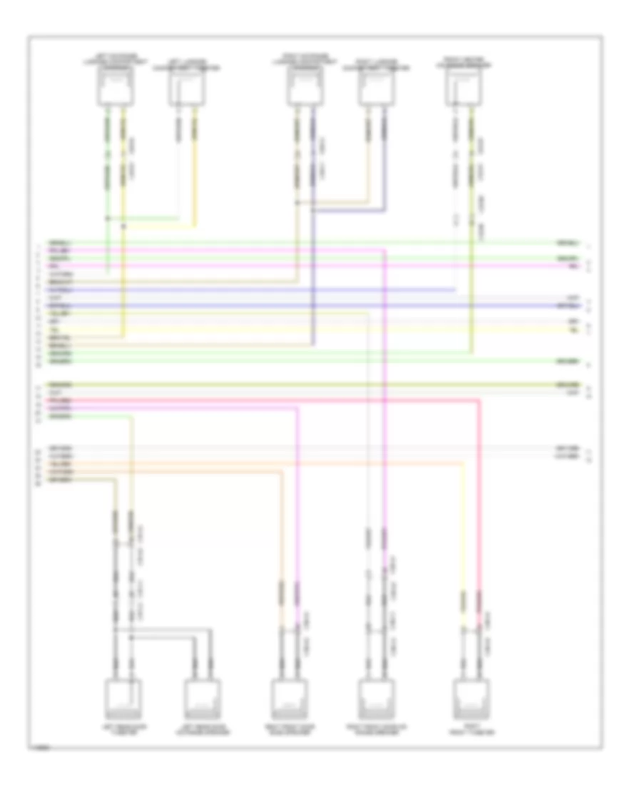
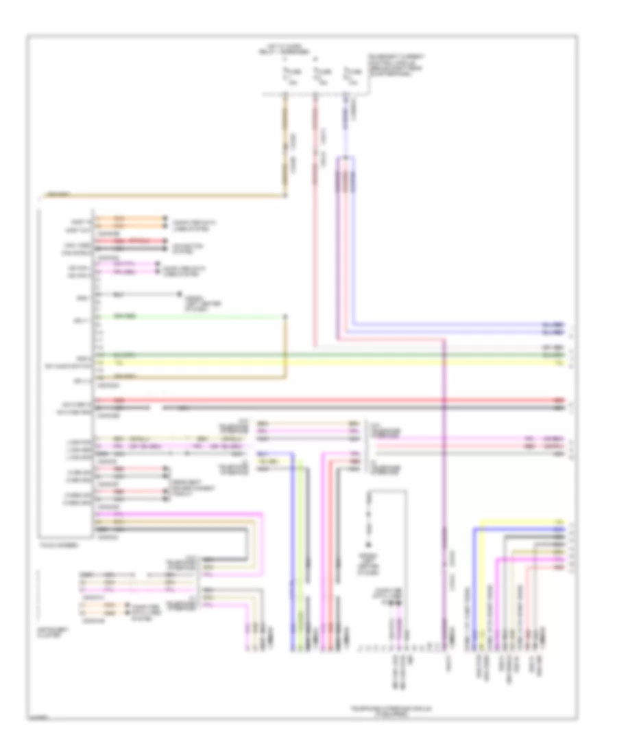
Multi Camera Wiring Diagram for Land Rover Range Rover Sport Supercharged 2014
 https://portal-diagnostov.com/license.html
Automotive Electricians Portal FZCO
Automotive Electricians Portal FZCO
https://portal-diagnostov.com/license.html
https://portal-diagnostov.com/license.html
Automotive Electricians Portal FZCO
Automotive Electricians Portal FZCOList of elements for Multi Camera Wiring Diagram for Land Rover Range Rover Sport Supercharged 2014:
- (right center of tailgate)
- 7-seat
- C11-d1
- C11-d2
- C11-e1
- C11-e2
- C2mc02a
- C2mc02c
- C31-g1
- C31-g2
- C31-h1
- C31-h2
- C32-h2 c32-h1
- C3a-am1
- C3a-am2
- C3b-am1
- C3b-am2
- C3mp22a
- C3mp22b
- C3mp22c
- C3mp22d
- C3mp22e
- C3mp22f
- C3mp22g
- C43-c1
- C43-c2
- C44-q1
- C44-q2
- C4br02a
- Camera shield
- Camera video
- Computer data lines system
- Fuse 10a
- G2d284 (left center of dash)
- G4d347 (left "c" pillar)
- Gnd
- Gnd 1
- Hot w/ extended ignition relay energized
- Image processing module (left "c" pillar)
- Left front proximity camera (behind left end of front bumper)
- Left mirror proximity camera (left front outside rearview mirror assembly)
- Lh front lin
- Lh front lvds pos
- Lh front lvds scr
- Lh front v pos
- Lh mirror lin
- Lh mirror lvds pos
- Lh mirror lvds scr
- Lh mirror v pos
- Lin
- Lvds +
- Lvds -
- Lvds pos
- Lvds scr gnd
- Ms can h
- Ms can l
- Nca
- Power
- Rear junction box (behind right quarterpanel)
- Rear lin
- Rear lvds pos
- Rear lvds scr
- Rear v pos
- Rearview camera
- Rh front lin
- Rh front lvds pos
- Rh front lvds scr
- Rh front v pos
- Rh mirror lin
- Rh mirror lvds scr
- Rh mirror v pos
- Right front proximity camera (behind right end of front bumper)
- Right mirror proximity camera (right front outside rearview mirror assembly)
- Scr
- Touch screen
- V pos
- Video +
- Video -
- W/ swc
- W/o swc
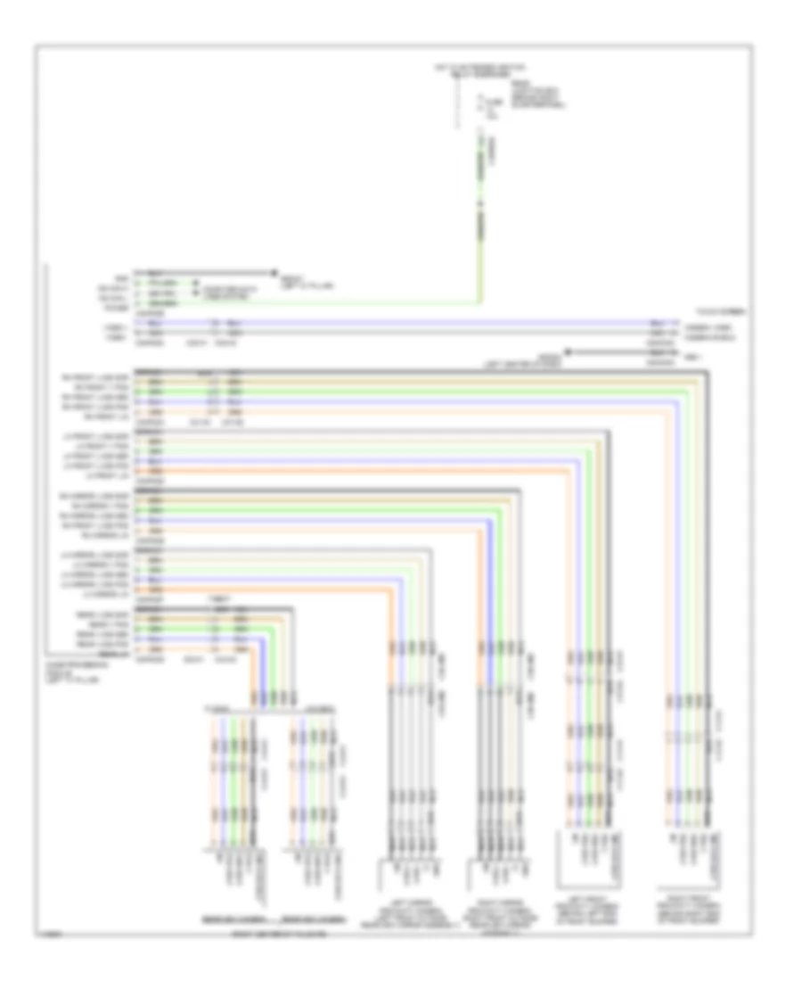
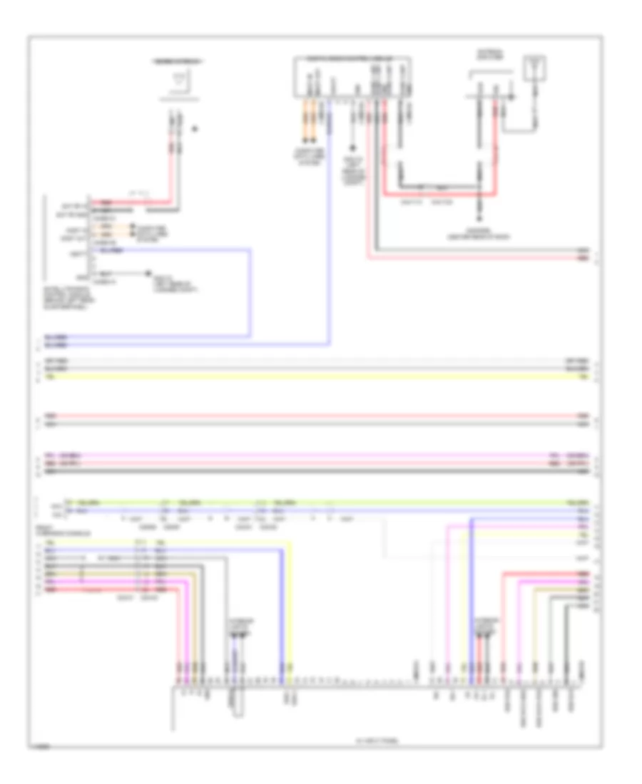
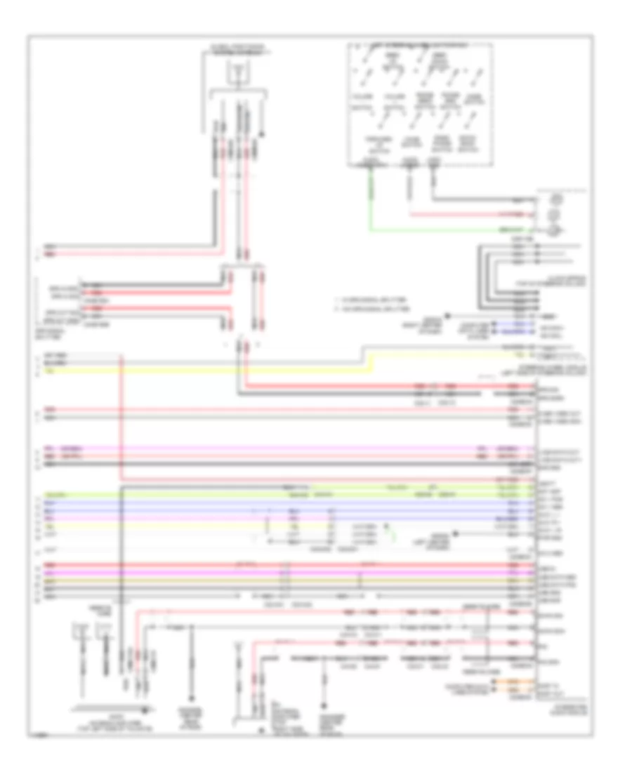
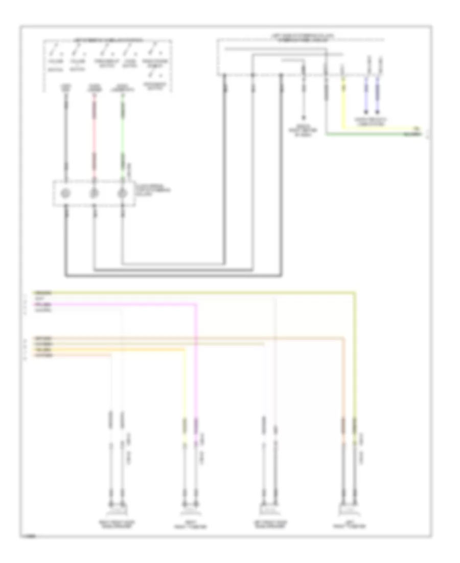
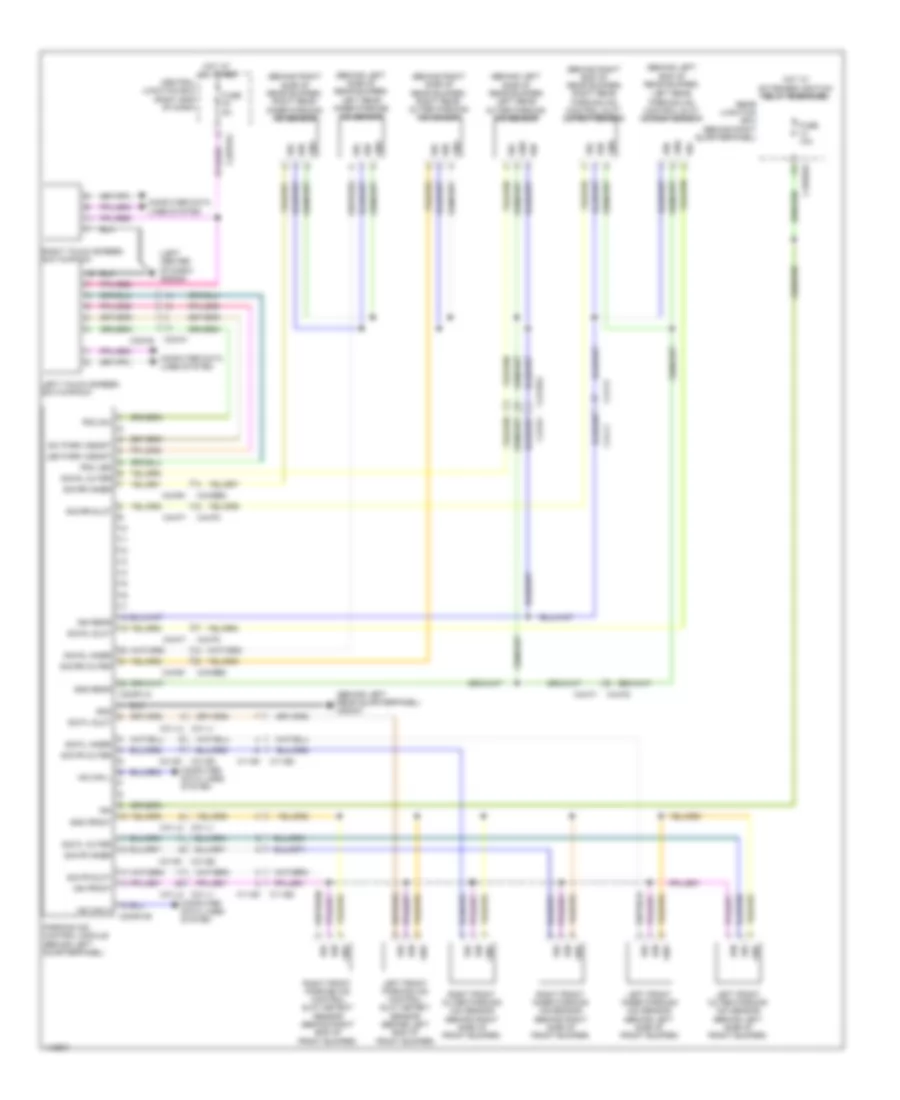
Navigation Wiring Diagram, 19-Speaker System (1 of 6) for Land Rover Range Rover Sport Supercharged 2014
 https://portal-diagnostov.com/license.html
Automotive Electricians Portal FZCO
Automotive Electricians Portal FZCO
https://portal-diagnostov.com/license.html
https://portal-diagnostov.com/license.html
Automotive Electricians Portal FZCO
Automotive Electricians Portal FZCOList of elements for Navigation Wiring Diagram, 19-Speaker System (1 of 6) for Land Rover Range Rover Sport Supercharged 2014:
- (under driver's seat)
- Audio amplifier module
- C29-a1
- C29-a2
- C37-a1
- C37-a2
- C38-a1
- C38-a2
- C38-c1 c38-c2
- C3me22a
- C3me22b
- C3me22c
- C3me22d
- C3me22e
- C3me22h
- C4br01a
- C4br02a
- Computer data lines system
- Data 1
- Data 2
- Fr cntr high pos
- Fr cntr mid pos
- Fuse 10a
- Fusible link 40a
- G3d161 (under center console)
- Gnd
- Gnd shield
- Hot at all times
- Hot w/ micro relay 1 energized
- Left rear door bass speaker
- Lf high pos
- Lf low pos
- Lf mid pos
- Lh surr pos
- Lr low pos
- Lr mid pos
- Most in
- Most out
- Nca
- Power
- Pwr
- Quiescent current control module (behind right rear quarterpanel)
- Rbd
- Rbd gnd
- Rear junction box (behind right quarterpanel)
- Red
- Rf high pos
- Rf low pos
- Rf mid pos
- Right rear door bass speaker
- Right rear door mid range speaker
- Right rear door tweeter
- Rr low pos
- Rr mid pos
- Scr
- Shield
- Sw 1 pos
- Sw 2 pos
- Vbatt
- Wireless headphones
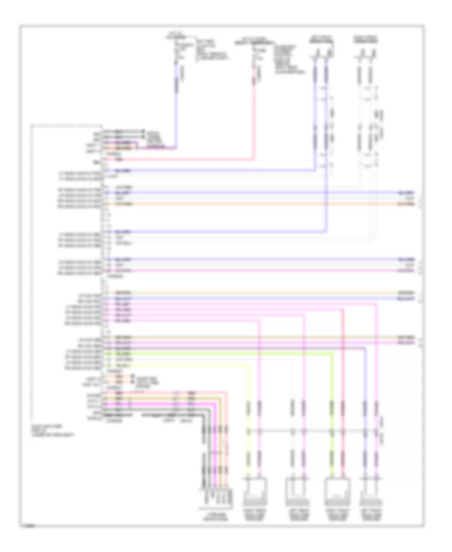
Navigation Wiring Diagram, 19-Speaker System (2 of 6) for Land Rover Range Rover Sport Supercharged 2014
 https://portal-diagnostov.com/license.html
Automotive Electricians Portal FZCO
Automotive Electricians Portal FZCO
https://portal-diagnostov.com/license.html
https://portal-diagnostov.com/license.html
Automotive Electricians Portal FZCO
Automotive Electricians Portal FZCOList of elements for Navigation Wiring Diagram, 19-Speaker System (2 of 6) for Land Rover Range Rover Sport Supercharged 2014:
- C22-d1
- C22-d2
- C32-n1
- C32-n2
- C37-a1 c37-a2
- C37-c1 c37-c2
- C3b-a1
- C3b-a2
- C3b-c1
- C3b-c2
- C49-c1
- C49-c2
- C49-d1
- C49-d2
- Front center mid range speaker
- Left luggage compartment tweeter
- Left mid range luggage compartment speaker
- Left rear door mid range speaker
- Left rear door tweeter
- Right front door bass speaker
- Right front door mid range speaker
- Right front tweeter
- Right luggage compartment tweeter
- Right mid range luggage compartment speaker
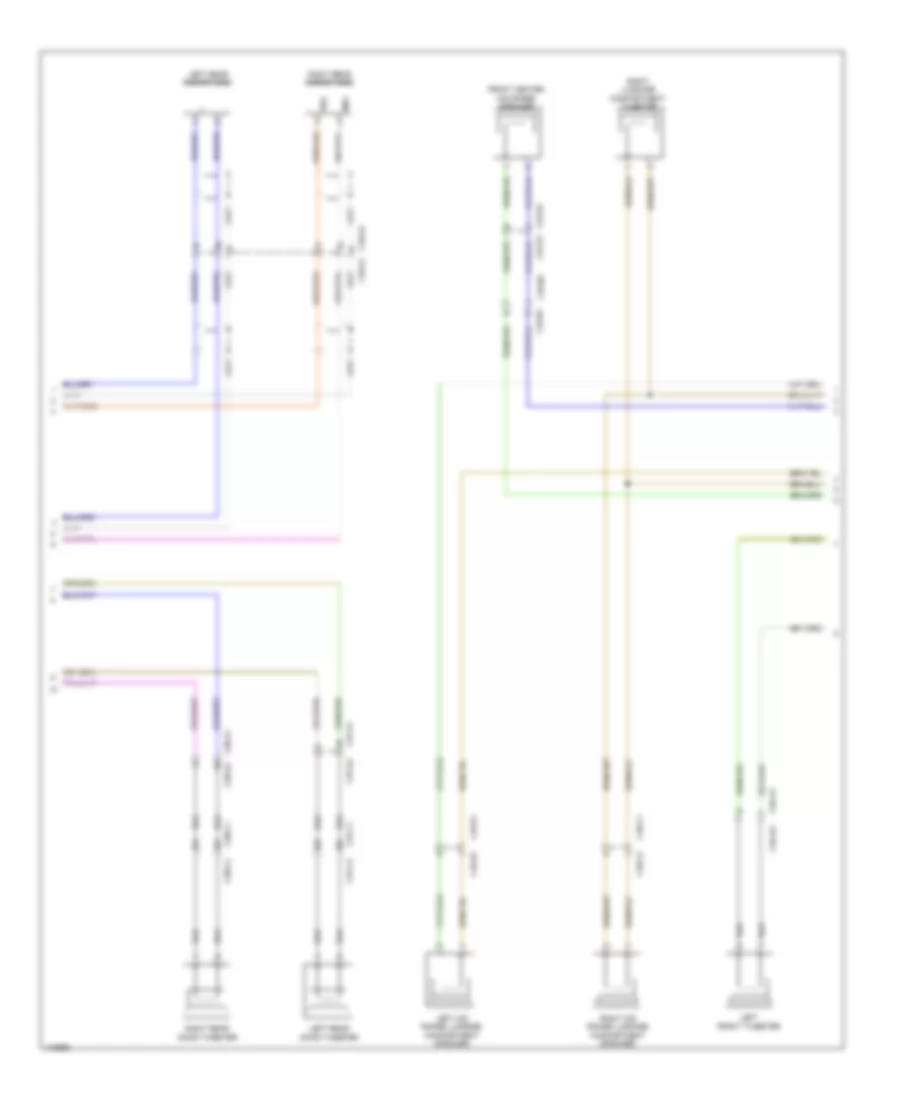
Navigation Wiring Diagram, 19-Speaker System (3 of 6) for Land Rover Range Rover Sport Supercharged 2014
 https://portal-diagnostov.com/license.html
Automotive Electricians Portal FZCO
Automotive Electricians Portal FZCO
https://portal-diagnostov.com/license.html
https://portal-diagnostov.com/license.html
Automotive Electricians Portal FZCO
Automotive Electricians Portal FZCOList of elements for Navigation Wiring Diagram, 19-Speaker System (3 of 6) for Land Rover Range Rover Sport Supercharged 2014:
- C22-d1
- C22-d2
- C2me14
- C2me14a
- C32-n1
- C32-n2
- C3a-a1
- C3a-a1 c3a-a2
- C3a-a2
- C3a-c1 c3a-c2
- Center front tweeter
- Computer data lines system
- G2d215 (right center of dash)
- Gnd
- Integrated control panel
- Left front door bass speaker
- Left front door mid range speaker
- Left front tweeter
- Ms can h
- Ms can l
- Subwoofer speaker
- Vbatt
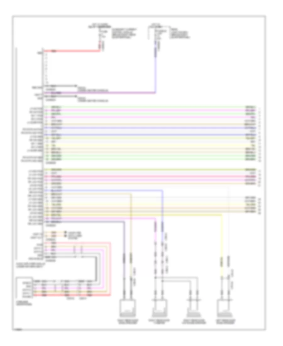
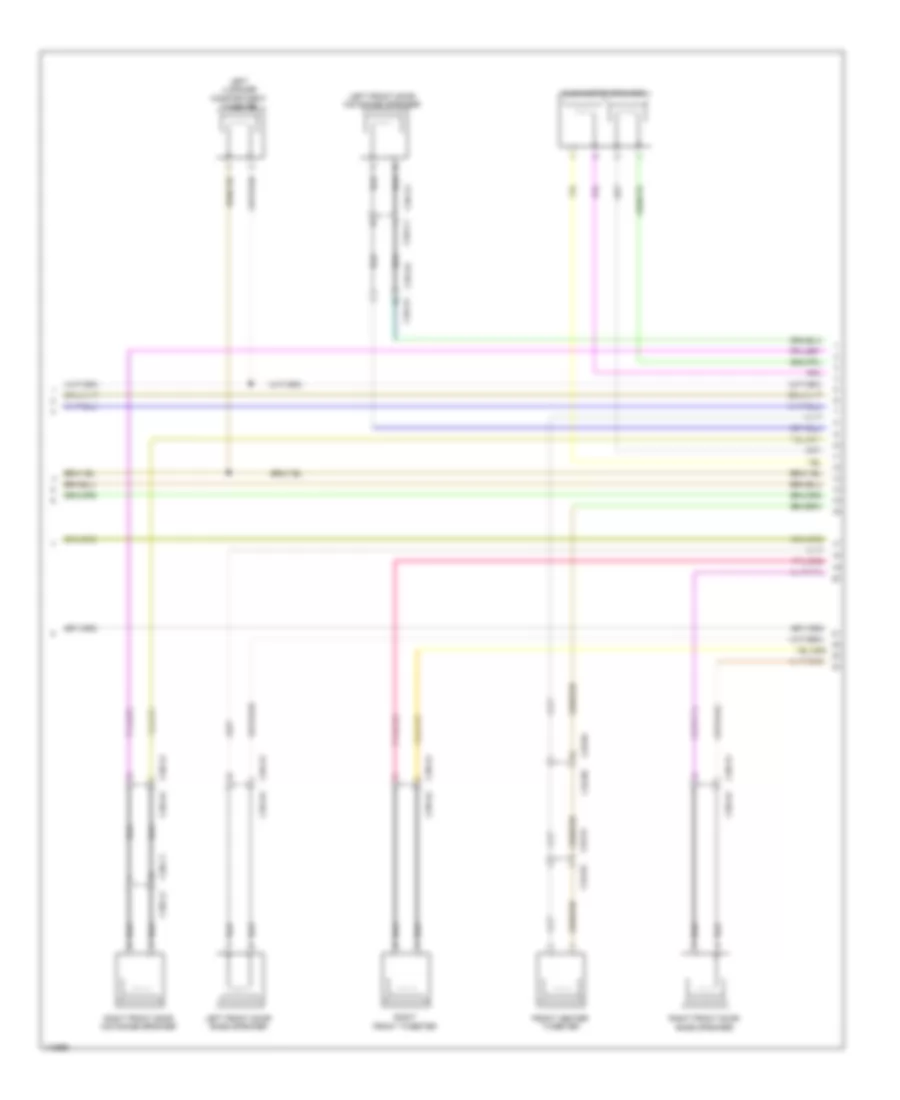
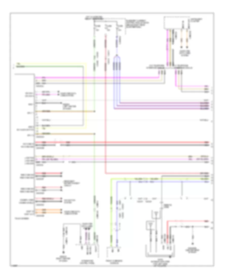
Navigation Wiring Diagram, 19-Speaker System (4 of 6) for Land Rover Range Rover Sport Supercharged 2014
 https://portal-diagnostov.com/license.html
Automotive Electricians Portal FZCO
Automotive Electricians Portal FZCO
https://portal-diagnostov.com/license.html
https://portal-diagnostov.com/license.html
Automotive Electricians Portal FZCO
Automotive Electricians Portal FZCOList of elements for Navigation Wiring Diagram, 19-Speaker System (4 of 6) for Land Rover Range Rover Sport Supercharged 2014:
- (pins: 1 to 13 not used)
- (pins: 16 to 20 not used)
- (pins: 24 to 28 not used)
- C23-a1
- C23-a2
- C2mc01b
- C2mc01c
- C2mc02a
- C2mc02b
- C2mc02c
- C2mc02d
- C2mc02e
- C2mc02f
- C2mc02i
- C2mc02j
- C2mm25a
- C2mm25b
- C2mm25d
- C2mm25e
- C2mm25f
- C32-f1
- C32-f2
- C32-n1
- C32-n2
- C4br01a
- Cam shield
- Cam video
- Computer data lines system
- Cvbs gnd
- Cvbs sig
- Cvbs2 gnd
- Cvbs2 sig
- Diag rtn
- Diag send
- Fuse 10a
- Fuse 15a
- G2d284 (left center of dash)
- Gnd
- Gnd 1
- Gnd 2
- Gnd shield
- Hot w/ micro relay 1 energized
- Iam cvbs gnd
- Iam cvbs in
- Instrument cluster
- Lvds pos
- Lvds scr
- Most in
- Most out
- Ms can h
- Ms can h (co)
- Ms can l
- Ms can l (co)
- Navigation system
- Nca
- Quiescent current control module (behind right rear quarterpanel)
- Rear seat entertainment circuit
- Red
- Scr
- Sply 1
- Sply 2
- Sw audio switch
- Telephone interface module (if equipped)
- Touch screen
- Usb d+
- Usb d-
- Usb gnd
- Usb v+
- Vbatt
- W/ telephone interface
- W/o telephone interface
Navigation Wiring Diagram, 19-Speaker System (5 of 6) for Land Rover Range Rover Sport Supercharged 2014
 https://portal-diagnostov.com/license.html
Automotive Electricians Portal FZCO
Automotive Electricians Portal FZCO
https://portal-diagnostov.com/license.html
https://portal-diagnostov.com/license.html
Automotive Electricians Portal FZCO
Automotive Electricians Portal FZCOList of elements for Navigation Wiring Diagram, 19-Speaker System (5 of 6) for Land Rover Range Rover Sport Supercharged 2014:
- Antenna amplifier
- Av input panel
- Band 3 ant gnd
- Band 3 ant gnd band l ant
- Band l ant
- C23-c1
- C23-c2
- C29-b1
- C29-b2
- C32-d1
- C32-d2
- C3me37a
- C3me37b
- C44-y1a
- C44-y2a
- C4me24a
- C4me24b
- C4me24c
- C4me41a
- C4me41b
- C4me41c
- Computer data lines system
- Diag +
- Diag -
- Digital radio control module
- Front overhead console
- G3d172 (left rear of luggage compt)
- G4d480bl (center rear of roof)
- Gnd
- Ill +
- Ill -
- Interior lights system
- Lh +
- Lh -
- Mic+
- Mic-
- Most in
- Most out
- Nca
- Red
- Rh +
- Rh -
- Sat rf gnd
- Sat rf in
- Satellite radio control module (behind left rear quarterpanel)
- Scn
- Sdars antenna
- Shield
- Sig
- Usb data pos
- Usb gnd
- Usb pos
- Usb scr
- Vbatt
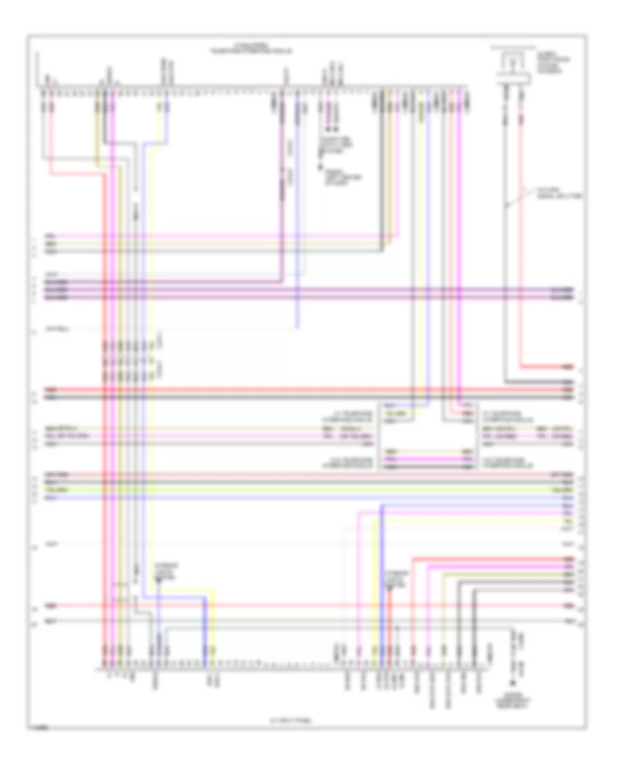
Navigation Wiring Diagram, 19-Speaker System (6 of 6) for Land Rover Range Rover Sport Supercharged 2014
 https://portal-diagnostov.com/license.html
Automotive Electricians Portal FZCO
Automotive Electricians Portal FZCO
https://portal-diagnostov.com/license.html
https://portal-diagnostov.com/license.html
Automotive Electricians Portal FZCO
Automotive Electricians Portal FZCOList of elements for Navigation Wiring Diagram, 19-Speaker System (6 of 6) for Land Rover Range Rover Sport Supercharged 2014:
- Am-fm scn
- Am-fm sig
- Am/fm antenna amplifier (top left side of tailgate)
- Ant amp
- Audio ladder
- Audio ladder rtn
- Aux1 l +
- Aux1 l r-
- Aux1 r +
- C23-a1
- C23-a2
- C2me03a
- C2me03d
- C2me03e
- C2me03f
- C2me03g
- C2me03h
- C2r115b
- C32-aa1
- C32-aa2
- C32-c1
- C32-c2
- C32-ga1
- C32-ga2
- C32-v1
- C32-v2
- C44-w1
- C44-w2
- C44-x1
- C44-x2
- C44-z1
- C44-z2
- C4me192a
- C4me192b
- C9me115
- C9me115a
- C9me46c
- C9mn03a
- Clock spring (top of steering column)
- Computer data lines system
- Cvbs video out
- Cvbs video scn
- Down/ back switch
- Ferrite core
- Fm antenna amplifier (top right side of tailgate)
- Fm2
- Fm2 scn c2me03c
- Forward/ up switch
- G2d216 (right center of dash)
- G2d284 (left center of dash)
- G4d480bl (center rear of roof)
- G4d480br (center rear of roof)
- Global positioning system antenna
- Gnd
- Gps in gnd
- Gps in sig
- Gps out gnd
- Gps out sig
- Gps scrn
- Gps sig
- Gps signal splitter
- Hs can h
- Hs can l
- Ice 1
- Ice 2
- Integrated audio module
- Left steering wheel switchpack
- Logic gnd
- Lvds data out+
- Lvds data out-
- Mic 1 pos
- Mode switch
- Most in
- Most out
- Nca
- Phone end switch
- Phone send switch
- Pwr
- Pwr gnd
- Radio phone switch
- Red
- Scn
- Scr
- Scr gnd
- Seek down switch
- Seek up switch
- Sig
- Steering wheel module (left side of steering column)
- Usb 5v
- Usb data pos
- Usb gnd
- Usb scr
- Vbatt
- Voice switch
- Volume + switch
- Volume - switch
- W/ gps signal splitter
- W/o gps signal splitter
Navigation Wiring Diagram, 23-Speaker System (1 of 7) for Land Rover Range Rover Sport Supercharged 2014
 https://portal-diagnostov.com/license.html
Automotive Electricians Portal FZCO
Automotive Electricians Portal FZCO
https://portal-diagnostov.com/license.html
https://portal-diagnostov.com/license.html
Automotive Electricians Portal FZCO
Automotive Electricians Portal FZCOList of elements for Navigation Wiring Diagram, 23-Speaker System (1 of 7) for Land Rover Range Rover Sport Supercharged 2014:
- Audio amplifier module (under driver's seat)
- Battery junction box (right rear of luggage compt)
- C29-a1
- C29-a2
- C29-b1
- C29-b2
- C3me22b
- C3me22c
- C3me22f
- C3me22g
- C3me22j
- C49-a1
- C49-a2
- C4bf01h
- C4br01a
- Computer
- Data 1
- Data 2
- Data lines
- Fuse 10a
- Fusible link 80a
- G3d161 (under center console)
- Gnd
- Hot at all times
- Hot w/ micro relay 1 energized
- Left front headliner speaker
- Left front microphone
- Left rear headliner speaker
- Lf headlining mic pos
- Lf headlining mic scr
- Lf headlining pos
- Lr headlining mic pos
- Lr headlining mic scr
- Lr headlining pos
- Lr high pos
- Most in
- Most out
- Nca
- Pos
- Power
- Quiescent current control module (behind right rear quarterpanel)
- Rbd
- Red
- Rf headlining mic pos
- Rf headlining mic scr
- Rf headlining pos
- Right front headliner speaker
- Right front microphone
- Right rear headliner speaker
- Rr headlining mic pos
- Rr headlining mic scr
- Rr headlining pos
- Rr high pos
- Scr
- Shield
- System
- Vbatt 1
- Vbatt 2
- Wireless headphones
Navigation Wiring Diagram, 23-Speaker System (2 of 7) for Land Rover Range Rover Sport Supercharged 2014
 https://portal-diagnostov.com/license.html
Automotive Electricians Portal FZCO
Automotive Electricians Portal FZCO
https://portal-diagnostov.com/license.html
https://portal-diagnostov.com/license.html
Automotive Electricians Portal FZCO
Automotive Electricians Portal FZCOList of elements for Navigation Wiring Diagram, 23-Speaker System (2 of 7) for Land Rover Range Rover Sport Supercharged 2014:
- C22-d2 c22-d1
- C32-n1
- C32-n2
- C37-a1
- C37-a2
- C37-c1
- C37-c2
- C38-a1
- C38-a2
- C38-c1
- C38-c2
- C3a-a1
- C3a-a2
- C49-a2 c49-a1
- C49-c1
- C49-c2
- C49-d1
- C49-d2
- Front center mid range speaker
- Left front tweeter
- Left mid range luggage compartment speaker
- Left rear door tweeter
- Left rear microphone
- Pos
- Right luggage compartment tweeter
- Right mid range luggage compartment speaker
- Right rear door tweeter
- Right rear microphone
Navigation Wiring Diagram, 23-Speaker System (3 of 7) for Land Rover Range Rover Sport Supercharged 2014
 https://portal-diagnostov.com/license.html
Automotive Electricians Portal FZCO
Automotive Electricians Portal FZCO
https://portal-diagnostov.com/license.html
https://portal-diagnostov.com/license.html
Automotive Electricians Portal FZCO
Automotive Electricians Portal FZCOList of elements for Navigation Wiring Diagram, 23-Speaker System (3 of 7) for Land Rover Range Rover Sport Supercharged 2014:
- C22-d1
- C22-d2
- C32-n1
- C32-n2
- C3a-a1
- C3a-a2
- C3a-c1
- C3a-c2
- C3b-a1
- C3b-a2
- C3b-c1
- C3b-c2
- Front center tweeter
- Left front door bass speaker
- Left front door mid range speaker
- Left luggage compartment tweeter
- Right front door bass speaker
- Right front door mid range speaker
- Right front tweeter
- Subwoofer speaker
Navigation Wiring Diagram, 23-Speaker System (4 of 7) for Land Rover Range Rover Sport Supercharged 2014
 https://portal-diagnostov.com/license.html
Automotive Electricians Portal FZCO
Automotive Electricians Portal FZCO
https://portal-diagnostov.com/license.html
https://portal-diagnostov.com/license.html
Automotive Electricians Portal FZCO
Automotive Electricians Portal FZCOList of elements for Navigation Wiring Diagram, 23-Speaker System (4 of 7) for Land Rover Range Rover Sport Supercharged 2014:
- Audio amplifier module (under driver's seat)
- C2me14
- C2me14a
- C37-a1
- C37-a2
- C37-c1
- C37-c2
- C38-a1
- C38-a2
- C38-c1
- C38-c2
- C3me22d
- C3me22e
- Centre high pos
- Centre mid pos
- Computer data lines system
- G2d215 (right center of dash)
- Gnd
- Integrated control panel
- Left rear door bass speaker
- Left rear door mid range speaker
- Lf high pos
- Lf low pos
- Lf mid pos
- Lh surround pos
- Lr low pos
- Lr mid pos
- Ms can h
- Ms can l
- Rf high pos
- Rf low pos
- Rf mid pos
- Rh surround pos
- Right rear door bass speaker
- Right rear door mid range speaker
- Rr low pos
- Rr mid pos
- Sw 1 pos
- Sw 2 pos
- Vbatt
Navigation Wiring Diagram, 23-Speaker System (5 of 7) for Land Rover Range Rover Sport Supercharged 2014
 https://portal-diagnostov.com/license.html
Automotive Electricians Portal FZCO
Automotive Electricians Portal FZCO
https://portal-diagnostov.com/license.html
https://portal-diagnostov.com/license.html
Automotive Electricians Portal FZCO
Automotive Electricians Portal FZCOList of elements for Navigation Wiring Diagram, 23-Speaker System (5 of 7) for Land Rover Range Rover Sport Supercharged 2014:
- (pins: 1 to 13 not used)
- (pins: 16 to 20 not used)
- (pins: 24 to 28 not used)
- C23-a1
- C23-a2
- C2mc01b
- C2mc01c
- C2mc02a
- C2mc02b
- C2mc02c
- C2mc02d
- C2mc02e
- C2mc02f
- C2mc02i
- C2mc02j
- C2mm25a
- C2mm25b
- C2mm25d
- C2mm25e
- C2mm25f
- C32-f1
- C32-f2
- C32-n1
- C32-n2
- C4br01a
- Cam shield
- Cam video
- Computer data lines system
- Cvbs gnd
- Cvbs sig
- Cvbs2 gnd
- Cvbs2 sig
- Diag rtn
- Diag send
- Fuse 10a
- Fuse 15a
- G2d284 (left center of dash)
- Gnd
- Gnd 1
- Gnd 2
- Gnd shield
- Hot w/ micro relay 1 energized
- Iam cvbs gnd
- Iam cvbs in
- Instrument cluster
- Lvds pos
- Lvds scr
- Most in
- Most out
- Ms can h
- Ms can h (co)
- Ms can l
- Ms can l (co)
- Navigation system
- Nca
- Quiescent current control module (behind right rear quarterpanel)
- Rear seat entertainment circuit
- Red
- Scr
- Sply 1
- Sply 2
- Sw audio switch
- Telephone interface module (if equipped)
- Touch screen
- Usb d+
- Usb d-
- Usb gnd
- Usb v+
- Vbatt
- W/ telephone interface
- W/o telephone interface
Navigation Wiring Diagram, 23-Speaker System (6 of 7) for Land Rover Range Rover Sport Supercharged 2014
 https://portal-diagnostov.com/license.html
Automotive Electricians Portal FZCO
Automotive Electricians Portal FZCO
https://portal-diagnostov.com/license.html
https://portal-diagnostov.com/license.html
Automotive Electricians Portal FZCO
Automotive Electricians Portal FZCOList of elements for Navigation Wiring Diagram, 23-Speaker System (6 of 7) for Land Rover Range Rover Sport Supercharged 2014:
- Antenna amplifier
- Av input panel
- Band 3 ant gnd
- Band 3 ant gnd band l ant
- Band l ant
- C23-c1
- C23-c2
- C29-b1
- C29-b2
- C32-d1
- C32-d2
- C3me37a
- C3me37b
- C44-y1a
- C44-y2a
- C4me24a
- C4me24b
- C4me24c
- C4me41a
- C4me41b
- C4me41c
- Computer data lines system
- Diag +
- Diag -
- Digital radio control module
- Front overhead console
- G3d172 (left rear of luggage compt)
- G4d480bl (center rear of roof)
- Gnd
- Ill +
- Ill -
- Interior lights system
- Lh +
- Lh -
- Mic+
- Mic-
- Most in
- Most out
- Nca
- Red
- Rh +
- Rh -
- Sat rf gnd
- Sat rf in
- Satellite radio control module (behind left rear quarterpanel)
- Scn
- Sdars antenna
- Shield
- Sig
- Usb data pos
- Usb gnd
- Usb pos
- Usb scr
- Vbatt
Navigation Wiring Diagram, 23-Speaker System (7 of 7) for Land Rover Range Rover Sport Supercharged 2014
 https://portal-diagnostov.com/license.html
Automotive Electricians Portal FZCO
Automotive Electricians Portal FZCO
https://portal-diagnostov.com/license.html
https://portal-diagnostov.com/license.html
Automotive Electricians Portal FZCO
Automotive Electricians Portal FZCOList of elements for Navigation Wiring Diagram, 23-Speaker System (7 of 7) for Land Rover Range Rover Sport Supercharged 2014:
- Am-fm scn
- Am-fm sig
- Am/fm antenna amplifier (top left side of tailgate)
- Ant amp
- Audio ladder
- Audio ladder rtn
- Aux1 l +
- Aux1 l r-
- Aux1 r +
- C23-a1
- C23-a2
- C2me03a
- C2me03d
- C2me03e
- C2me03f
- C2me03g
- C2me03h
- C2r115b
- C32-aa1
- C32-aa2
- C32-c1
- C32-c2
- C32-ga1
- C32-ga2
- C32-v1
- C32-v2
- C44-w1
- C44-w2
- C44-x1
- C44-x2
- C44-z1
- C44-z2
- C4me192a
- C4me192b
- C9me115
- C9me115a
- C9me46c
- C9mn03a
- Clock spring (top of steering column)
- Computer data lines system
- Cvbs video out
- Cvbs video scn
- Down/ back switch
- Ferrite core
- Fm antenna amplifier (top right side of tailgate)
- Fm2
- Fm2 scn c2me03c
- Forward/ up switch
- G2d216 (right center of dash)
- G2d284 (left center of dash)
- G4d480bl (center rear of roof)
- G4d480br (center rear of roof)
- Global positioning system antenna
- Gnd
- Gps in gnd
- Gps in sig
- Gps out gnd
- Gps out sig
- Gps scrn
- Gps sig
- Gps signal splitter
- Hs can h
- Hs can l
- Ice 1
- Ice 2
- Integrated audio module
- Left steering wheel switchpack
- Logic gnd
- Lvds data out+
- Lvds data out-
- Mic 1 pos
- Mode switch
- Most in
- Most out
- Nca
- Phone end switch
- Phone send switch
- Pwr
- Pwr gnd
- Radio phone switch
- Red
- Scn
- Scr
- Scr gnd
- Seek down switch
- Seek up switch
- Sig
- Steering wheel module (left side of steering column)
- Usb 5v
- Usb data pos
- Usb gnd
- Usb scr
- Vbatt
- Voice switch
- Volume + switch
- Volume - switch
- W/ gps signal splitter
- W/o gps signal splitter
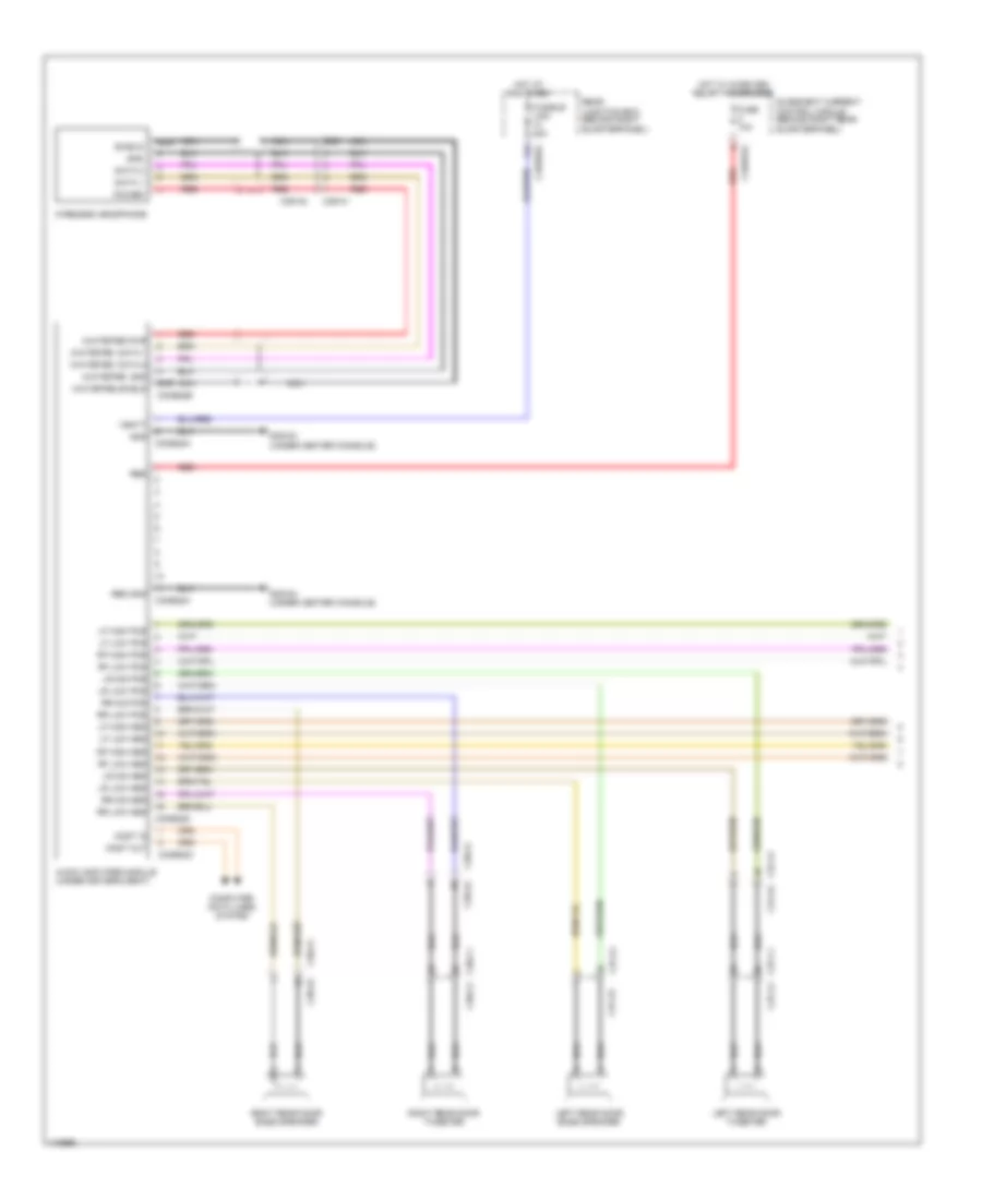
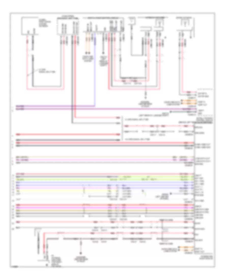
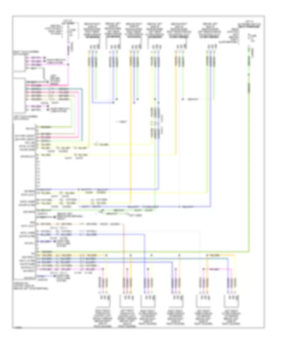
Navigation Wiring Diagram, 8-Speaker System (1 of 5) for Land Rover Range Rover Sport Supercharged 2014
 https://portal-diagnostov.com/license.html
Automotive Electricians Portal FZCO
Automotive Electricians Portal FZCO
https://portal-diagnostov.com/license.html
https://portal-diagnostov.com/license.html
Automotive Electricians Portal FZCO
Automotive Electricians Portal FZCOList of elements for Navigation Wiring Diagram, 8-Speaker System (1 of 5) for Land Rover Range Rover Sport Supercharged 2014:
- Audio amplifier module (under driver's seat)
- C29-a1
- C29-a2
- C37-a1
- C37-a1 c37-a2
- C37-a2
- C37-c1 c37-c2
- C38-a1
- C38-a2
- C38-c1 c38-c2
- C3me22a
- C3me22b
- C3me22c
- C3me22d
- C3me22h
- C4br01a
- C4br02a
- Computer data lines system
- Data 1
- Data 2
- Fuse 10a
- Fusible link 40a
- G3d161 (under center console)
- Gnd
- Hot at all times
- Hot w/ micro re1 relay 1 energized
- Left rear door bass speaker
- Left rear door tweeter
- Lf high pos
- Lf low pos
- Lr low pos
- Lr mid pos
- Most in
- Most out
- Nca
- Power
- Quiescent current control module (behind right rear quarterpanel)
- Rbd
- Rbd gnd
- Rear junction box (behind right quarterpanel)
- Red
- Rf high pos
- Rf low pos
- Right rear door bass speaker
- Right rear door tweeter
- Rr low pos
- Rr mid pos
- Scr
- Shield
- Vbatt
- Whitefire data 1
- Whitefire data 2
- Whitefire gnd
- Whitefire pwr
- Whitefire shield
- Wireless headphone
Navigation Wiring Diagram, 8-Speaker System (2 of 5) for Land Rover Range Rover Sport Supercharged 2014
 https://portal-diagnostov.com/license.html
Automotive Electricians Portal FZCO
Automotive Electricians Portal FZCO
https://portal-diagnostov.com/license.html
https://portal-diagnostov.com/license.html
Automotive Electricians Portal FZCO
Automotive Electricians Portal FZCOList of elements for Navigation Wiring Diagram, 8-Speaker System (2 of 5) for Land Rover Range Rover Sport Supercharged 2014:
- (left side of steering column) steering wheel module
- Audio ladder
- Audio ladder rtn
- C2r115b
- C3a-a1
- C3a-a2
- C3b-a1
- C3b-a2
- Clock spring (top of steering column)
- Computer data lines system
- Down/back switch
- Forward/up switch
- G2d216 (right center of dash)
- Gnd
- Hs can h
- Hs can l
- Ice 1
- Ice 2
- Left front door bass speaker
- Left front tweeter
- Left steering wheel switchpack
- Logic gnd
- Nca
- Radio phone switch
- Right front door bass speaker
- Right front tweeter
- Voice switch
- Volume + switch
- Volume - switch
Navigation Wiring Diagram, 8-Speaker System (3 of 5) for Land Rover Range Rover Sport Supercharged 2014
 https://portal-diagnostov.com/license.html
Automotive Electricians Portal FZCO
Automotive Electricians Portal FZCO
https://portal-diagnostov.com/license.html
https://portal-diagnostov.com/license.html
Automotive Electricians Portal FZCO
Automotive Electricians Portal FZCOList of elements for Navigation Wiring Diagram, 8-Speaker System (3 of 5) for Land Rover Range Rover Sport Supercharged 2014:
- Am/fm antenna amplifier (top left side of tailgate)
- C29-b1
- C29-b2
- C2mc01b
- C2mc01c
- C2mc02a
- C2mc02b
- C2mc02c
- C2mc02d
- C2mc02e
- C2mc02f
- C2mc02i
- C2mc02j
- C2me14
- C2me14a
- C2me14b
- C32-d1
- C32-d2
- C32-f1 c32-f2
- C32-n1
- C32-n2
- C4br01a
- C9me115
- C9me115a
- Camera shield
- Camera video
- Computer data lines system
- Ferrite core
- Front overhead console
- Fuse 10a
- Fuse 15a
- G2d215 (right center of dash)
- G2d284 (left center of dash)
- G4d480bl (center rear of roof)
- Gnd
- Gnd 1
- Gnd 2
- Hot w/ micro re1 relay 1 energized
- Iam cvbs gnd
- Iam cvbs in
- Instrument cluster
- Integrated control panel
- Lvds pos
- Lvds scr
- Mic+
- Mic-
- Most in
- Most out
- Ms can h
- Ms can l
- Navigation system
- Nca
- Pwr
- Quiescent current control module (qccm) (behind right rear quarterpanel)
- Rear seat entertainment circuit
- Red
- Rse cvbs gnd
- Rse cvbs sig
- Scn
- Scr
- Sig
- Sply 1
- Sply 2
- Sw audio switch
- Touch screen
- Vbatt
- W/ telephone interface module
- W/o telephone interface module
Navigation Wiring Diagram, 8-Speaker System (4 of 5) for Land Rover Range Rover Sport Supercharged 2014
 https://portal-diagnostov.com/license.html
Automotive Electricians Portal FZCO
Automotive Electricians Portal FZCO
https://portal-diagnostov.com/license.html
https://portal-diagnostov.com/license.html
Automotive Electricians Portal FZCO
Automotive Electricians Portal FZCOList of elements for Navigation Wiring Diagram, 8-Speaker System (4 of 5) for Land Rover Range Rover Sport Supercharged 2014:
- (if equipped) telephone interface module
- (or red)
- Av input panel
- C23-a1
- C23-a2
- C23-c1
- C23-c2
- C2mm25a
- C2mm25b
- C2mm25d
- C2mm25e
- C2mm25f
- C32-m1
- C32-m2
- C3me37a
- C3me37b
- Computer data lines system
- Diag +
- Diag -
- Diag rtn
- Diag send
- G2d284 (left center of dash)
- G3d362 (under right rear seat)
- Global positioning system antenna
- Gnd
- Gnd b-
- Illum +
- Illum -
- Interior lights system
- Lh pos
- Ms can h
- Ms can l
- Nca
- Red
- Rh pos
- Scr
- Scrn
- Shield
- Sig
- Usb data pos
- Usb gnd
- Usb pos
- Usb scr
- Vbatt
- W/ telephone interface module
- W/o gps signal splitter
- W/o telephone interface module
Navigation Wiring Diagram, 8-Speaker System (5 of 5) for Land Rover Range Rover Sport Supercharged 2014
 https://portal-diagnostov.com/license.html
Automotive Electricians Portal FZCO
Automotive Electricians Portal FZCO
https://portal-diagnostov.com/license.html
https://portal-diagnostov.com/license.html
Automotive Electricians Portal FZCO
Automotive Electricians Portal FZCOList of elements for Navigation Wiring Diagram, 8-Speaker System (5 of 5) for Land Rover Range Rover Sport Supercharged 2014:
- (if equipped) gps signal splitter
- (or red)
- Am-fm
- Am-fm scn
- Ant amp
- Antenna amplifier
- Aux1 l +
- Aux1 l r-
- Aux1 r +
- Band 3 ant gnd
- Band l ant band l ant
- C23-a1
- C23-a2
- C2me03a
- C2me03d
- C2me03e
- C2me03f
- C2me03g
- C2me03h
- C32-aa1
- C32-aa2
- C32-c1
- C32-c2
- C32-ga1
- C32-ga2
- C32-v1
- C32-v2
- C44-w1
- C44-w2
- C44-x1
- C44-x2
- C44-y1a
- C44-y2a
- C44-z1
- C44-z2
- C4me192a
- C4me192b
- C4me24a
- C4me24b
- C4me24c
- C4me41a
- C4me41b
- C4me41c
- C9me116b
- C9me46b
- C9me46c
- Computer data lines system
- Cvbs video out
- Cvbs video scn
- Digital radio control module
- Ferrite core
- Fm antenna amplifier (top right side of tailgate)
- Fm2
- Fm2 scn c2me03c
- G2d284 (left center of dash)
- G3d172 (left rear of luggage compt)
- G4d480bl (center rear of roof)
- G4d480br (center rear of roof)
- Global positioning system antenna
- Gnd
- Gnd band 3 ant
- Gps in gnd
- Gps in sig
- Gps out gnd
- Gps out sig
- Gps scrn
- Gps sig
- Integrated audio module
- Lvds data out+
- Lvds data out-
- Mic 1 pos
- Most in
- Most out
- Nca
- Pwr gnd
- Red
- Sat rf gnd
- Sat rf in
- Satellite radio control module (behind left rear quarterpanel)
- Scn
- Scr
- Scr gnd
- Scrn
- Sdars antenna
- Sig
- Usb 5v
- Usb data pos
- Usb gnd
- Usb scr
- Vbatt
- W/ gps signal splitter
- W/o gps signal splitter
Parking Assistant Wiring Diagram, with SWC for Land Rover Range Rover Sport Supercharged 2014
 https://portal-diagnostov.com/license.html
Automotive Electricians Portal FZCO
Automotive Electricians Portal FZCO
https://portal-diagnostov.com/license.html
https://portal-diagnostov.com/license.html
Automotive Electricians Portal FZCO
Automotive Electricians Portal FZCOList of elements for Parking Assistant Wiring Diagram, with SWC for Land Rover Range Rover Sport Supercharged 2014:
- (behind left end of rear bumper)
- (behind left rear quarterpanel) g3d347
- (behind left side of rear bumper) left rear inner parking aid sensor
- (behind left side of rear bumper) left rear outer parking aid sensor
- (behind right end of rear bumper) right rear parking aid control slot detect sensor
- (behind right side of rear bumper) right rear inner parking aid sensor
- (behind right side of rear bumper) right rear outer parking aid sensor
- (left center of dash) g2d284
- C11-b1 c11-b2
- C11-b2 c11-b1
- C2bp01c
- C31-e1 c31-e2
- C31-e2 c31-e1
- C31-l1 c31-l2
- C32-n1
- C32-n2
- C3mp01a
- C3mp01b
- C43-b1
- C43-bb2
- C44-f1
- C44-f2
- C4br02a
- Central junction box (right end of dash)
- Computer data
- Computer data lines system
- Fuse 10a
- Fuse 5a
- Gnd
- Gnd front
- Gnd rear
- Hot at all times
- Hot w/ extended ignition relay energized
- Hs can h
- Hs can l
- Ign
- Ign front
- Ign rear
- Led park assist
- Left front inner parking aid sensor (behind left side of front bumper)
- Left front outer parking aid sensor (behind left side of front bumper)
- Left front parking aid control slot detect sensor (behind left end of front bumper)
- Left rear parking aid control slot detect sensor
- Left touch screen switchpack
- Lines system
- Parking aid control module (behind left quarterpanel)
- Pdc led
- Pdc sw
- Rear junction box (behind right quarterpanel)
- Right front inner parking aid sensor (behind right side of front bumper)
- Right front outer parking aid sensor (behind right side of front bumper)
- Right front parking aid control slot detect sensor (behind right end of front bumper)
- Right touch screen switchpack
- Sig
- Sig fl inner
- Sig fl outer
- Sig fl slot
- Sig fr inner
- Sig fr outer
- Sig fr slot
- Sig rl inner
- Sig rl outer
- Sig rl slot
- Sig rr inner
- Sig rr outer
- Sig rr slot
- Sw park assist
Parking Assistant Wiring Diagram, without SWC for Land Rover Range Rover Sport Supercharged 2014
 https://portal-diagnostov.com/license.html
Automotive Electricians Portal FZCO
Automotive Electricians Portal FZCO
https://portal-diagnostov.com/license.html
https://portal-diagnostov.com/license.html
Automotive Electricians Portal FZCO
Automotive Electricians Portal FZCOList of elements for Parking Assistant Wiring Diagram, without SWC for Land Rover Range Rover Sport Supercharged 2014:
- (behind left end of rear bumper) left rear parking aid control slot detect sensor
- (behind left rear quarterpanel) g3d347
- (behind left side of rear bumper) left rear inner parking aid sensor
- (behind left side of rear bumper) left rear outer parking aid sensor
- (behind right end of rear bumper) right rear parking aid control slot detect sensor
- (behind right side of rear bumper) right rear inner parking aid sensor
- (behind right side of rear bumper) right rear outer parking aid sensor
- (left center of dash) g2d284
- (not used)
- 7-seat
- C11-b1 c11-b2
- C2bp01c
- C31-e1 c31-e2
- C31-l1 c31-l2
- C32-n1
- C32-n2
- C3mp01a
- C3mp01b
- C43-b1
- C43-b1 c43-ba2
- C43-ba2
- C44-f1
- C44-f2
- C4br02a
- Central junction box (right end of dash)
- Computer data
- Computer data lines system
- Fuse 10a
- Fuse 5a
- Gnd
- Gnd front
- Gnd rear
- Hot at all times
- Hot w/ extended ignition relay energized
- Hs can h
- Hs can l
- Ign
- Ign front
- Ign rear
- Led park assist
- Left front inner parking aid sensor (behind left side of front bumper)
- Left front outer parking aid sensor (behind left side of front bumper)
- Left front parking aid control slot detect sensor (behind left end of front bumper)
- Left touch screen switchpack
- Lines system
- Parking aid control module (behind left quarterpanel)
- Pdc led
- Pdc sw
- Rear junction box (behind right quarterpanel)
- Right front inner parking aid sensor (behind right side of front bumper)
- Right front outer parking aid sensor (behind right side of front bumper)
- Right front parking aid control slot detect sensor (behind right end of front bumper)
- Right touch screen switchpack
- Sig
- Sig fl inner
- Sig fl outer
- Sig fl slot
- Sig fr inner
- Sig fr outer
- Sig fr slot
- Sig rl inner
- Sig rl outer
- Sig rl slot
- Sig rr inner
- Sig rr outer
- Sig rr slot
- Sw park assist
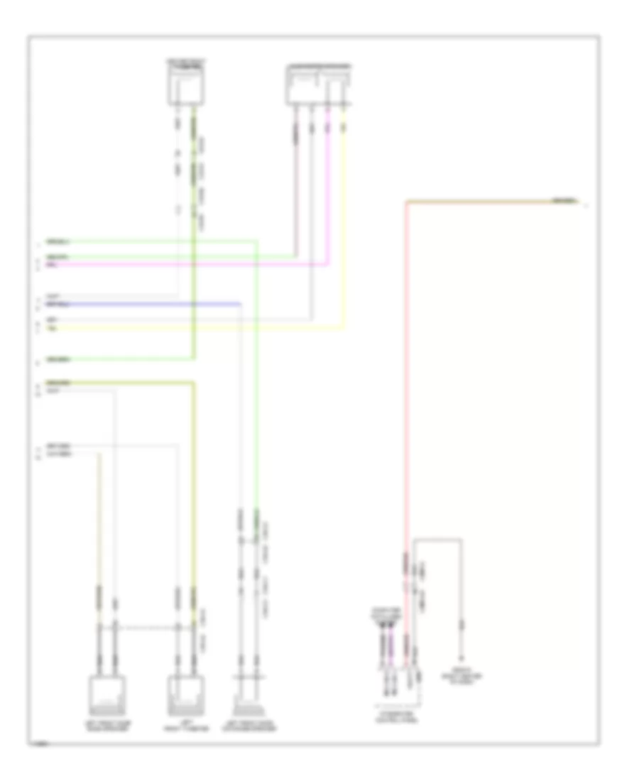
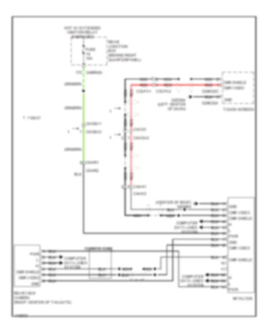
Rear View Camera Wiring Diagram, with SWC for Land Rover Range Rover Sport Supercharged 2014
 https://portal-diagnostov.com/license.html
Automotive Electricians Portal FZCO
Automotive Electricians Portal FZCO
https://portal-diagnostov.com/license.html
https://portal-diagnostov.com/license.html
Automotive Electricians Portal FZCO
Automotive Electricians Portal FZCOList of elements for Rear View Camera Wiring Diagram, with SWC for Land Rover Range Rover Sport Supercharged 2014:
- (right center of tailgate) rear view camera
- C2mc02c
- C32-fa1
- C32-fa2
- C43-b1
- C43-bb2
- C43-d1
- C43-db2
- C4br02a
- Can-h
- Can-l
- Cmr shield
- Cmr video
- Computer data lines system
- Fuse 14 10a
- G4d347 (left "c" pillar)
- Gnd
- Hot w/ extended ignition relay energized
- Nca
- Pwr
- Rear junction box (behind right quarterpanel)
- Red
- Touch screen display
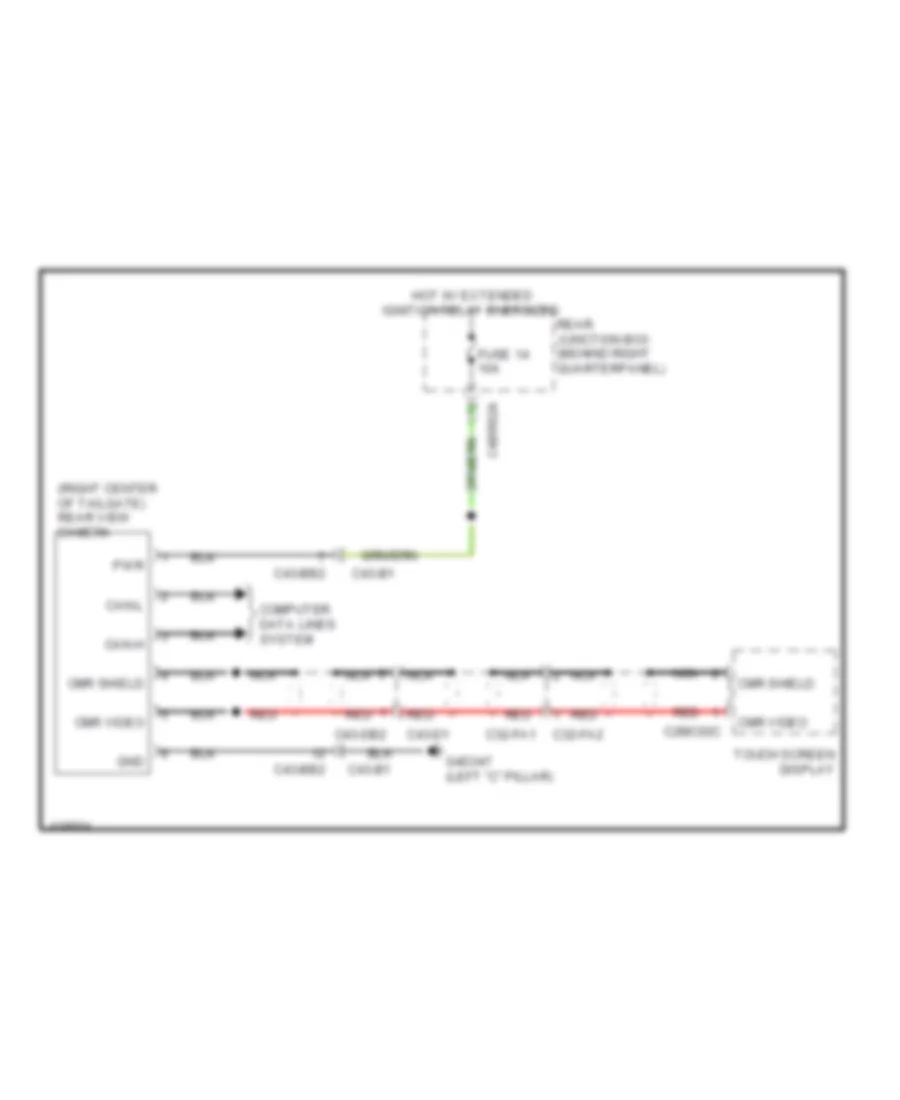
Rear View Camera Wiring Diagram, without SWC for Land Rover Range Rover Sport Supercharged 2014
 https://portal-diagnostov.com/license.html
Automotive Electricians Portal FZCO
Automotive Electricians Portal FZCO
https://portal-diagnostov.com/license.html
https://portal-diagnostov.com/license.html
Automotive Electricians Portal FZCO
Automotive Electricians Portal FZCOList of elements for Rear View Camera Wiring Diagram, without SWC for Land Rover Range Rover Sport Supercharged 2014:
- (center of roof) g4d480
- 7-seat
- C2mc02a
- C2mc02c
- C32-fa1
- C32-fa2
- C43-ba1
- C43-ba2
- C43-d1
- C43-da2
- C44-k1
- C44-k2
- C44-r1
- C44-r2
- C4br02a
- Cmr shield
- Cmr shield cmr video gnd
- Cmr video
- Computer data lines system
- Ferrite core
- Fuse 10a
- G2d284 (left center of dash)
- Gnd
- Hot w/ extended ignition relay energized
- Nca
- Pwr
- Rear junction box (behind right quarterpanel)
- Rear view camera (right center of tailgate)
- Red
- Rf filter
- Touch screen
Telematics Wiring Diagram for Land Rover Range Rover Sport Supercharged 2014
 https://portal-diagnostov.com/license.html
Automotive Electricians Portal FZCO
Automotive Electricians Portal FZCO
https://portal-diagnostov.com/license.html
https://portal-diagnostov.com/license.html
Automotive Electricians Portal FZCO
Automotive Electricians Portal FZCOList of elements for Telematics Wiring Diagram for Land Rover Range Rover Sport Supercharged 2014:
- +5v dc
- 3.0l
- 5.0l sc
- Batt
- Bcall activated led
- Bcall btn backlight
- Body control module (bcm)
- Btn diagnostic o/p
- Btn input common
- C11-m1
- C11-m2
- C12-a1
- C12-a2
- C1e120a
- C1e121a
- C29-b1
- C29-b2
- C2bp01a
- C31-l1
- C31-l2
- C32-d1
- C32-d2
- C32-g1
- C32-g2
- C32-j1
- C32-j2
- C33-y1
- C33-y2
- C39-a1
- C39-a2
- C3r114b
- C4br02a
- C4me192a
- C4me192c
- C4mt01a
- C4mt01b
- C4mt01c
- C4mt01d
- C9ln28
- C9ln28a
- Central junction box (right end of dash)
- Computer data lines system
- Crash sig
- Data +
- Data -
- Diagnostic 1
- Diagnostic 2
- Ecall + bcall btn
- Ecall activated led
- Ecall btn backlight
- Engine control module (ecm) (left rear of engine compt)
- Ens
- Front overhead console
- Fuse 15a
- G2d216 (right center of dash)
- Global positioning antenna system
- Gnd
- Gnd screen
- Gps scrn
- Gps sig
- Gps signal splitter
- Gsm antenna
- Hot at all times
- Hs can-h
- Hs can-l
- Integrated audio module
- J-f-crash
- Led o/p common
- Mbm ant sig
- Mic +
- Mic -
- Mic 1 pos
- Ms can-h
- Ms can-l
- Nca
- Rear junction box (behind right quarterpanel)
- Red
- Restraints control module (under front of center console)
- Scr
- Sig
- Speaker +
- Speaker -
- Telematics module (under left side of dash)
- Telematics speaker
- Usb sim wi-fi module (under left side of dash)
- W/ gps signal splitter
- W/o gps signal splitter
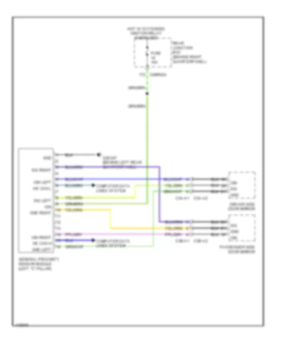
Vehicle Proximity Notification Wiring Diagram for Land Rover Range Rover Sport Supercharged 2014
 https://portal-diagnostov.com/license.html
Automotive Electricians Portal FZCO
Automotive Electricians Portal FZCO
https://portal-diagnostov.com/license.html
https://portal-diagnostov.com/license.html
Automotive Electricians Portal FZCO
Automotive Electricians Portal FZCOList of elements for Vehicle Proximity Notification Wiring Diagram for Land Rover Range Rover Sport Supercharged 2014:
- C3a-a1 c3a-a2
- C3b-a2 c3b-a1
- C4br02a
- Computer data lines system
- Driver side door mirror
- Fuse 10a
- G3d347 (behind left rear quarterpanel)
- General proximity sensor module (left "c" pillar)
- Gnd
- Gnd left
- Gnd right
- Hot w/ extended ignition relay energized
- Hs can h
- Hs can l
- Ign
- Ign left
- Ign right
- Passenger side door mirror
- Rear junction box (behind right quarterpanel)
- Sig
- Sig left
- Sig right

 Čeština
 Dansk
Dansk Deutsch
 Ελληνικά
 English
 English
 Español
 Suomi
Suomi Français
 Français
 עברית
עברית Hrvatski
 Magyar
 Italiano
 한국어
한국어 Nederlands
 Polski
 Português
 Português
 Română
 Русский
 Slovenčina
 Slovenščina
 Svenska
 Türkçe
 中文 (中国)
