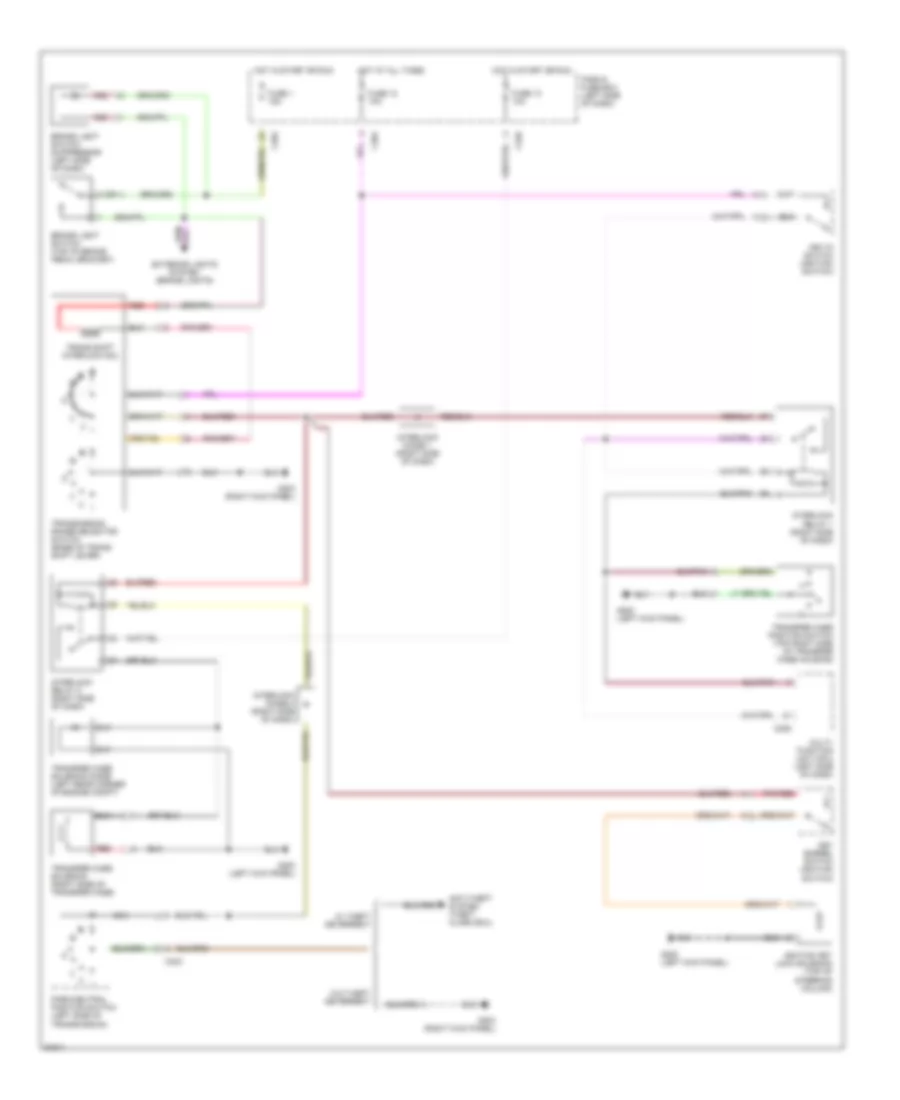
SHIFT INTERLOCKS
Shift Interlock Wiring Diagram for Land Rover Discovery SE7 1996
 https://portal-diagnostov.com/license.html
Automotive Electricians Portal FZCO
Automotive Electricians Portal FZCO
https://portal-diagnostov.com/license.html
https://portal-diagnostov.com/license.html
Automotive Electricians Portal FZCO
Automotive Electricians Portal FZCO
List of elements for Shift Interlock Wiring Diagram for Land Rover Discovery SE7 1996:
- 2 (or 1)
- Anti-theft system (theft alarm ecu)
- Brake light switch (top of brake pedal bracket)
- Brake light switch suppressor (left side of dash)
- C204
- C205
- C226
- C323
- Exterior lights system (brake lights)
- Fascia fuse box (left side of dash)
- Fuse 1 15a
- Fuse 12 10a
- Fuse 13 10a
- G200 (left kick panel)
- G203 (right kick panel)
- Hot at all times
- Hot in start or run
- Ignition key lock solenoid (top of steering column)
- Interlock diode 1 (right side of dash)
- Interlock diode 2 (right side of dash)
- Interlock relay 1 (right side of dash)
- Interlock relay 2 (right side of dash)
- Key barrel switch (ignition switch)
- Key-in switch (ignition switch)
- Multi- function unit (mfu) (left side of dash)
- Nca
- Park/neutral position switch (left side of transmission)
- Pnk/red
- Red
- Trans shift interlock sol
- Transfer case position switch (top right side of transfer case housing)
- Transfer case solenoid (right side of transfer case)
- Transfer case solenoid diode (left rear corner of engine compt)
- Transmission range selector switch (base of trans shift lever)
- W/ theft deterrent
- W/o theft deterrent
 Čeština
 Dansk
Dansk Deutsch
 Ελληνικά
 English
 English
 Español
 Suomi
Suomi Français
 Français
 עברית
עברית Hrvatski
 Magyar
 Italiano
 한국어
한국어 Nederlands
 Polski
 Português
 Português
 Română
 Русский
 Slovenčina
 Slovenščina
 Svenska
 Türkçe
 中文 (中国)
 日本語
日本語
