ANTI-LOCK BRAKES
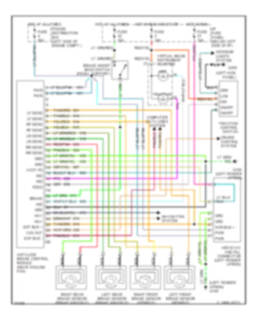
Anti-lock Brake Wiring Diagrams for Lincoln Continental 1995
 https://portal-diagnostov.com/license.html
Automotive Electricians Portal FZCO
Automotive Electricians Portal FZCO
https://portal-diagnostov.com/license.html
https://portal-diagnostov.com/license.html
Automotive Electricians Portal FZCO
Automotive Electricians Portal FZCO
List of elements for Anti-lock Brake Wiring Diagrams for Lincoln Continental 1995:
- (left fender apron) g100
- (left kick panel)
- Abs
- Abs evac and fill connector (left fender apron)
- Accy fd
- Anti-lock brake control module (near cooling fan)
- Brake
- Brake on/off (boo) switch (pedal support)
- C 1995 vftc
- Computer data lines system
- Cruise control system
- Feed
- Fuse 10a
- Fuse 60a
- G100 (left fender apron)
- G200
- Grd
- Hot at all times
- Hot in run
- Hot in run and start
- I/p fuse panel (below left side of i/p)
- Ign
- Ind
- Interior lights system
- Lcm
- Left front brake sensor (spindle)
- Left rear brake sensor (brake knuckle)
- Lf sens
- Lr sens
- Nav
- Navigation system
- Nca
- On/off
- Power distribution box (left side of engine compt.)
- Pwr
- Red/pnk
- Rf sens
- Right front brake sensor (spindle)
- Right rear brake sensor (brake knuckle)
- Rr sens
- Scp bus +
- Scp bus -
- Scr bus +
- Traction
- Traction control switch
- Virtual image instrument cluster
- Vss out
 Čeština
 Dansk
Dansk Deutsch
 Ελληνικά
 English
 English
 Español
 Suomi
Suomi Français
 Français
 עברית
עברית Hrvatski
 Magyar
 Italiano
 한국어
한국어 Nederlands
 Polski
 Português
 Português
 Română
 Русский
 Slovenčina
 Slovenščina
 Svenska
 Türkçe
 中文 (中国)
 日本語
日本語
