ENGINE PERFORMANCE
5.4L
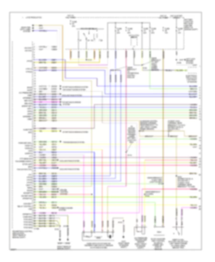
5.4L, Engine Performance Wiring Diagram (1 of 4) for Lincoln Navigator L 2007
 https://portal-diagnostov.com/license.html
Automotive Electricians Portal FZCO
Automotive Electricians Portal FZCO
https://portal-diagnostov.com/license.html
https://portal-diagnostov.com/license.html
Automotive Electricians Portal FZCO
Automotive Electricians Portal FZCO
List of elements for 5.4L, Engine Performance Wiring Diagram (1 of 4) for Lincoln Navigator L 2007:
- (in body main harness, near breakout to c212) (expedition el & navigator l) s267
- (in engine control sensor harness, near breakout to left front wheel speed sensor) s129
- (in engine control sensor harness, under battery junction box)
- (near breakout to battery junction box) s112
- (near breakout to horn) s122
- (near breakout to left front wheel speed sensor)
- (near breakout to powertrain control module)
- (right rear of engine compt)
- 10a
- 20a
- 30a
- A/c clutch relay
- A/c pressure
- A/c pressure transducer sensor (right front of engine compt)
- Accr
- Air conditioning system
- Anti-lock brakes system
- App1
- App2
- App3
- Appsref1
- Appsref2
- Appsrtn1
- Appsrtn2
- Battery junction box (bjb) (center front of engine compt)
- Bps
- C175b
- Canvent
- Case gnd
- Cbb71
- Cbb76
- Cdb08
- Cdc10
- Cdc12
- Cdc15
- Cdc35
- Cdc38
- Ce105
- Ce114
- Ce132
- Ce226
- Ce233
- Ce234
- Ce414
- Ce415
- Ce509
- Ce607
- Ce608
- Cet40
- Ch302
- Ch421
- Cl517
- Computer data lines system
- Cooling fans system
- Cruise control system
- Electronic fan clutch (top front of engine)
- Evap canister vent control solenoid (under left side of vehicle)
- Fan motor ctrl
- Fan speed signal
- Feps
- Ftp sens sig
- Fuse
- G107
- G107 (right rear of engine compt)
- G108
- Gd113
- Gen com
- Gen mon
- Ho2s-12
- Ho2s-22
- Hot at all times
- Hot in start or run
- Hs can+
- Hs can-
- Htr-12
- Htr-22
- Iat
- Inertia fuel shutoff (ifs) switch (left rear corner of cargo area, behind trim)
- Injector
- Late production
- Le136
- Le137
- Le230
- Le423
- Maf
- Mafrtn
- Mass air flow/intake air temperature (maf/iat) sensor (in intake system)
- Nca
- Park/netural
- Pcm power relay
- Powertrain control module (pcm) (right rear of engine compt)
- Pwr gnd
- Re136
- Re137
- Re320
- Re407
- Re508
- Relay control
- S101
- S102
- S103
- S106
- S115
- S120
- S156
- S442 (expedition el & navigator l) (in body main harness, near breakout to c465)
- Sbb36
- Sccs
- Sccsrtn
- Sig return
- Smc
- Smcs
- Smr/start
- Starting/charging system
- Stoplamp
- Transmissions system
- Vbatt
- Vdb04
- Vdb05
- Ve510
- Ve518
- Ve731
- Ve733
- Ve740
- Ve807
- Ve822
- Ve922
- Vec03
- Vec10
- Vmv
- Vpwr
- Vref
- Vss
- Wiper/washer system
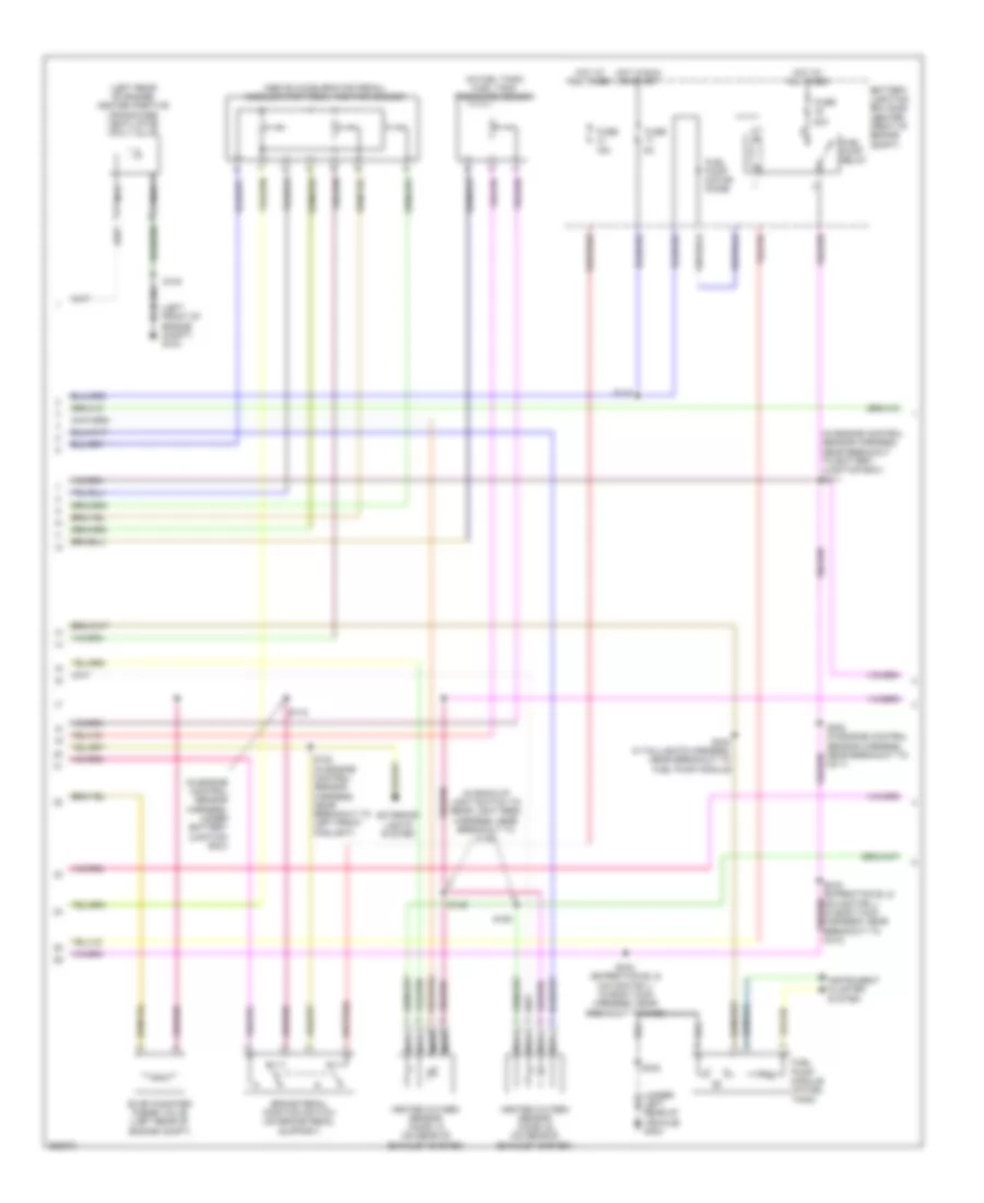
5.4L, Engine Performance Wiring Diagram (2 of 4) for Lincoln Navigator L 2007
 https://portal-diagnostov.com/license.html
Automotive Electricians Portal FZCO
Automotive Electricians Portal FZCO
https://portal-diagnostov.com/license.html
https://portal-diagnostov.com/license.html
Automotive Electricians Portal FZCO
Automotive Electricians Portal FZCOList of elements for 5.4L, Engine Performance Wiring Diagram (2 of 4) for Lincoln Navigator L 2007:
- (above accelerator pedal) accelerator pedal position sensor
- (in back-up light switch to rear light feed harness, near breakout to c146)
- (in engine control sensor harness, near breakout to battery junction box) s111
- (in engine control sensor harness, under battery junction box)
- (in fuel tank) fuel tank pressure sensor
- (left front of engine compt) g103
- (left rear of engine) heated positive crankcase ventilation (pcv) valve
- (under left rear of vehicle) g404
- 15a
- 20a
- Battery junction box (bjb) (center front of engine compt)
- Brake pedal position switch (on brake pedal support)
- C211)
- Evap canister purge valve (left rear of engine compt)
- Exterior lights system
- Fuel pump module (in fuel tank)
- Fuel pump motor diode
- Fuel pump relay
- Fuse
- Heated oxygen sensor (ho2s) 12 (on rear of exhaust system)
- Heated oxygen sensor (ho2s) 22 (on rear of exhaust system)
- Hot at all times
- Hot in run or start
- Instrument cluster system
- Nca
- S115
- S116
- S124 (in engine control sensor harness, near breakout to left front foglight)
- S140
- S149
- S150
- S433
- S434 in taillights harness, near breakout to fuel pump module
- S443 (expedition el & navigator l) (in body main harness, near breakout to c405)
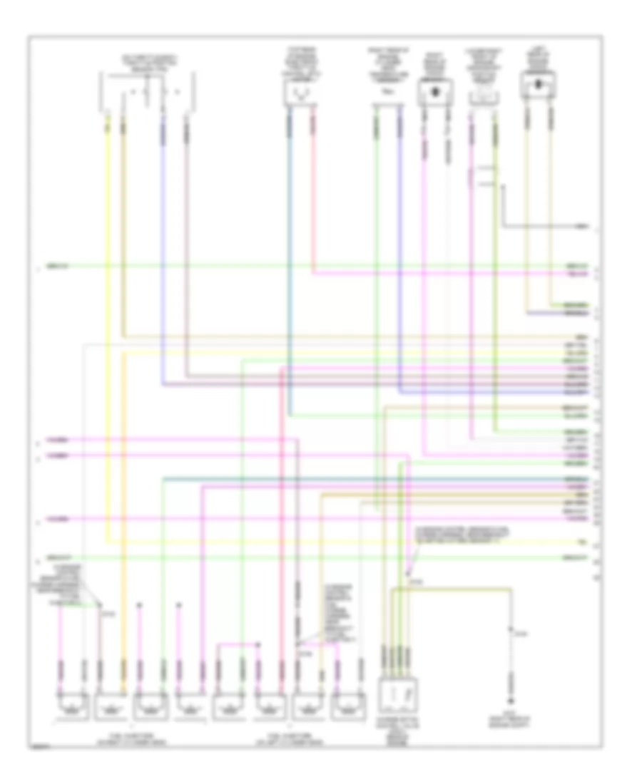
5.4L, Engine Performance Wiring Diagram (3 of 4) for Lincoln Navigator L 2007
 https://portal-diagnostov.com/license.html
Automotive Electricians Portal FZCO
Automotive Electricians Portal FZCO
https://portal-diagnostov.com/license.html
https://portal-diagnostov.com/license.html
Automotive Electricians Portal FZCO
Automotive Electricians Portal FZCOList of elements for 5.4L, Engine Performance Wiring Diagram (3 of 4) for Lincoln Navigator L 2007:
- (in engine control sensor & fuel charge harness, near breakout to fuel injector 3)
- (in engine control sensor & fuel charge harness, near breakout to fuel injector 7)
- (in engine control sensor & fuel charge harness, near breakout to heated oxygen sensor 11)
- (left rear of engine) knock sensor 2
- (lower right front of engine) crankshaft position sensor
- (on throttle body) throttle position sensor (tps)
- (right rear of engine) cylinder head temperature sensor
- (right rear of engine) knock sensor 1
- (top rear of engine) electronic throttle control (etc) motor
- Charge motion control valve (cmcv) (rear of engine)
- Fuel injectors (on left cylinder head)
- Fuel injectors (on right cylinder head)
- G107 (right rear of engine compt)
- Nca
- S136
- S138
- S140
- S142
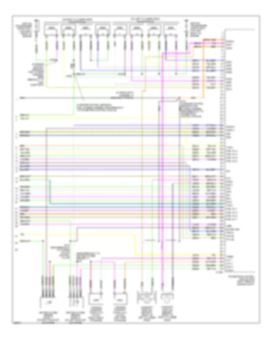
5.4L, Engine Performance Wiring Diagram (4 of 4) for Lincoln Navigator L 2007
 https://portal-diagnostov.com/license.html
Automotive Electricians Portal FZCO
Automotive Electricians Portal FZCO
https://portal-diagnostov.com/license.html
https://portal-diagnostov.com/license.html
Automotive Electricians Portal FZCO
Automotive Electricians Portal FZCOList of elements for 5.4L, Engine Performance Wiring Diagram (4 of 4) for Lincoln Navigator L 2007:
- (in engine control sensor & fuel charge harness, near breakout to fuel injector 3)
- (in engine control sensor & fuel charge harness, near breakout to powertrain control module)
- (in headlights harness, in breakout to c133)
- (near breakout to heated oxygen sensor 11) s138
- (on left cylinder head) coils on plug
- (on right cylinder head) coils on plug
- C175e
- Camshaft position sensor 1 (front of right cylinder bank)
- Camshaft position sensor 2 (front of left cylinder head)
- Cd1a
- Cd2d
- Cd3b
- Cd4g
- Cd5f
- Cd6f
- Cd7c
- Cd8h
- Ce123
- Ce124
- Ce125
- Ce126
- Ce127
- Ce128
- Ce205
- Ce206
- Ce207
- Ce208
- Ce209
- Ce210
- Ce211
- Ce212
- Ce235
- Ce236
- Ce309
- Ce310
- Ce411
- Ce412
- Ce422
- Ce426
- Ce918
- Cht
- Ckp+
- Ckp-
- Cmcv
- Cmp1+
- Cmp1-
- Cmp2+
- Cmp2-
- Cvm
- De706
- Fuel inj 1
- Fuel inj 2
- Fuel inj 3
- Fuel inj 4
- Fuel inj 5
- Fuel inj 6
- Fuel inj 7
- Fuel inj 8
- Heated oxygen sensor (ho2s) 11 (on right exhaust downpipe)
- Heated oxygen sensor (ho2s) 21 (on left exhaust downpipe)
- Ho2s-11
- Ho2s-21
- Htr-11
- Htr-21
- Ignition transformer capacitor 1 (top right front of engine)
- Ignition transformer capacitor 2 (top left front of engine)
- Ks1+
- Ks1-
- Ks2+
- Ks2-
- Le134
- Le135
- Nca
- Powertrain control module (pcm) (right rear of engine compt)
- Re134
- Re135
- Re143
- Re144
- Re323
- Re324
- Re405
- S135
- S137 near breakout to charge motion control valve)
- S139
- S141 (in engine control sensor & fuel nca charge harness, near breakout to powertrain control module)
- S143
- Shield
- Sig return
- Tacm+
- Tacm-
- Tp1 ns
- Tp2 ps
- Tpref
- Tprtn
- Variable camshaft timing (vct) valve 1 (right front of engine)
- Variable camshaft timing (vct) valve 2 (left side of engine)
- Vct 1
- Vct 2
- Ve706
- Ve707
- Ve712
- Ve735
- Ve737
- Ve801
- Ve802
- Ve818
- Ve819
- Vh433
- Vref

 Čeština
 Dansk
Dansk Deutsch
 Ελληνικά
 English
 English
 Español
 Suomi
Suomi Français
 Français
 עברית
עברית Hrvatski
 Magyar
 Italiano
 한국어
한국어 Nederlands
 Polski
 Português
 Português
 Română
 Русский
 Slovenčina
 Slovenščina
 Svenska
 Türkçe
 中文 (中国)
