ANTI-LOCK BRAKES
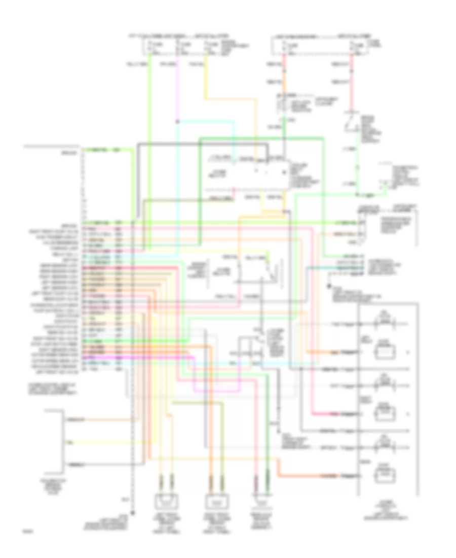
Anti-lock Brake Wiring Diagrams for Ford Bronco 1994
 https://portal-diagnostov.com/license.html
Automotive Electricians Portal FZCO
Automotive Electricians Portal FZCO
https://portal-diagnostov.com/license.html
https://portal-diagnostov.com/license.html
Automotive Electricians Portal FZCO
Automotive Electricians Portal FZCO
List of elements for Anti-lock Brake Wiring Diagrams for Ford Bronco 1994:
- (at left front wheel)
- (at right front wheel)
- 4wabs control module (left front corner of engine compartment)
- 4wabs data link connector (left side of engine compt)
- 4wabs hydraulic unit (left side of engine compartment)
- 4wabs pump motor (left side of engine compt)
- 4wabs relay #1
- 4wabs relay #2
- Accleration sensor (on rear axle)
- Anti-lock brakes indicator
- Brake on/off (boo) switch (on brake pedal support)
- C185
- C250
- C251
- C252
- Chassis rolls databus
- Diag trigger circuit
- Dump valve
- Engine compart- ment fuse box
- Engine compartment fuse box
- Fuse 10a
- Fuse 15a
- Fuse b 30a
- Fuse e 15a
- Fuse h 30a
- Fuse panel
- G-switch #1
- G-switch status
- G101 (front right corner of engine compt)
- G108 (left front of engine compartment on radiator support)
- Ground
- Hot at all times
- Hot in run
- Hot in run or start
- Ignition
- Instrument cluster
- Iso valve
- Left front
- Left front dump valve
- Left front iso valve
- Left front wheel 4wabs sensor
- Left sensor (high)
- Left sensor (low)
- Motor speed sens high
- Motor speed sens low
- Nca
- Pnk
- Powertrain control module (left side of safety wall)
- Programmable speedometer/ odometer module
- Pump motor rly coil (-) g-switch #2
- Rear
- Rear axle sensor (on axle assembly)
- Rear dump valve
- Rear iso valve
- Rear sensor (high)
- Rear sensor (low)
- Red/pnk
- Relay coil (-)
- Right front
- Right front dump valve
- Right front iso valve
- Right front wheel 4wabs sensor
- Right sensor (high)
- Right sensor (low)
- Stop lamp switch feed
- Tan
- Tan/red
- Trailer relay box (in engine compartment fuse box)
- Valve reference
- Vehicle speed sensor
- W/e4od or 4r70w only
- Warning lamp
 Čeština
 Dansk
Dansk Deutsch
 Ελληνικά
 English
 English
 Español
 Suomi
Suomi Français
 Français
 עברית
עברית Hrvatski
 Magyar
 Italiano
 한국어
한국어 Nederlands
 Polski
 Português
 Português
 Română
 Русский
 Slovenčina
 Slovenščina
 Svenska
 Türkçe
 中文 (中国)
 日本語
日本語
