CRUISE CONTROL
4.9L
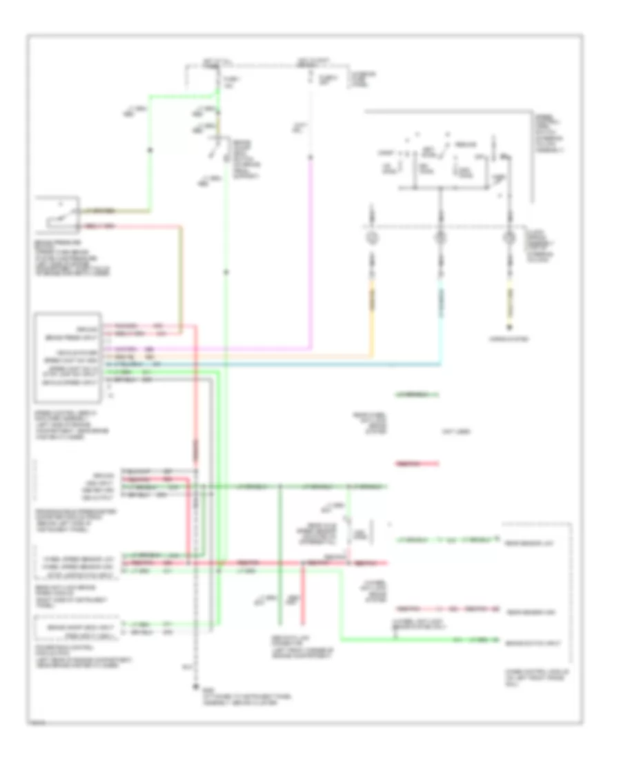
4.9L, Cruise Control Wiring Diagram for Ford Econoline E350 1995
 https://portal-diagnostov.com/license.html
Automotive Electricians Portal FZCO
Automotive Electricians Portal FZCO
https://portal-diagnostov.com/license.html
https://portal-diagnostov.com/license.html
Automotive Electricians Portal FZCO
Automotive Electricians Portal FZCO
List of elements for 4.9L, Cruise Control Wiring Diagram for Ford Econoline E350 1995:
- (attached to instrument panel assembly, behind cluster)
- (behind left side of instrument panel)
- (left front corner of engine compartment)
- (left rear of engine compartment, near brake master cylinder)
- (left side of engine compartment, near brake master cylinder)
- (not used)
- (right side of instrument panel)
- (steering column assembly)
- 15a
- 4-wheel anti-lock brake system
- 4-wheel anti-lock brake system only
- 4wabs control module (on left front frame
- Abs data link connector
- Accel
- Brake on/off (boo) input
- Brake on/off (boo) switch (on brake pedal support)
- Brake press input
- Brake pressure switch (opens when brake
- Brake switch input
- Clock spring assembly (top of steering column)
- Coast
- Dss input
- Dss return
- Fuse 1
- Fuse 6 20a
- G206
- Ground
- Horn
- Horns system
- Hot at all times
- Hot in accy or run
- Interior fuse panel
- Nca
- Off
- Ohms
- Pnk
- Powertrain control module (pcm)
- Programmable speedometer/ odometer module (psom)
- Psom input (vss +)
- Rail)
- Rear anti-lock brake (rabs) module
- Rear axle speed sensor (mounted on differential)
- Rear sensor high
- Rear sensor low
- Rear-wheel anti-lock brake system
- Red
- Red/
- Red/pnk
- Resume
- Set/
- Speed cont sw gnd
- Speed cont sw in stop lamp sw input
- Speed control servo/ amplifier assembly
- Speed control/ horn switch
- Stop lamp switch input
- System has pressure) (left side of engine compartment, in bottom of of brake master cylinder)
- Vehicle power
- Vehicle speed input
- Vss output
- Wheel speed sensor high
- Wheel speed sensor low
5.0L
5.0L, Cruise Control Wiring Diagram for Ford Econoline E350 1995
 https://portal-diagnostov.com/license.html
Automotive Electricians Portal FZCO
Automotive Electricians Portal FZCO
https://portal-diagnostov.com/license.html
https://portal-diagnostov.com/license.html
Automotive Electricians Portal FZCO
Automotive Electricians Portal FZCOList of elements for 5.0L, Cruise Control Wiring Diagram for Ford Econoline E350 1995:
- (attached to instrument panel assembly, behind cluster)
- (behind left side of instrument panel)
- (left front corner of engine compartment)
- (left rear of engine compartment, near brake master cylinder)
- (left side of engine compartment, near brake master cylinder)
- (not used)
- (right side of instrument panel)
- (steering column assembly)
- 15a
- 4-wheel anti-lock brake system
- 4-wheel anti-lock brake system only
- 4wabs control module (on left front frame
- Abs data link connector
- Accel
- Brake on/off (boo) input
- Brake on/off (boo) switch (on brake pedal support)
- Brake press input
- Brake pressure switch (opens when brake
- Brake switch input
- Clock spring assembly (top of steering column)
- Coast
- Dss input
- Dss return
- Fuse 1
- Fuse 6 20a
- G206
- Ground
- Horn
- Horns system
- Hot at all times
- Hot in accy or run
- Interior fuse panel
- Nca
- Off
- Ohms
- Pnk
- Powertrain control module (pcm)
- Programmable speedometer/ odometer module (psom)
- Psom input (vss +)
- Rail)
- Rear anti-lock brake (rabs) module
- Rear axle speed sensor (mounted on differential)
- Rear sensor high
- Rear sensor low
- Rear-wheel anti-lock brake system
- Red
- Red/
- Red/pnk
- Resume
- Set/
- Speed cont sw gnd
- Speed cont sw in stop lamp sw input
- Speed control servo/ amplifier assembly
- Speed control/ horn switch
- Stop lamp switch input
- System has pressure) (left side of engine compartment, in bottom of of brake master cylinder)
- Vehicle power
- Vehicle speed input
- Vss output
- Wheel speed sensor high
- Wheel speed sensor low
5.8L
5.8L, Cruise Control Wiring Diagram for Ford Econoline E350 1995
 https://portal-diagnostov.com/license.html
Automotive Electricians Portal FZCO
Automotive Electricians Portal FZCO
https://portal-diagnostov.com/license.html
https://portal-diagnostov.com/license.html
Automotive Electricians Portal FZCO
Automotive Electricians Portal FZCOList of elements for 5.8L, Cruise Control Wiring Diagram for Ford Econoline E350 1995:
- (attached to instrument panel assembly, behind cluster)
- (behind left side of instrument panel)
- (left front corner of engine compartment)
- (left rear of engine compartment, near brake master cylinder)
- (left side of engine compartment, near brake master cylinder)
- (not used)
- (right side of instrument panel)
- (steering column assembly)
- 15a
- 4-wheel anti-lock brake system
- 4-wheel anti-lock brake system only
- 4wabs control module (on left front frame
- Abs data link connector
- Accel
- Brake on/off (boo) input
- Brake on/off (boo) switch (on brake pedal support)
- Brake press input
- Brake pressure switch (opens when brake
- Brake switch input
- Clock spring assembly (top of steering column)
- Coast
- Dss input
- Dss return
- Fuse 1
- Fuse 6 20a
- G206
- Ground
- Horn
- Horns system
- Hot at all times
- Hot in accy or run
- Interior fuse panel
- Nca
- Off
- Ohms
- Pnk
- Powertrain control module (pcm)
- Programmable speedometer/ odometer module (psom)
- Psom input (vss +)
- Rail)
- Rear anti-lock brake (rabs) module
- Rear axle speed sensor (mounted on differential)
- Rear sensor high
- Rear sensor low
- Rear-wheel anti-lock brake system
- Red
- Red/
- Red/pnk
- Resume
- Set/
- Speed cont sw gnd
- Speed cont sw in stop lamp sw input
- Speed control servo/ amplifier assembly
- Speed control/ horn switch
- Stop lamp switch input
- System has pressure) (left side of engine compartment, in bottom of of brake master cylinder)
- Vehicle power
- Vehicle speed input
- Vss output
- Wheel speed sensor high
- Wheel speed sensor low
7.3L
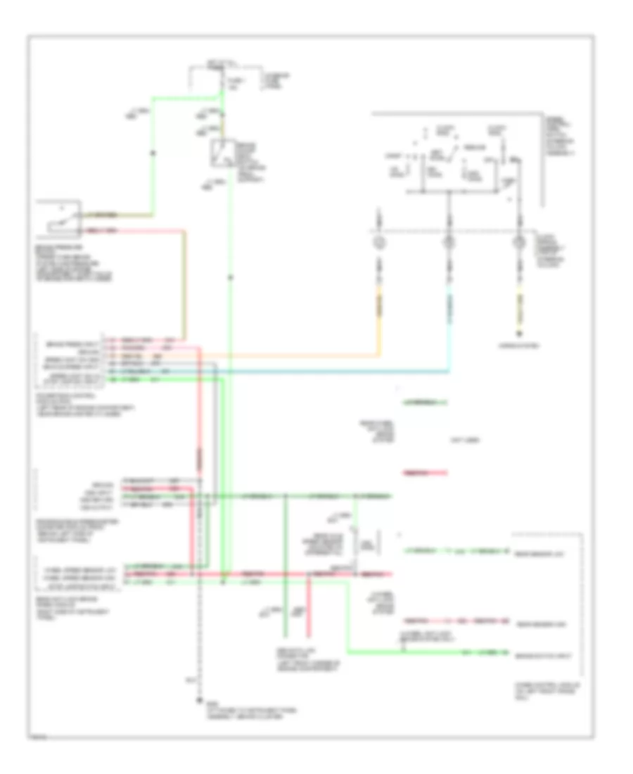
7.3L DI Turbo Diesel, Cruise Control Wiring Diagram for Ford Econoline E350 1995
 https://portal-diagnostov.com/license.html
Automotive Electricians Portal FZCO
Automotive Electricians Portal FZCO
https://portal-diagnostov.com/license.html
https://portal-diagnostov.com/license.html
Automotive Electricians Portal FZCO
Automotive Electricians Portal FZCOList of elements for 7.3L DI Turbo Diesel, Cruise Control Wiring Diagram for Ford Econoline E350 1995:
- (attached to instrument panel assembly, behind cluster)
- (behind left side of instrument panel)
- (left front corner of engine compartment)
- (left rear of engine compartment, near brake master cylinder)
- (not used)
- (right side of instrument panel)
- (steering column assembly)
- 15a
- 4-wheel anti-lock brake system
- 4-wheel anti-lock brake system only
- 4wabs control module (on left front frame
- Abs data link connector
- Accel
- Brake on/off (boo) switch (on brake pedal support)
- Brake press input
- Brake pressure switch (opens when brake
- Brake switch input
- Clock spring assembly (top of steering column)
- Clock- ring
- Coast
- Dss input
- Dss return
- Fuse 1
- G206
- Ground
- Horn
- Horns system
- Hot at all times
- Interior fuse panel
- Nca
- Off
- Ohms
- Pnk
- Powertrain control module (pcm)
- Programmable speedometer/ odometer module (psom)
- Rail)
- Rear anti-lock brake (rabs) module
- Rear axle speed sensor (mounted on differential)
- Rear sensor high
- Rear sensor low
- Rear-wheel anti-lock brake system
- Red
- Red/
- Red/pnk
- Resume
- Set/
- Speed cont sw gnd
- Speed cont sw in stop lamp sw input
- Speed control/ horn switch
- Stop lamp switch input
- System has pressure) (left side of engine compartment, in bottom of of brake master cylinder)
- Vehicle speed input
- Vss output
- Wheel speed sensor high
- Wheel speed sensor low
7.5L
7.5L, Cruise Control Wiring Diagram for Ford Econoline E350 1995
 https://portal-diagnostov.com/license.html
Automotive Electricians Portal FZCO
Automotive Electricians Portal FZCO
https://portal-diagnostov.com/license.html
https://portal-diagnostov.com/license.html
Automotive Electricians Portal FZCO
Automotive Electricians Portal FZCOList of elements for 7.5L, Cruise Control Wiring Diagram for Ford Econoline E350 1995:
- (attached to instrument panel assembly, behind cluster)
- (behind left side of instrument panel)
- (left front corner of engine compartment)
- (left rear of engine compartment, near brake master cylinder)
- (left side of engine compartment, near brake master cylinder)
- (not used)
- (right side of instrument panel)
- (steering column assembly)
- 15a
- 4-wheel anti-lock brake system
- 4-wheel anti-lock brake system only
- 4wabs control module (on left front frame
- Abs data link connector
- Accel
- Brake on/off (boo) input
- Brake on/off (boo) switch (on brake pedal support)
- Brake press input
- Brake pressure switch (opens when brake
- Brake switch input
- Clock spring assembly (top of steering column)
- Coast
- Dss input
- Dss return
- Fuse 1
- Fuse 6 20a
- G206
- Ground
- Horn
- Horns system
- Hot at all times
- Hot in accy or run
- Interior fuse panel
- Nca
- Off
- Ohms
- Pnk
- Powertrain control module (pcm)
- Programmable speedometer/ odometer module (psom)
- Psom input (vss +)
- Rail)
- Rear anti-lock brake (rabs) module
- Rear axle speed sensor (mounted on differential)
- Rear sensor high
- Rear sensor low
- Rear-wheel anti-lock brake system
- Red
- Red/
- Red/pnk
- Resume
- Set/
- Speed cont sw gnd
- Speed cont sw in stop lamp sw input
- Speed control servo/ amplifier assembly
- Speed control/ horn switch
- Stop lamp switch input
- System has pressure) (left side of engine compartment, in bottom of of brake master cylinder)
- Vehicle power
- Vehicle speed input
- Vss output
- Wheel speed sensor high
- Wheel speed sensor low

 Čeština
 Dansk
Dansk Deutsch
 Ελληνικά
 English
 English
 Español
 Suomi
Suomi Français
 Français
 עברית
עברית Hrvatski
 Magyar
 Italiano
 한국어
한국어 Nederlands
 Polski
 Português
 Português
 Română
 Русский
 Slovenčina
 Slovenščina
 Svenska
 Türkçe
 中文 (中国)
