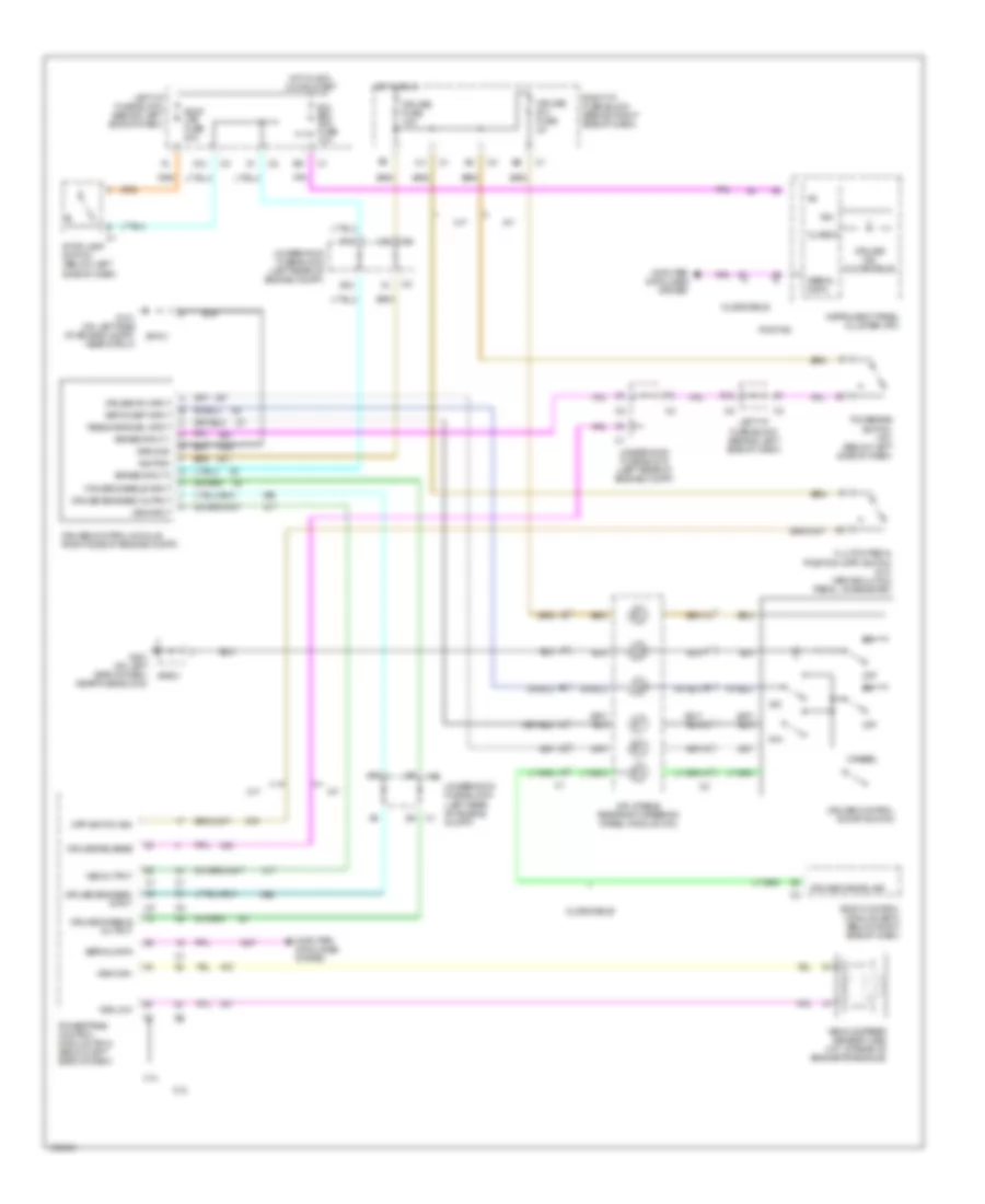
CRUISE CONTROL
Cruise Control Wiring Diagram for Oldsmobile Alero GX 2004
List of elements for Cruise Control Wiring Diagram for Oldsmobile Alero GX 2004:
- 2.2l
- 3.4l
- A/t
- A12
- B12
- B4 c1
- Body control module (bcm) (below right side of dash)
- Brake input 1
- Brake input 2
- Cancel
- Class 2
- Clutch pedal position (cpp) switch (m/t) (above clutch pedal, on bracket)
- Cmputer data lines system
- Cpp switch sig
- Cruise cancel sig
- Cruise control module (right side of engine compt)
- Cruise control on/off switch
- Cruise disable input
- Cruise disable output
- Cruise engaged input
- Cruise engaged output
- Cruise fuse 10a
- Cruise ind (oldsmobile)
- Cruise on input
- Cruise release
- Cruise sw fuse 2a
- F12
- G101 (on left side of engine compt, near strut)
- G201 (on left side of dash, near fuse block)
- Ground
- Hot in acc, on or start
- Hot in run
- Ign
- Ignition
- Inflatable restraint steering wheel module coil
- Instrument panel cluster (ipc)
- Ipc/ bfc acc fuse 10a
- Left i/p fuse block (behind left side of dash)
- M/t
- Off
- Oldsmobile
- Pontiac
- Powertrain control module (pcm) (below left side of dash)
- R/a
- Resume/accel input
- Right i/p fuse block (behind right side of dash)
- S/c
- Serial data
- Set/coast input
- Sp101
- Sp201
- Stop lamp switch (below left side of dash)
- Stop lps fuse 20a
- Tcc/brake switch (a/t) (below left side of dash)
- Underhood fuse block (left rear of engine compt)
- Vehicle speed sensor (vss) (m/t: at rear of engine/transaxle)
- Vss high
- Vss input
- Vss low
- Vss output
 Čeština
 Dansk
Dansk Deutsch
 Ελληνικά
 English
 English
 Español
 Suomi
Suomi Français
 Français
 עברית
עברית Hrvatski
 Magyar
 Italiano
 한국어
한국어 Nederlands
 Polski
 Português
 Português
 Română
 Русский
 Slovenčina
 Slovenščina
 Svenska
 Türkçe
 中文 (中国)
 日本語
日本語