СИСТЕМА ПЕРЕДАЧИ ДАННЫХ
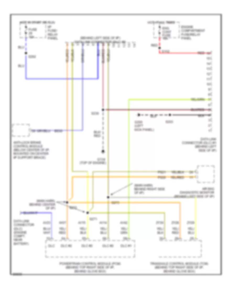
Электросхема компьютерной линии передачи данных CAN для Mercury Villager LS 1997
 https://portal-diagnostov.com/license.html
Automotive Electricians Portal FZCO
Automotive Electricians Portal FZCO
https://portal-diagnostov.com/license.html
https://portal-diagnostov.com/license.html
Automotive Electricians Portal FZCO
Automotive Electricians Portal FZCO
Электросхема компьютерной линии передачи данных CAN для Mercury Villager LS 1997 - Список элементов:
- (behind left side of i/p) data link connector (dlc) #2
- (main harn, behind center of i/p)
- (main harn, behind right side of i/p)
- Air bag diagnostic monitor (behind left side of i/p)
- Anti-lock brake control module (below center of i/p, mounted on center i/p support brace)
- Av07
- Av14
- Av15
- Av23
- Av42
- Bs30
- Data link connector (dlc) #1 (behind left side of i/p)
- Data link connector (dlc) (engine compt, near battery)
- Dlc
- Dlc #1
- Dlc #2
- Eng cont fuse 10a
- Engine compartment fuse/relay panel
- Fuse 10a
- G134 (top of engine)
- G200 (left kick panel)
- Hot at all times
- Hot in start or run
- I/p fuse/ relay panel
- Powertrain control module (pcm) (behind top right side of i/p, behind glove box)
- Ps20
- Ps21
- Red
- S112
- S203
- S230
- S262
- S271
- S272
- S273
- Transaxle control module (tcm) (behind top right side of i/p, behind glove box)
- Zy28
- Zy29
- Zy30
 Čeština
 Dansk
Dansk Deutsch
 Ελληνικά
 English
 English
 Español
 Suomi
Suomi Français
 Français
 עברית
עברית Hrvatski
 Magyar
 Italiano
 한국어
한국어 Nederlands
 Polski
 Português
 Português
 Română
 Русский
 Slovenčina
 Slovenščina
 Svenska
 Türkçe
 中文 (中国)
 日本語
日本語
