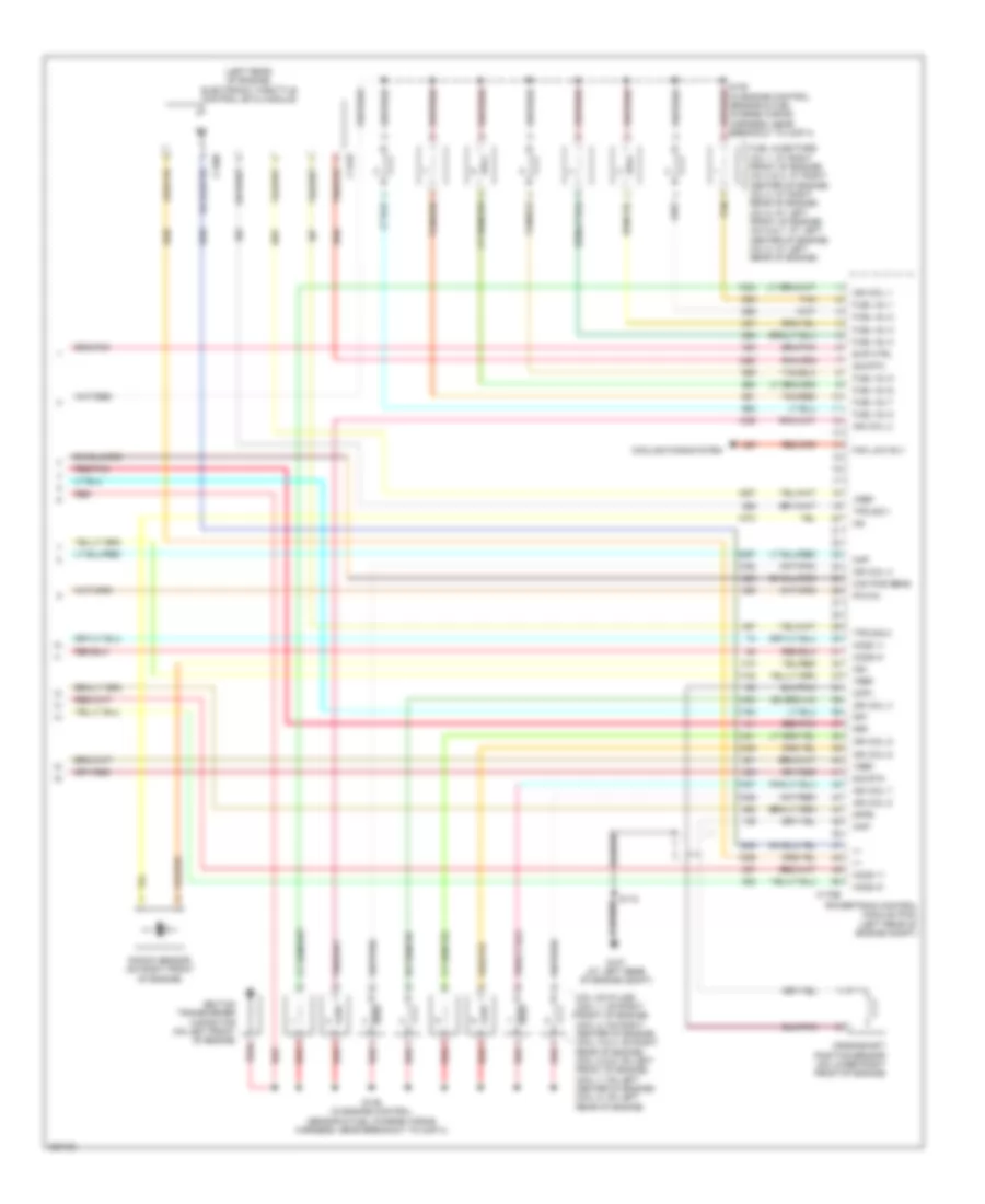
ENGINE PERFORMANCE
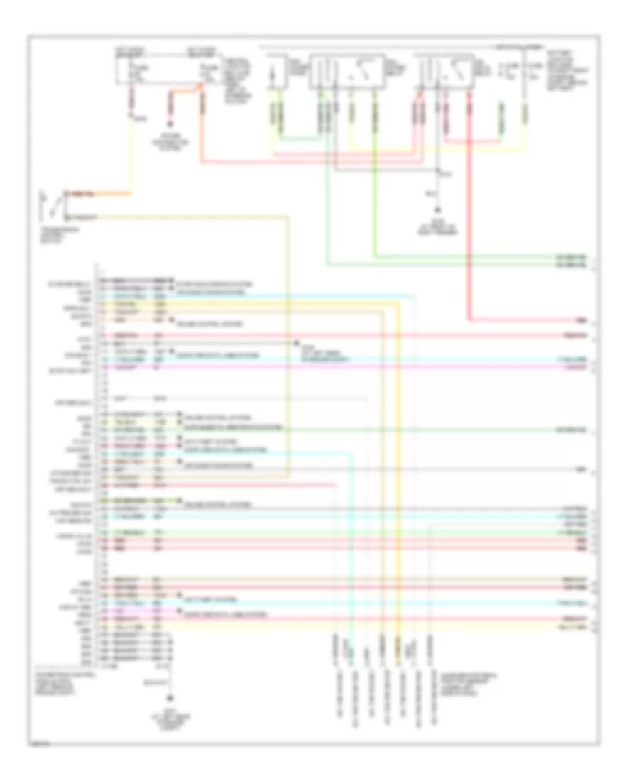
Engine Performance Wiring Diagram (1 of 5) for Ford Crown Victoria 2006
 https://portal-diagnostov.com/license.html
Automotive Electricians Portal FZCO
Automotive Electricians Portal FZCO
https://portal-diagnostov.com/license.html
https://portal-diagnostov.com/license.html
Automotive Electricians Portal FZCO
Automotive Electricians Portal FZCO
List of elements for Engine Performance Wiring Diagram (1 of 5) for Ford Crown Victoria 2006:
- A/c pre sen sig
- Acc ped pos sn 1
- Acc ped pos sn 2
- Acc ped pos sn 3
- Acc ped pos sn rtn
- Acc ped pos sn vref
- Accelerator pedal position sensor (under left side of dash)
- Accr
- Accs
- Air conditioning system
- Anti-theft system
- App sen sig 2
- App sen sig 3
- Apps sig 1
- Battery junction box (bjb) (in right front of engine compt, behind battery)
- Bps
- C175b
- Can bus +
- Can bus -
- Central junction box (cjb) (below dash, left of steering column)
- Computer data lines system
- Cruise control system
- Evap can vent
- Feps
- Fpc
- Fpm
- Ftpt
- Fuse 10a
- Fuse 15a
- Fuse 30a
- G106 (at left rear of engine compt)
- G107 (at left rear of engine compt)
- G109 (at front of right fender)
- Gnd
- Hot at all times
- Hot in run or start
- Ign coils relay
- Intake sen sig
- Maf sens sig
- Maf/iat sen
- Pcm power diode
- Pcm power relay
- Power distribution system
- Powertrain control module (pcm) (left rear of engine compt)
- Rdi
- Red
- Red/pnk
- Rtn sig
- Rx in
- S118
- S121
- S276
- Sccs
- Sig rtn
- Starter relay
- Starting/charging system
- Trans ctrl sw
- Transmission control switch
- Tx out
- Vapor valve
- Vbatt
- Vpwr
- Vref
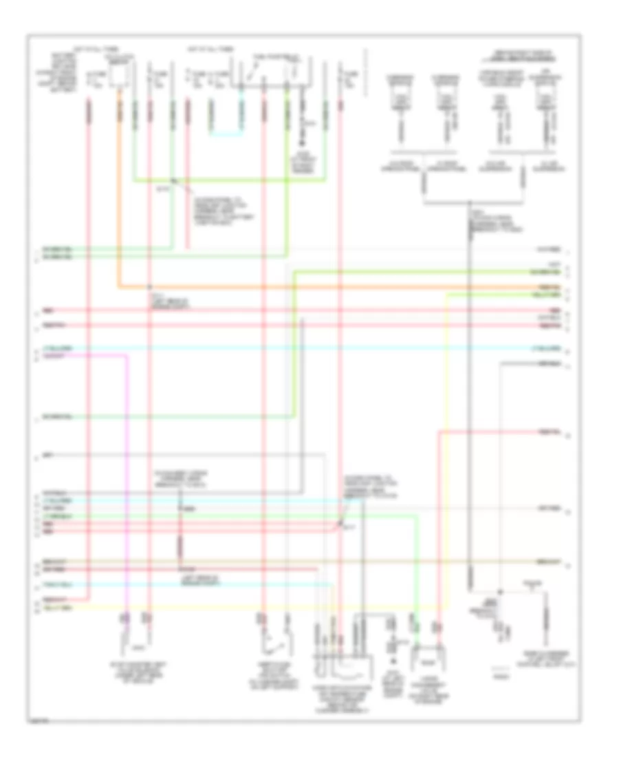
Engine Performance Wiring Diagram (2 of 5) for Ford Crown Victoria 2006
 https://portal-diagnostov.com/license.html
Automotive Electricians Portal FZCO
Automotive Electricians Portal FZCO
https://portal-diagnostov.com/license.html
https://portal-diagnostov.com/license.html
Automotive Electricians Portal FZCO
Automotive Electricians Portal FZCOList of elements for Engine Performance Wiring Diagram (2 of 5) for Ford Crown Victoria 2006:
- (behind right side of dash, above glove box)
- (in dash panel to headlamp junction
- (in dash panel to headlamp junction harness, near breakout to battery junction box)
- (in main body wiring harness, near breakout to g212)
- (left rear of engine compt)
- A/c clutch relay
- Air suspension module
- Battery junction box (bjb) (in right front of engine compt, behind battery)
- C2131a
- C2231b
- C290a
- C9013b
- Evap canister vent valve solenoid (under left rear of vehicle)
- Fuel pump relay
- Fuse 10a
- Fuse 15a
- Fuse 20a
- G107 (at left rear of engine compt)
- G109 (at front of right fender)
- Harness, near breakout to c1019)
- Hot at all times
- Inertia fuel shut-off (ifs) switch (in luggage compt, on left support)
- Mass air flow/intake air temperature (maf/iat) sensor (behind air cleaner assembly)
- Overhead console
- Police
- Radio
- Red
- Red/pnk
- S111 (left rear of engine compt)
- S117
- S118
- S119
- S121
- S130
- S231 (in main wiring harness, near breakout to g200)
- S247 (near breakout to c410)
- S256
- Vapor management valve (on right rear of engine)
- Variable assist power steering (vaps) module
- Vhcl spd input
- W/ air suspension
- W/ roof opening panel
- W/o air suspension
- W/o roof opening panel
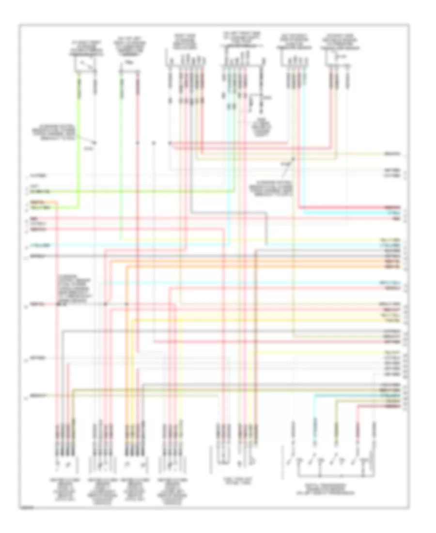
Engine Performance Wiring Diagram (3 of 5) for Ford Crown Victoria 2006
 https://portal-diagnostov.com/license.html
Automotive Electricians Portal FZCO
Automotive Electricians Portal FZCO
https://portal-diagnostov.com/license.html
https://portal-diagnostov.com/license.html
Automotive Electricians Portal FZCO
Automotive Electricians Portal FZCOList of elements for Engine Performance Wiring Diagram (3 of 5) for Ford Crown Victoria 2006:
- (at right front of engine) power steering pressure switch
- (in engine control sensor & fuel charge wiring harness, near breakout to cop 4)
- (in engine control sensor & fuel charge wiring harness, near breakout to pcm)
- (in engine control sensor & fuel charge wiring harness, near breakout to turbine shaft speed sensor) s146
- (on left front side of luggage compt) fuel pump driver module
- (on right side center of engine) a/c pressure transducer sensor
- (on top left front of engine) cylinder-head temperature sensor
- (on top right side of engine) injector pressure sensor
- (right side of engine) egr system module (esm)
- Digital transmission range (dtr) sensor (on left side of transmission)
- Dpfe
- Evp
- Fp feed
- Frp
- Frt
- Fuel tank unit (in fuel tank)
- G406 (at rear center of luggage compt)
- Heated oxygen sensor (ho2s) 11 (lower right rear of engine, in exhaust manifold)
- Heated oxygen sensor (ho2s) 12 (in exhaust, rear of catalyst)
- Heated oxygen sensor (ho2s) 21 (lower left rear of engine, in exhaust manifold)
- Heated oxygen sensor (ho2s) 22 (in exhaust, rear of catalyst)
- Map
- Nca
- Red
- Red/pnk
- S123
- S126
- S405
- Sig
- Tr1
- Tr2
- Tr3a
- Tr4
- Vpwr
- Vref
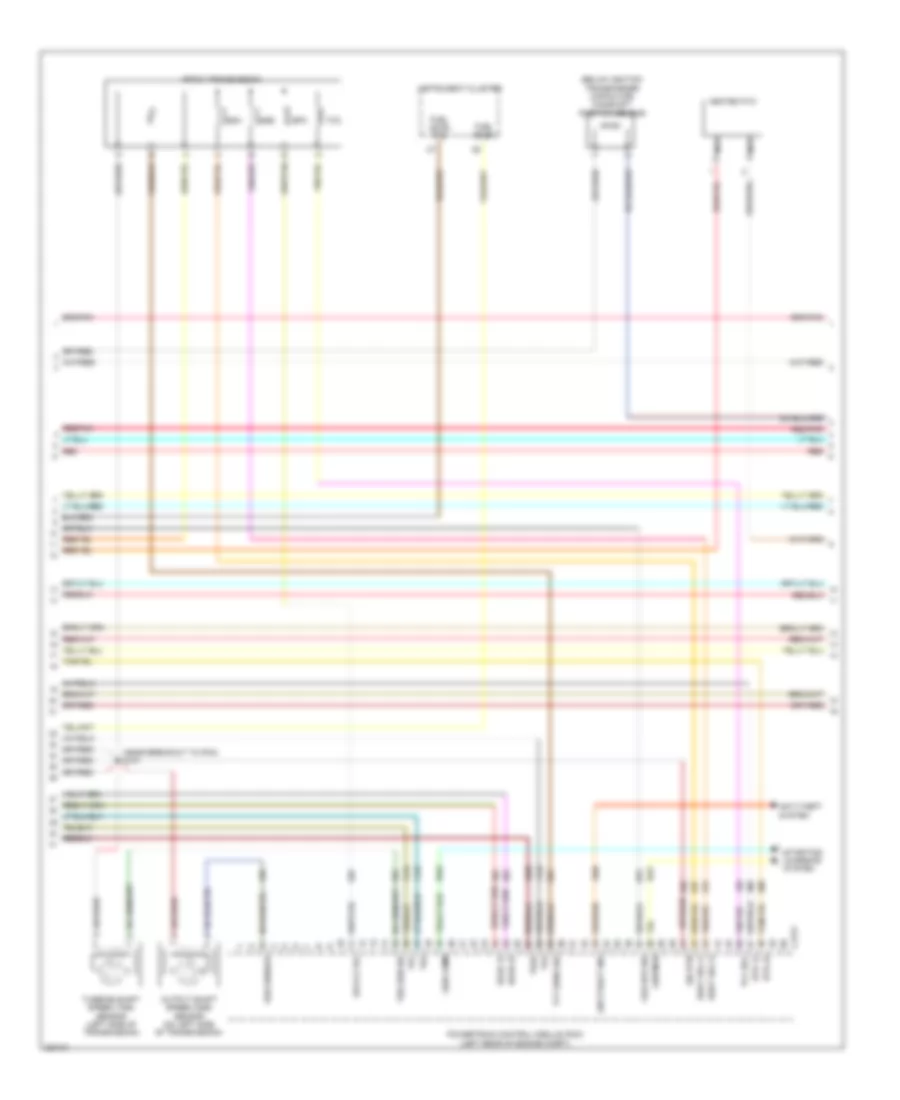
Engine Performance Wiring Diagram (4 of 5) for Ford Crown Victoria 2006
 https://portal-diagnostov.com/license.html
Automotive Electricians Portal FZCO
Automotive Electricians Portal FZCO
https://portal-diagnostov.com/license.html
https://portal-diagnostov.com/license.html
Automotive Electricians Portal FZCO
Automotive Electricians Portal FZCOList of elements for Engine Performance Wiring Diagram (4 of 5) for Ford Crown Victoria 2006:
- (below ignition transformer capacitor) camshaft position sensor
- (near breakout to pcm) s147
- 4r70w transmission
- Anti-theft ind
- Anti-theft system
- C175t
- Epc
- Epcs ctrl
- Fuel level
- Fuel level rtn
- Gen comm
- Gen mon
- Heated pvc
- Ho2s 12
- Ho2s 22
- Htr 12
- Htr 22
- Instrument cluster
- Nca
- Oss sensor
- Output shaft speed (oss) sensor (on left side of transmission)
- Powertrain control module (pcm) (left rear of engine compt)
- Red
- Shift sol a
- Shift sol b
- Sig rtn
- Ssa
- Ssb
- Starting/ charging system
- Tcc
- Tcc sol
- Tft sens sig
- Tr1
- Tr2
- Tr3a
- Tr4
- Tss sen sig
- Turbine shaft speed (tss) sensor (left side of transmission)
- Veh spd sig
Engine Performance Wiring Diagram (5 of 5) for Ford Crown Victoria 2006
 https://portal-diagnostov.com/license.html
Automotive Electricians Portal FZCO
Automotive Electricians Portal FZCO
https://portal-diagnostov.com/license.html
https://portal-diagnostov.com/license.html
Automotive Electricians Portal FZCO
Automotive Electricians Portal FZCOList of elements for Engine Performance Wiring Diagram (5 of 5) for Ford Crown Victoria 2006:
- (left rear of engine) electronic throttle control (etc) module
- +/-
- C1368
- C1449
- C175e
- Cam pos sens
- Ckp+
- Ckp-
- Coil on plugs (coil 1: on right front of engine) (coil 2: on right center of engine) (coil 3 & 4: on right rear of engine) (coil 5 & 6: on left front of engine) (coil 7: on left center of engine) (coil 8: on left rear of engine)
- Cooling fans system
- Crankshaft position sensor (on lower right front of engine)
- Dpfe
- Evr ctrl
- Fan low rly
- Frp
- Frt
- Fuel inj 1
- Fuel inj 2
- Fuel inj 3
- Fuel inj 4
- Fuel inj 5
- Fuel inj 6
- Fuel inj 7
- Fuel inj 8
- Fuel injectors (inj 1: at right front of engine) (inj 2 & 3: at right center of engine) (inj 4: at right rear of engine) (inj 5: at left front of engine) (inj 6 & 7: at left center of engine) (inj 8: at left rear of engine)
- G107 (at left rear of engine compt)
- Ho2s 11
- Ho2s 21
- Ign coil 1
- Ign coil 2
- Ign coil 3
- Ign coil 4
- Ign coil 5
- Ign coil 6
- Ign coil 7
- Ign coil 8
- Ignition transformer capacitor (on left front of engine)
- Knock sensor (on right front of engine)
- Ks+
- Ks-
- Map
- Pcvhc
- Powertrain control module (pcm) (left rear of engine compt)
- Red
- Red/pnk
- S118
- S136 (in engine control sensor & fuel charge wiring harness, near breakout to cop 4)
- Sig rtn
- Tan
- Tan/red
- Tps sig 1
- Tps sig 2
- Vref

 Čeština
 Dansk
Dansk Deutsch
 Ελληνικά
 English
 English
 Español
 Suomi
Suomi Français
 Français
 עברית
עברית Hrvatski
 Magyar
 Italiano
 한국어
한국어 Nederlands
 Polski
 Português
 Português
 Română
 Русский
 Slovenčina
 Slovenščina
 Svenska
 Türkçe
 中文 (中国)
