ENGINE PERFORMANCE
5.4L
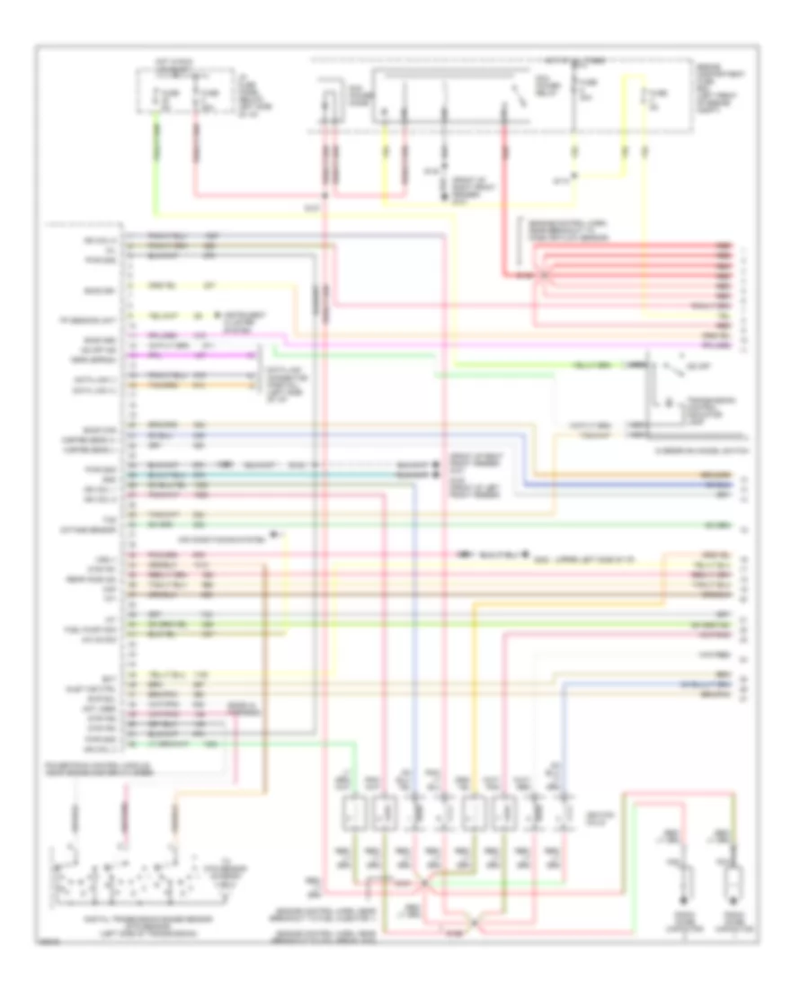
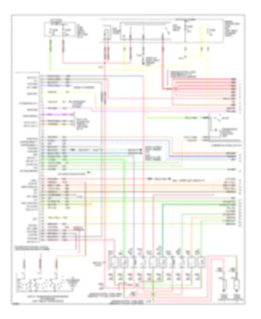
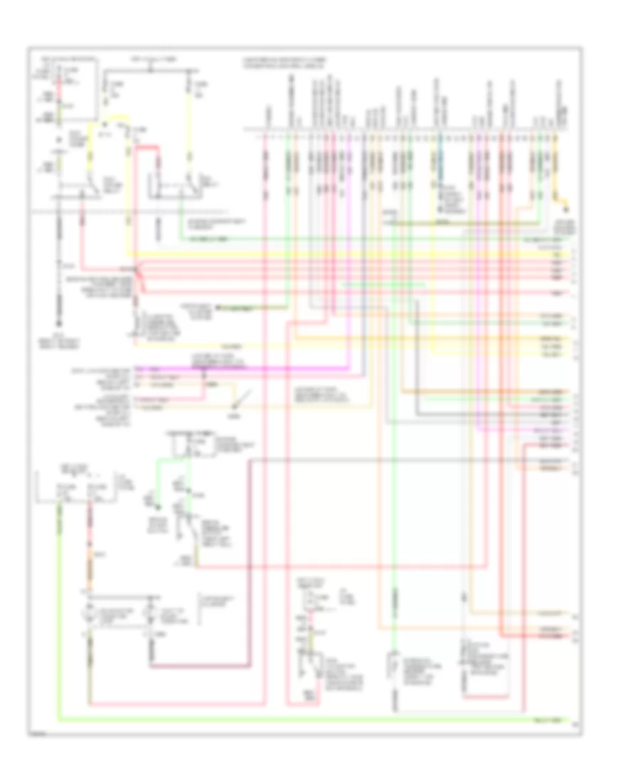
5.4L, Engine Performance Wiring Diagrams (1 of 4) for Ford Cutaway E350 1997
 https://portal-diagnostov.com/license.html
Automotive Electricians Portal FZCO
Automotive Electricians Portal FZCO
https://portal-diagnostov.com/license.html
https://portal-diagnostov.com/license.html
Automotive Electricians Portal FZCO
Automotive Electricians Portal FZCO
List of elements for 5.4L, Engine Performance Wiring Diagrams (1 of 4) for Ford Cutaway E350 1997:
- (ends in harness)
- (engine control harn, near breakout to coil per plug 6)
- (engine control harn, near breakout to fuel injector 1)
- (engine control harn, near breakout to mass air flow sensor)
- (front of right front fender) g101
- (upper left side of i/p)
- A/c on sig
- Air conditioning system
- Data link (+)
- Data link (-)
- Data link connector (partial) (left side of i/p)
- Digital transmission range sensor (dtr sensor) (left side of transmission)
- Dtr-tr1
- Dtr-tr2
- Dtr-tr4
- E4od ccs
- E4od ss1
- E4od ss2
- Ect
- Engine compartment fuse box (left front of engine compt)
- Evr sol
- Feps (eprom)
- Fp sending unit
- Fuel pump mon
- Fuse 30a
- Fuse 5a
- G100 (front of left front fender)
- G202
- Gnd
- Hot at all times
- Hot in run or start
- I/p fuse panel (below left side of i/p)
- Iat
- Ign coil 1
- Ign coil 3
- Ign coil 5
- Ign coil 6
- Ignition coils
- Inlet air ctrl
- Instrument cluster system
- Maf
- Mil
- Misfire sens (+)
- Misfire sens (-)
- Nca
- Not used
- O/d off
- Octane sensor
- Od off ind
- Overdrive cancel switch
- Pcm power diode
- Pcm power relay
- Powertrain control module (near brake master cylinder)
- Pwr gnd
- R n
- Radio noise capacitor
- Rear ho2s (22)
- Red
- S110
- S127
- S140
- S142
- S156
- S161
- S169
- S205
- Tcs
- Tft
- To dtr sensor (diagram 4 of 4)
- Transmission control indicator lamp
- Vss (-)
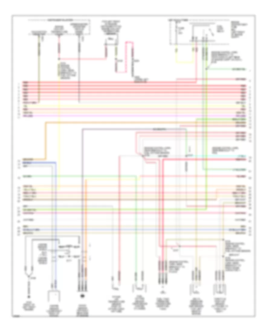
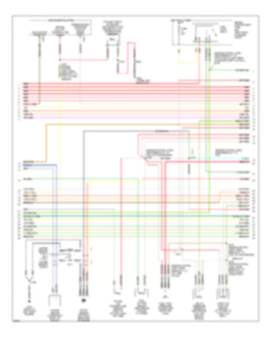
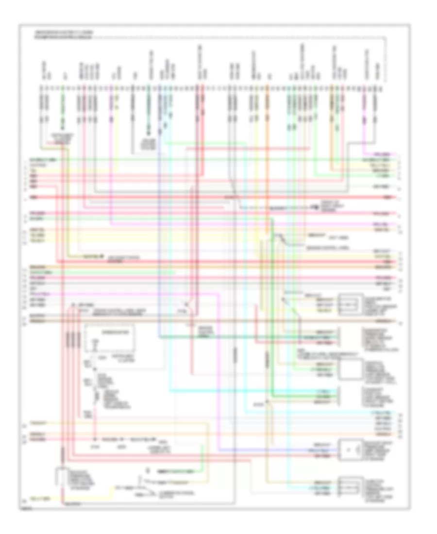
5.4L, Engine Performance Wiring Diagrams (2 of 4) for Ford Cutaway E350 1997
 https://portal-diagnostov.com/license.html
Automotive Electricians Portal FZCO
Automotive Electricians Portal FZCO
https://portal-diagnostov.com/license.html
https://portal-diagnostov.com/license.html
Automotive Electricians Portal FZCO
Automotive Electricians Portal FZCOList of elements for 5.4L, Engine Performance Wiring Diagrams (2 of 4) for Ford Cutaway E350 1997:
- (engine control harn, near breakout to 76-pin conn in left rear of engine compt on cowl) s126
- (engine control harn, near breakout to coil per plug 9)
- (engine control harn, near breakout to fuel octane sensor) s136
- (engine control harn, near breakout to pcm)
- (speedometer/ odometer) vehicle speed input
- (top left front of engine) instrumentation engine coolant temperature sensor
- C224
- C225
- Delta pressure feedback egr sensor (top left rear of engine)
- Engine compartment fuse box (left front of engine compt)
- Engine coolant temperature gauge
- Fuel octane sensor (near brake master cylinder)
- Fuel pump relay
- Fuel tank pressure transducer (near fuel tank)
- Fuse 30a
- G100 (front of left front fender)
- G202 (upper left side of i/p)
- Hot at all times
- Instrument cluster
- Intake air temperature sensor (part of intake clean air tube)
- Knock sensor (top right rear side of engine)
- Malfunction indicator
- Misfire sensor (lower right front of engine)
- Misfire sensor shield
- Nca
- Red
- Red/pnk
- S137
- S138 (engine control harn, near breakout to fuel octane sensor)
- S157
- S158 (engine control harn, near breakout to radio noise capacitor 1)
- S169
- S170
- S171
- S205
- Throttle position sensor (attached to throttle body)
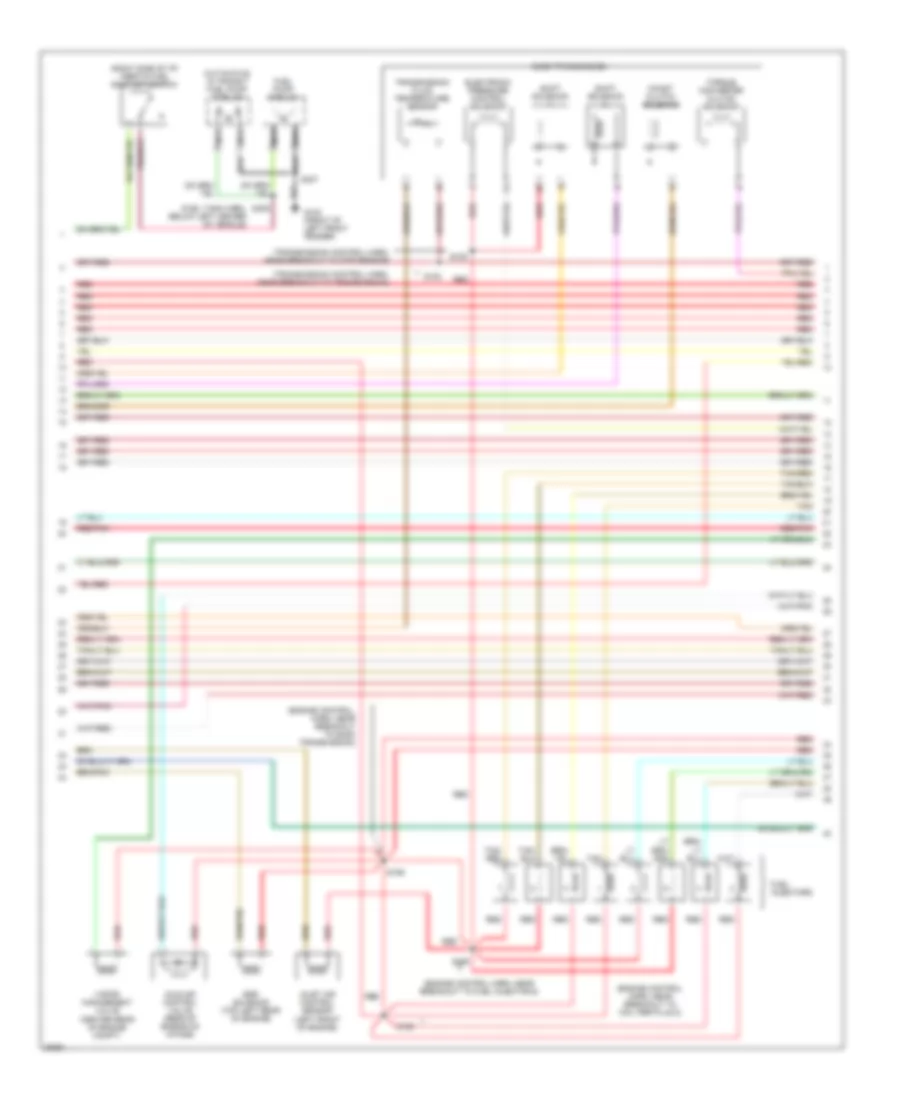
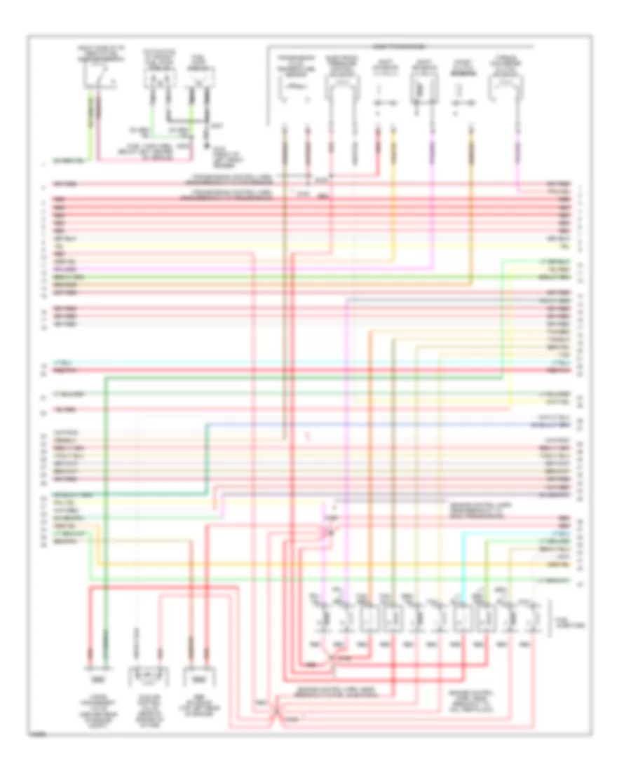
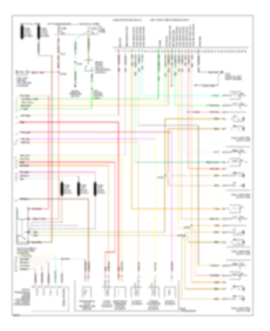
5.4L, Engine Performance Wiring Diagrams (3 of 4) for Ford Cutaway E350 1997
 https://portal-diagnostov.com/license.html
Automotive Electricians Portal FZCO
Automotive Electricians Portal FZCO
https://portal-diagnostov.com/license.html
https://portal-diagnostov.com/license.html
Automotive Electricians Portal FZCO
Automotive Electricians Portal FZCOList of elements for 5.4L, Engine Performance Wiring Diagrams (3 of 4) for Ford Cutaway E350 1997:
- (center rear of engine compt)
- (cutaways) in transit fuel pump module
- (engine control harn, near breakout to coil per plug 2)
- (engine control harn, near breakout to fuel injector 6)
- (engine control, harn, near breakout to e4od transmission)
- (fuel tank harn, below left center of vehicle)
- (left front of engine)
- (right side of i/p) inertia fuel shut-off switch
- (transmission control harn, near breakout to dtr sensor)
- (transmission control harn, near breakout to transmission)
- Coast clutch solenoid
- E4od transmission
- Egr solenoid (top left rear of engine)
- Electronic pressure control solenoid
- Fuel injectors
- Fuel pump module
- G100 (front of left front fender)
- Idle air control valve (rear of engine on intake)
- Inlet air control sensor
- Nca
- Red
- Red/pnk
- S100
- S102
- S155
- S159
- S160
- S307
- S309
- Shift solenoid
- Tan
- Tan/ red
- Tan/red
- Torque converter clutch solenoid
- Transmission fluid temperature sensor
- Vapor management valve
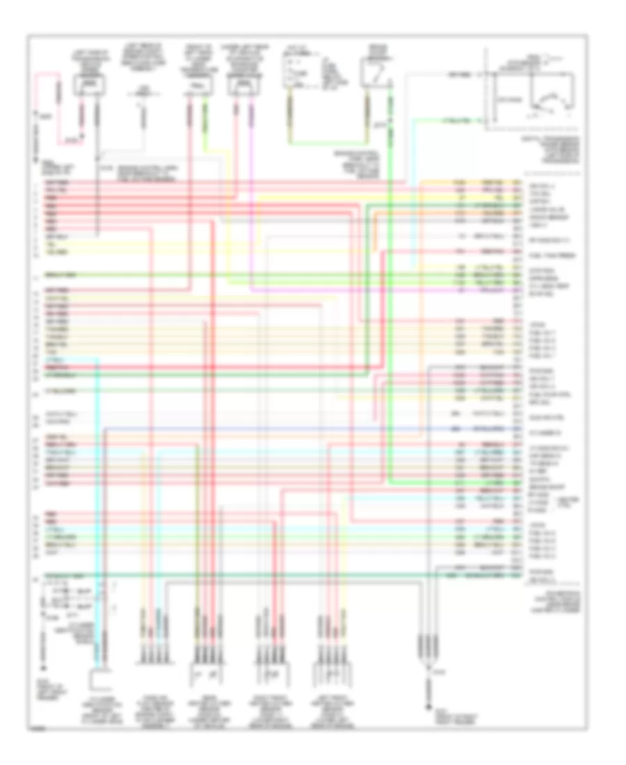
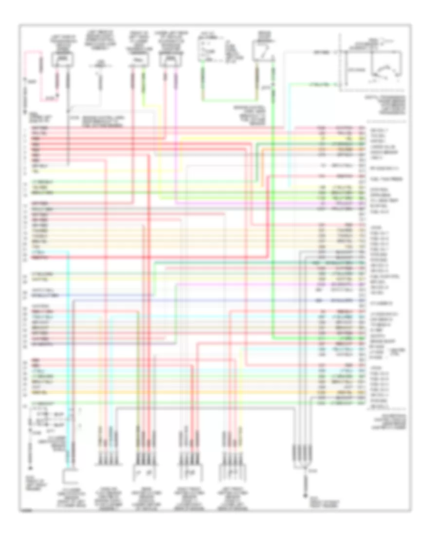
5.4L, Engine Performance Wiring Diagrams (4 of 4) for Ford Cutaway E350 1997
 https://portal-diagnostov.com/license.html
Automotive Electricians Portal FZCO
Automotive Electricians Portal FZCO
https://portal-diagnostov.com/license.html
https://portal-diagnostov.com/license.html
Automotive Electricians Portal FZCO
Automotive Electricians Portal FZCOList of elements for 5.4L, Engine Performance Wiring Diagrams (4 of 4) for Ford Cutaway E350 1997:
- (engine control harn, near breakout to fuel octane sensor)
- (front of left head) cylinder head temperature sensor
- (left rear of engine compt) speed control servo/amplifier assembly
- (left side of transmission) vehicle speed sensor
- (under left rear of vehicle) evaporative emissions canister purge valve
- 270 ohms
- 5v ref
- Brake on/off
- Brake on/off switch
- Cyl head temp
- Cylinder id
- Cylinder identification sensor (front of left cylinder head)
- Cylinder identification sensor shield
- Digital transmission range sensor (dtr sensor) (left side of transmission)
- Dpfe sens
- Dtr-tr3a
- Epc sol
- Evap sol
- From dtr sensor (diagram 1 of 4)
- Fuel inj 1
- Fuel inj 2
- Fuel inj 3
- Fuel inj 4
- Fuel inj 5
- Fuel inj 6
- Fuel inj 7
- Fuel inj 8
- Fuel pump ctrl
- Fuel tank press
- Fuse 15a
- G100 (front of left front fender)
- G101 (front of right front fender)
- G202 (upper left side of i/p)
- Heater ctrl
- Hot at all times
- I/p fuse panel (below left side of i/p)
- Idle air ctrl
- Ign coil 2
- Ign coil 4
- Ign coil 7
- Ign coil 8
- Kap b(+)
- Knock sensor
- Left front heated oxygen sensor (ho2s 21) (lower left rear of engine)
- Lf ho2s
- Lf ho2s sig (21)
- Maf sens in
- Mass air flow sensor (center of engine compt, in air cleaner assembly)
- Nca
- Powertrain control module (near brake master cylinder)
- Pwr gnd
- R ho2s
- Rear heated oxygen sensor (ho2s 22) (under center of vehicle)
- Red
- Red/pnk
- Rf ho2s
- Rf ho2s sig (11)
- Right front heated oxygen sensor (ho2s 11) (lower right rear of engine)
- S135
- S139
- S140
- S169
- S170
- S171
- S205
- Sig rtn
- Tan
- Tan/red
- Tcc sol
- Tp sens in
- Vapor valve
- Vpwr
- Vss (+)
- Vss input
6.8L
6.8L, Engine Performance Wiring Diagrams (1 of 4) for Ford Cutaway E350 1997
 https://portal-diagnostov.com/license.html
Automotive Electricians Portal FZCO
Automotive Electricians Portal FZCO
https://portal-diagnostov.com/license.html
https://portal-diagnostov.com/license.html
Automotive Electricians Portal FZCO
Automotive Electricians Portal FZCOList of elements for 6.8L, Engine Performance Wiring Diagrams (1 of 4) for Ford Cutaway E350 1997:
- (ends in harness)
- (engine control harn, near breakout to fuel injector 1)
- (engine control harn, near breakout to fuel injector 6)
- (engine control harn, near breakout to mass air flow sensor)
- (front of right front fender) g101
- (upper left side of i/p)
- A/c on sig
- Air conditioning system
- C116
- Data link (+)
- Data link (-)
- Data link connector (partial) (left side of i/p)
- Digital transmission range sensor (dtr sensor) (left side of transmission)
- Dtr-tr1
- Dtr-tr2a
- Dtr-tr4
- E4od ccs
- E4od ss1
- E4od ss2
- Ect
- Engine compartment fuse box (left front of engine compt)
- Evr sol
- Feps (eprom)
- Fp sending unit
- Fuel inj 10
- Fuel pump mon
- Fuse 30a
- Fuse 5a
- G100 (front of left front fender)
- G202
- Gnd
- Hot at all times
- Hot in run or start
- I/p fuse panel (below left side of i/p)
- Iat
- Ign coil 1
- Ign coil 10
- Ign coil 5
- Ign coil 6
- Ignition coils
- Instrument cluster system
- Maf
- Mil
- Misfire sens (+)
- Misfire sens (-)
- Nca
- Not used
- O/d off
- Octane sensor
- Od off ind
- Overdrive cancel switch
- Pcm power diode
- Pcm power relay
- Powertrain control module (near brake master cylinder)
- Pwr gnd
- R n
- Radio noise capacitor
- Rear ho2s (22)
- Red
- S110
- S127
- S140
- S142
- S161
- S162
- S169
- S205
- Tcs
- Tft
- To dtr sensor (diagram 4 of 4)
- Transmission control indicator lamp
- Vss (-)
6.8L, Engine Performance Wiring Diagrams (2 of 4) for Ford Cutaway E350 1997
 https://portal-diagnostov.com/license.html
Automotive Electricians Portal FZCO
Automotive Electricians Portal FZCO
https://portal-diagnostov.com/license.html
https://portal-diagnostov.com/license.html
Automotive Electricians Portal FZCO
Automotive Electricians Portal FZCOList of elements for 6.8L, Engine Performance Wiring Diagrams (2 of 4) for Ford Cutaway E350 1997:
- (engine control harn, near breakout to 76-pin conn in left rear of engine compt on cowl) s126
- (engine control harn, near breakout to coil per plug 9)
- (engine control harn, near breakout to fuel octane sensor) s136
- (engine control harn, near breakout to pcm)
- (speedometer/ odometer) vehicle speed input
- (top left front of engine) instrumentation engine coolant temperature sensor
- C224
- C225
- Delta pressure feedback egr sensor (top left rear of engine)
- Engine compartment fuse box (left front of engine compt)
- Engine coolant temperature gauge
- Fuel octane sensor (near brake master cylinder)
- Fuel pump relay
- Fuel tank pressure transducer (near fuel tank)
- Fuse 30a
- G100 (front of left front fender)
- G202 (upper left side of i/p)
- Hot at all times
- Instrument cluster
- Intake air temperature sensor (part of intake clean air tube)
- Knock sensor (top right rear side of engine)
- Malfunction indicator
- Misfire sensor (lower right front of engine)
- Misfire sensor shield
- Nca
- Red
- Red/pnk
- S137
- S138 (engine control harn, near breakout to fuel octane sensor)
- S157
- S158 (engine control harn, near breakout to radio noise capacitor 1)
- S169
- S170
- S171
- S205
- Throttle position sensor (attached to throttle body)
6.8L, Engine Performance Wiring Diagrams (3 of 4) for Ford Cutaway E350 1997
 https://portal-diagnostov.com/license.html
Automotive Electricians Portal FZCO
Automotive Electricians Portal FZCO
https://portal-diagnostov.com/license.html
https://portal-diagnostov.com/license.html
Automotive Electricians Portal FZCO
Automotive Electricians Portal FZCOList of elements for 6.8L, Engine Performance Wiring Diagrams (3 of 4) for Ford Cutaway E350 1997:
- (center rear of engine compt)
- (cutaways) in transit fuel pump module
- (engine control harn, near breakout to coil per plug 2)
- (engine control harn, near breakout to e4od transmission)
- (engine control harn, near breakout to fuel injector 6)
- (fuel tank harn, below left center of vehicle)
- (right side of i/p) inertia fuel shut-off switch
- (transmission control harn, near breakout to dtr sensor)
- (transmission control harn, near breakout to transmission)
- Coast clutch solenoid
- E4od transmission
- Egr solenoid (top left rear of engine)
- Electronic pressure control solenoid
- Fuel injectors
- Fuel pump module
- G100 (front of left front fender)
- Idle air control valve (rear of engine on intake)
- Nca
- Red
- Red/pnk
- S100
- S102
- S155
- S159
- S160
- S307
- S309
- Shift solenoid
- Tan
- Tan/ red
- Tan/red
- Torque converter clutch solenoid
- Transmission fluid temperature sensor
- Vapor management valve
6.8L, Engine Performance Wiring Diagrams (4 of 4) for Ford Cutaway E350 1997
 https://portal-diagnostov.com/license.html
Automotive Electricians Portal FZCO
Automotive Electricians Portal FZCO
https://portal-diagnostov.com/license.html
https://portal-diagnostov.com/license.html
Automotive Electricians Portal FZCO
Automotive Electricians Portal FZCOList of elements for 6.8L, Engine Performance Wiring Diagrams (4 of 4) for Ford Cutaway E350 1997:
- (engine control harn, near breakout to fuel octane sensor)
- (front of left head) cylinder head temperature sensor
- (left rear of engine compt) speed control servo/amplifier assembly
- (left side of transmission) vehicle speed sensor
- (under left rear of vehicle) evaporative emissions canister purge valve
- 270 ohms
- 5v ref
- Brake on/off
- Brake on/off switch
- Cyl head temp
- Cylinder id
- Cylinder identification sensor (front of left cylinder head)
- Cylinder identification sensor shield
- Digital transmission range sensor (dtr sensor) (left side of transmission)
- Dpfe sens
- Dtr-tr3a
- Epc sol
- Evap sol
- From dtr sensor (diagram 1 of 4)
- Fuel inj 1
- Fuel inj 2
- Fuel inj 3
- Fuel inj 4
- Fuel inj 5
- Fuel inj 6
- Fuel inj 7
- Fuel inj 8
- Fuel inj 9
- Fuel pump ctrl
- Fuel tank press
- Fuse 15a
- G100 (front of left front fender)
- G101 (front of right front fender)
- G202 (upper left side of i/p)
- Heater ctrl
- Hot at all times
- I/p fuse panel (below left side of i/p)
- Iac sol
- Ign coil 2
- Ign coil 3
- Ign coil 4
- Ign coil 7
- Ign coil 8
- Ign coil 9
- Kap b(+)
- Knock sensor
- Left front heated oxygen sensor (ho2s 21) (lower left rear of engine)
- Lf ho2s
- Lf ho2s sig (21)
- Maf sens in
- Mass air flow sensor (center of engine compt, in air cleaner assembly)
- Nca
- Powertrain control module (near brake master cylinder)
- Pwr gnd
- R ho2s
- Rear heated oxygen sensor (ho2s 22) (under center of vehicle)
- Red
- Red/pnk
- Rf ho2s
- Rf ho2s sig (11)
- Right front heated oxygen sensor (ho2s 11) (lower right rear of engine)
- S135
- S139
- S140
- S169
- S170
- S171
- S205
- Sig rtn
- Tan
- Tan/red
- Tcc sol
- Tp sens in
- Vapor valve
- Vpwr
- Vss (+)
- Vss input
7.3L
7.3L DI Turbo Diesel, Engine Performance Wiring Diagrams (1 of 3) for Ford Cutaway E350 1997
 https://portal-diagnostov.com/license.html
Automotive Electricians Portal FZCO
Automotive Electricians Portal FZCO
https://portal-diagnostov.com/license.html
https://portal-diagnostov.com/license.html
Automotive Electricians Portal FZCO
Automotive Electricians Portal FZCOList of elements for 7.3L DI Turbo Diesel, Engine Performance Wiring Diagrams (1 of 3) for Ford Cutaway E350 1997:
- "wait to start" indicator
- (ends in harn)
- (engine control sensor harness, near breakout to mass air flow sensor)
- (front of left front fender)
- (lower i/p harn, near breakout to rke data link conn)
- (near brake master cylinder)
- App ref volt rtn
- Aux tach feed
- Auxiliary powertrain control connector (partial) (behind left side of i/p)
- Brake on/off switch
- Brake press sw
- Brake pressure switch (near left front rail)
- Brake warning ind
- Bus (+)
- Bus (-)
- C225
- Cam pos sens
- Ccs
- Cruise control system
- Data link connector (partial) (below left side of i/p)
- Dlc
- Dtr-tr1
- Ebp
- Engine compartment fuse box
- Engine oil temperature sensor (front top of engine)
- Eot
- Fuse 15a
- Fuse 30a
- Fuse 5a
- G100
- G101 (front of right front fender)
- Glow plug relay
- Horn/speed ctrl sw gnd
- Hot at all times
- Hot in run or start
- I/p fuse panel
- Iat
- Idle validation sw
- Idle validation switch (open at idle) (near accele- rator pedal)
- Idm relay
- Injection pressure regulator (top center of engine)
- Instrument cluster
- Instrument cluster system
- Intake air temperature sensor (top center of engine)
- Malfunction indicator lamp
- Pcm dlc
- Pcm power diode
- Pcm power relay
- Powertrain control module
- Red
- S110
- S127
- S129
- S140
- S142
- S167
- S213
- S262
- S263
- Shield gnd
- Ss1
- Tcil
- Tcs
- Tft
- Vss gnd
7.3L DI Turbo Diesel, Engine Performance Wiring Diagrams (2 of 3) for Ford Cutaway E350 1997
 https://portal-diagnostov.com/license.html
Automotive Electricians Portal FZCO
Automotive Electricians Portal FZCO
https://portal-diagnostov.com/license.html
https://portal-diagnostov.com/license.html
Automotive Electricians Portal FZCO
Automotive Electricians Portal FZCOList of elements for 7.3L DI Turbo Diesel, Engine Performance Wiring Diagrams (2 of 3) for Ford Cutaway E350 1997:
- (engine control harn)
- (front of right front fender)
- (near brake master cylinder)
- (not used)
- (trans control harn, near breakout to dtr sensor)
- (upper left side of i/p)
- A/c on sig
- Accelerator pedal position sensor (under left side of i/p)
- Accl pdl pos sens
- Air conditioning system
- Baro
- Barometric pressure (baro) sensor (below i/p, at base of steering column)
- Boo
- C224
- Camshaft position (cmp) sensor (front center of engine)
- Cid sig
- Cmp rtn
- Cruise control system
- Dtr-tr2
- Dtr-tr4
- Ect
- Epc
- Epr
- Exhaust back pressure (ebp) sensor (right side of engine)
- Exhaust pressure regulator (top center of engine)
- Fuel delivery sig
- G101
- G202
- Glow plug ctrl
- Icp
- Idm enable out
- Idm sig in
- Injection control pressure (icp) sensor (top left side of engine)
- Instrument cluster
- Instrument cluster system
- Ipr
- Kapwr
- Manifold absolute pressure (map) sensor (top right side of safety wall)
- Map
- Nca
- Overdrive cancel switch
- Powertrain control module
- Pwr gnd
- Red
- S1001
- S1002
- S135 (engine control harn)
- S136
- S138
- S139
- S140
- S205
- S261 (lower i/p harn, near breakout to rke data link conn)
- Sig rtn
- Speed ctrl sig
- Speedometer
- Tcc
- Tcil
- Tcs
- Tr sensor
- Vehicle speed sensor (left side of transmission)
- Vpwr
- Vref
- Vss
- Vss in
- Wait to start ind
7.3L DI Turbo Diesel, Engine Performance Wiring Diagrams (3 of 3) for Ford Cutaway E350 1997
 https://portal-diagnostov.com/license.html
Automotive Electricians Portal FZCO
Automotive Electricians Portal FZCO
https://portal-diagnostov.com/license.html
https://portal-diagnostov.com/license.html
Automotive Electricians Portal FZCO
Automotive Electricians Portal FZCOList of elements for 7.3L DI Turbo Diesel, Engine Performance Wiring Diagrams (3 of 3) for Ford Cutaway E350 1997:
- #1 shift solenoid
- #2 shift solenoid
- (left front side of engine compt)
- Brake on/off switch (brake pedal support)
- Brake pressure switch
- Cid sig in
- Coast clutch solenoid
- Digital transmission range sensor (dtr sensor) (left side of transmission)
- E4od transmission
- Electronic pressure control solenoid
- Fuel delivery sig
- Fuel inj feed left
- Fuel inj feed right
- Fuel injector #1
- Fuel injector #2
- Fuel injector #3
- Fuel injector #4
- Fuel injector #5
- Fuel injector #6
- Fuel injector #7
- Fuel injector #8
- Fuel injectors/ glow plugs
- Fuel line heater (top center of engine)
- Fuse 15a
- Fuse 30a
- G100 (front of left front fender)
- Glow plug relay (top right side of engine)
- Hot at all times
- Hot in run or start
- I/p fuse panel
- Idm feedback sig
- Inj shield gnd
- Injector driver module
- Nca
- P, 2, 1
- P, n, 1
- P, r, 2
- P, r, n
- Pwr gnd
- Red
- S1000
- S1003
- S1004
- S1005
- S1006
- S1007
- S127
- S129
- S134 (engine control harn)
- Sig rtn
- Signal return
- Tan
- Tan/red
- Torque converter clutch solenoid
- Transmission fluid temperature sensor
- Vpwr

 Čeština
 Dansk
Dansk Deutsch
 Ελληνικά
 English
 English
 Español
 Suomi
Suomi Français
 Français
 עברית
עברית Hrvatski
 Magyar
 Italiano
 한국어
한국어 Nederlands
 Polski
 Português
 Português
 Română
 Русский
 Slovenčina
 Slovenščina
 Svenska
 Türkçe
 中文 (中国)
