ENGINE PERFORMANCE
5.4L
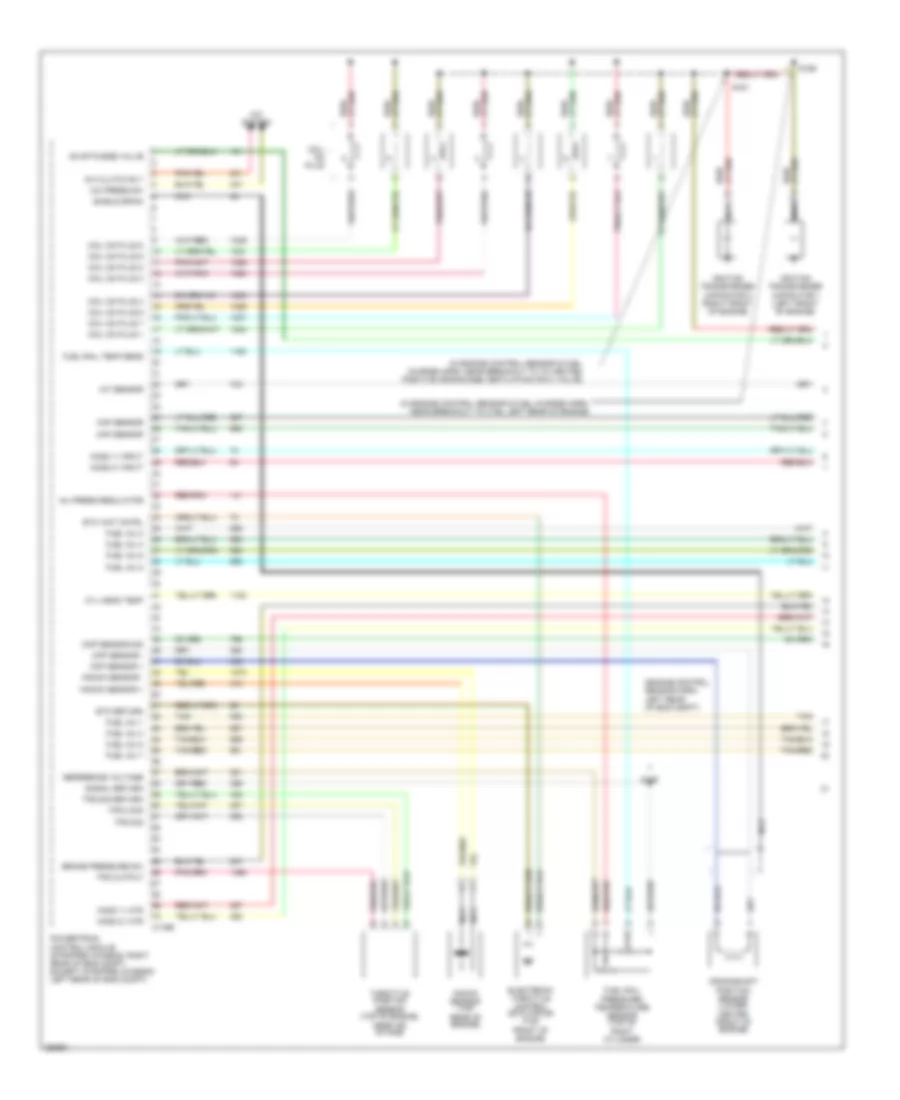
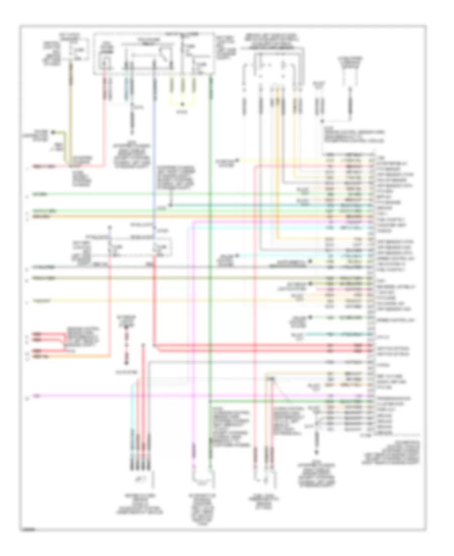
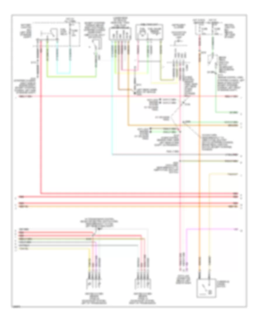
5.4L, Engine Performance Wiring Diagram, with Torqshift (1 of 5) for Ford E450 Super Duty 2007
 https://portal-diagnostov.com/license.html
Automotive Electricians Portal FZCO
Automotive Electricians Portal FZCO
https://portal-diagnostov.com/license.html
https://portal-diagnostov.com/license.html
Automotive Electricians Portal FZCO
Automotive Electricians Portal FZCO
List of elements for 5.4L, Engine Performance Wiring Diagram, with Torqshift (1 of 5) for Ford E450 Super Duty 2007:
- (engine control sensor harn, left rear of eng compt)
- (in engine control sensor & fuel charge harn, near breakout to c192, left rear of engine)
- (in engine control sensor & fuel charge harn, near breakout to to heated positive crankcase ventilation (pcv) valve)
- A/c clutch rly
- A/c press sw
- A/c system
- Brake pressure sw
- C175e
- Ckp sensor +
- Ckp sensor -
- Cmp sensor sig
- Coil on plug
- Coil on plug 1
- Coil on plug 2
- Coil on plug 3
- Coil on plug 4
- Coil on plug 5
- Coil on plug 6
- Coil on plug 7
- Coil on plug 8
- Crankshaft position sensor (lower center front of engine)
- Cyl head temp
- Electronic throttle control (etc) motor (top front of engine)
- Etc return
- Etc wot cntrl
- Evap purge valve
- Fuel inj 1
- Fuel inj 2
- Fuel inj 3
- Fuel inj 4
- Fuel inj 5
- Fuel inj 6
- Fuel inj 7
- Fuel inj 8
- Fuel rail pressure/ temperature sensor (top of right cylinder
- Fuel rail temp sens
- Ho2s 11 htr
- Ho2s 11 input
- Ho2s 21 htr
- Ho2s 21 input
- Iat sensor
- Ignition transformer capacitor 1 (left front of engine)
- Ignition transformer capacitor 2 (right front of engine)
- Inj press regulator
- Knock sensor (top rear of engine)
- Knock sensor +
- Knock sensor -
- Maf sensor
- Nca
- Powertrain control module (stripped chassis: right rear of eng compt, except stripped chassis: left rear of eng compt)
- Red/pnk
- Reference voltage
- S136
- S156
- S161
- Shield drain
- Signal return
- Tan
- Tan/red
- Throttle position sensor (top of engine, near air intake)
- Tps 2 sig
- Tps output
- Tps sig
- Tps sig return
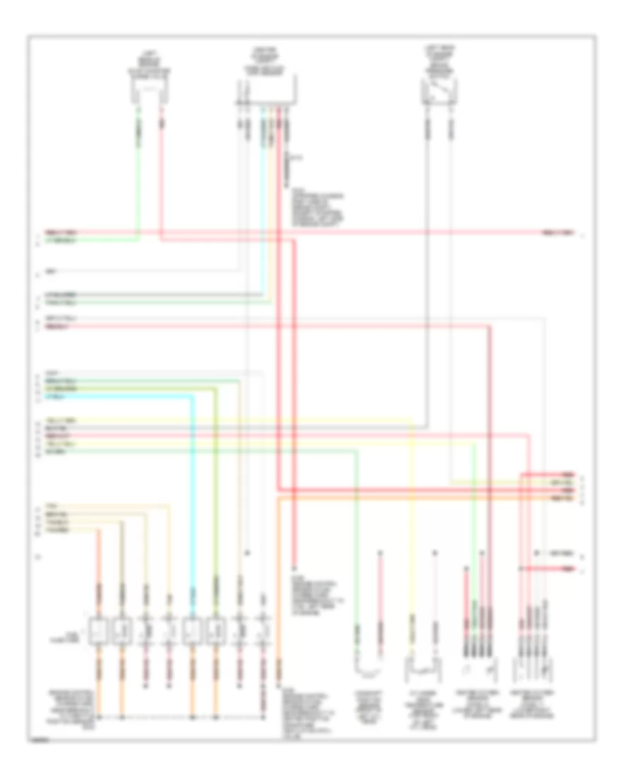
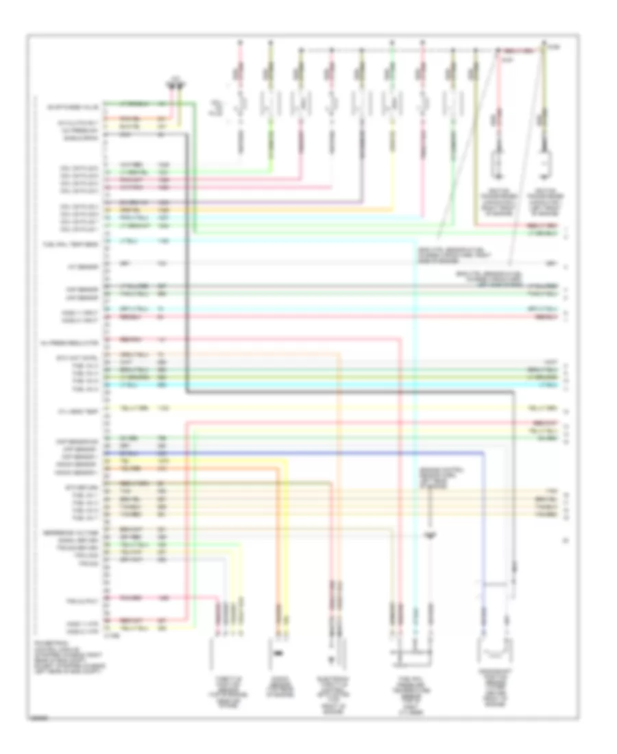
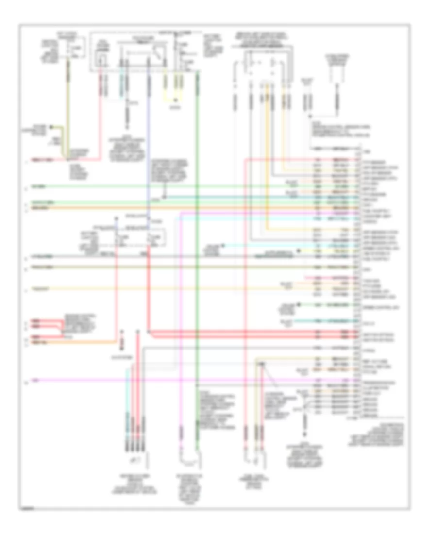
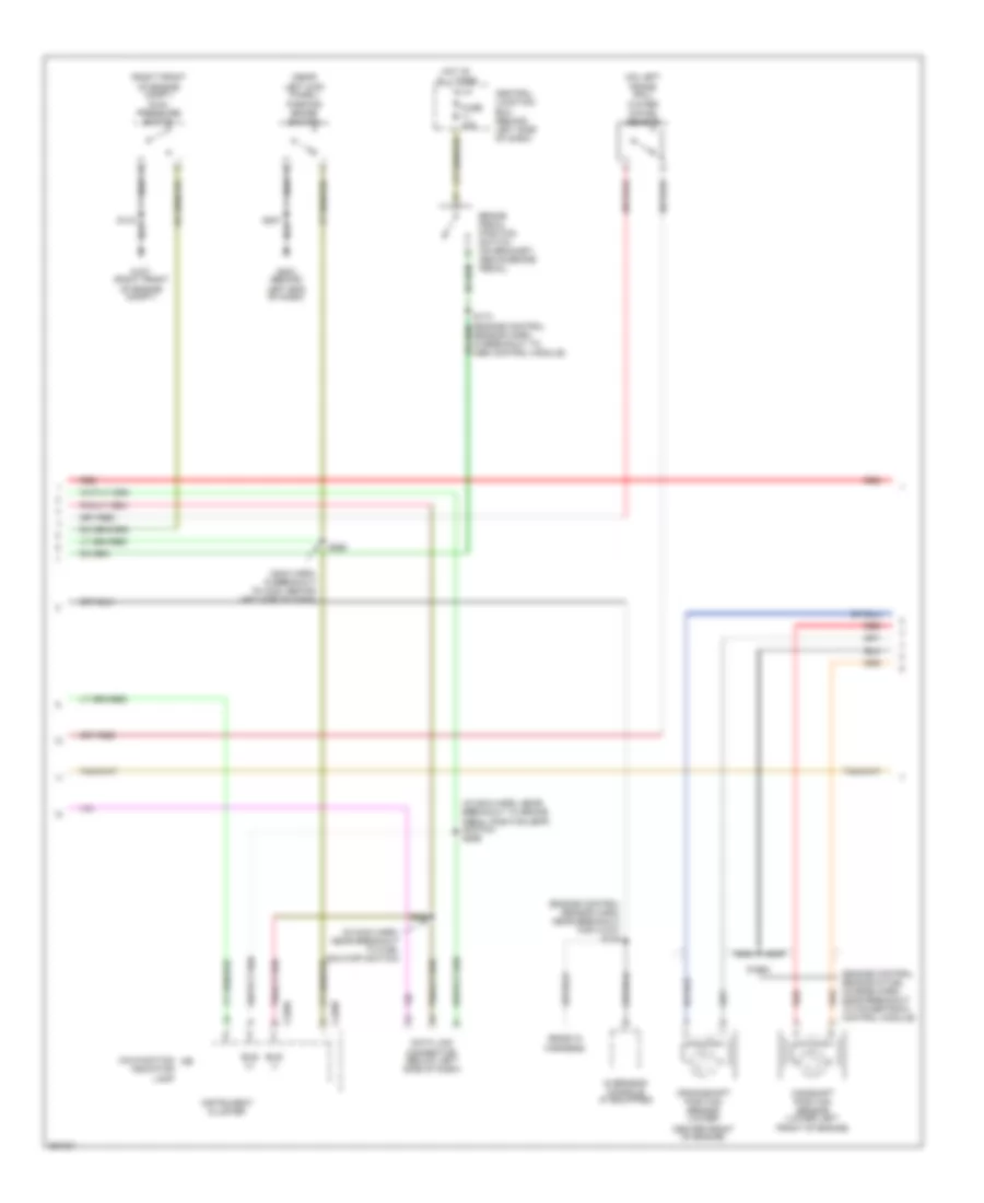
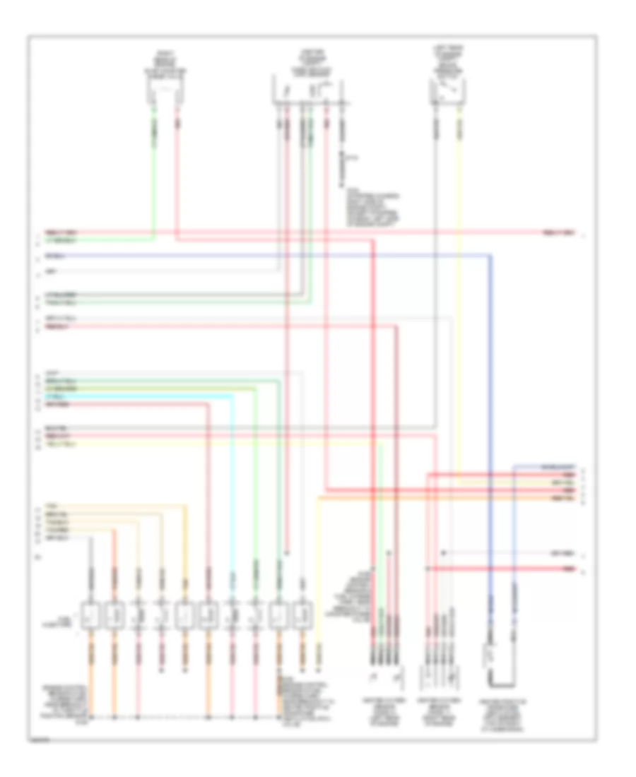
5.4L, Engine Performance Wiring Diagram, with Torqshift (2 of 5) for Ford E450 Super Duty 2007
 https://portal-diagnostov.com/license.html
Automotive Electricians Portal FZCO
Automotive Electricians Portal FZCO
https://portal-diagnostov.com/license.html
https://portal-diagnostov.com/license.html
Automotive Electricians Portal FZCO
Automotive Electricians Portal FZCOList of elements for 5.4L, Engine Performance Wiring Diagram, with Torqshift (2 of 5) for Ford E450 Super Duty 2007:
- (center
- (engine control sensor & fuel charge harn, near breakout to throttle position sensor) s155
- (left rear of engine compt) brake pressure switch
- (left rear of engine) evap canister purge valve
- Camshaft position sensor (front of left cyl head)
- Cylinder- head temperature sensor (top front of left cyl head)
- Fuel injectors
- G104 (stripped chassis: right side of engine compt) (except stripped chassis: left side of engine compt)
- Heated oxygen sensor (ho2s) 11 (lower right rear of engine)
- Heated oxygen sensor (ho2s) 21 (lower left rear of engine)
- Mass air flow (maf) sensor
- Nca
- Of engine compt)
- Red
- S159 (engine control sensor & fuel charge harn, near breakout to c192, left rear of engine)
- S160 (engine control sensor & fuel charge harn, near breakout to heated positive crankcase ventilation (pcv) valve)
- Tan
- Tan/red
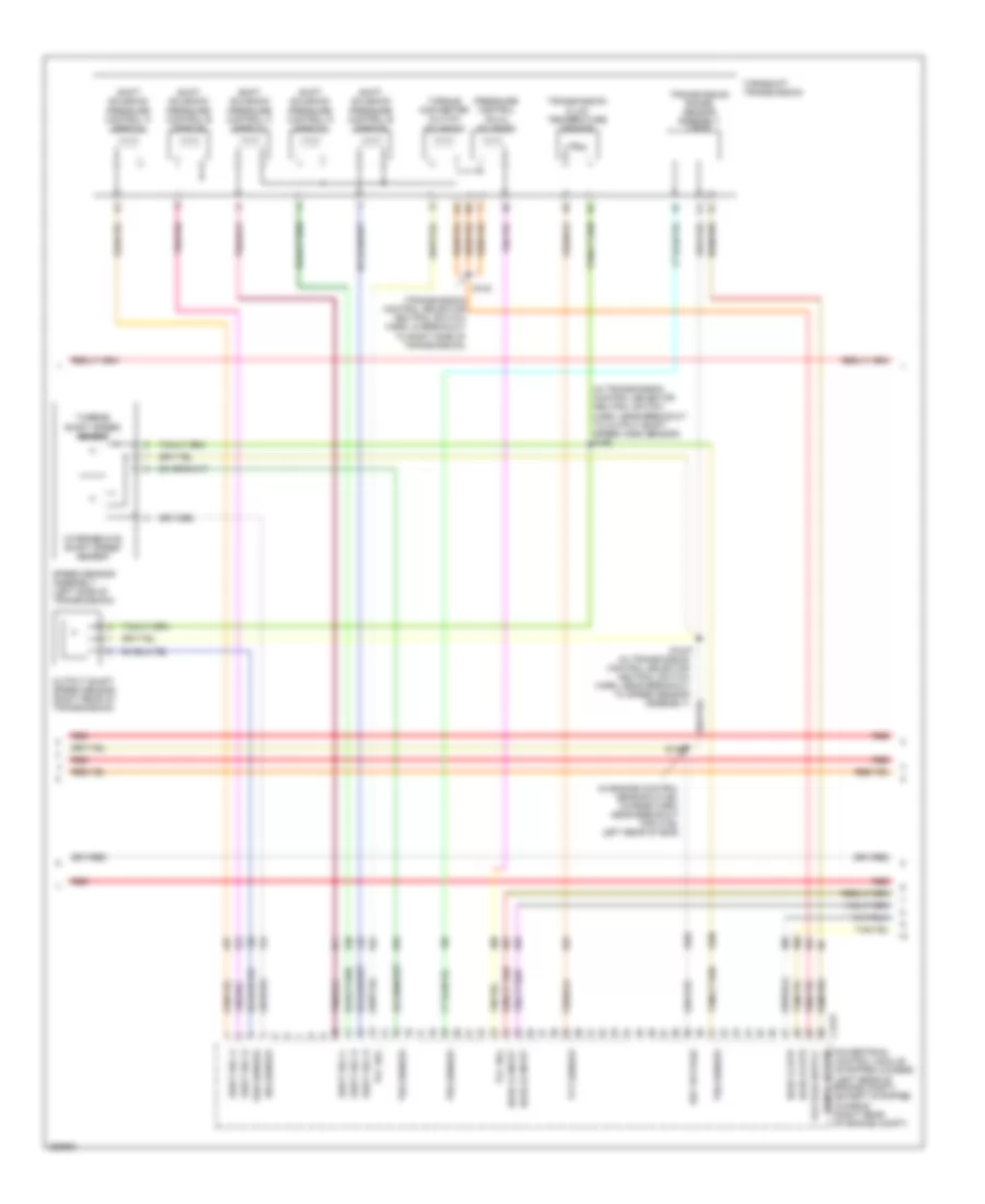
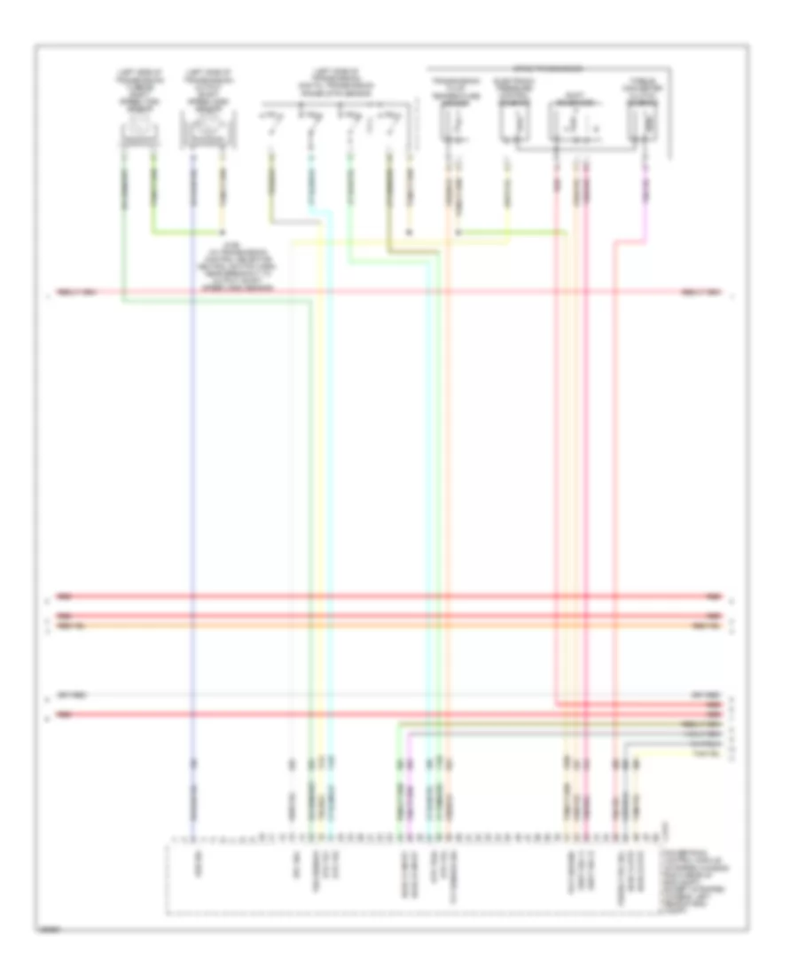
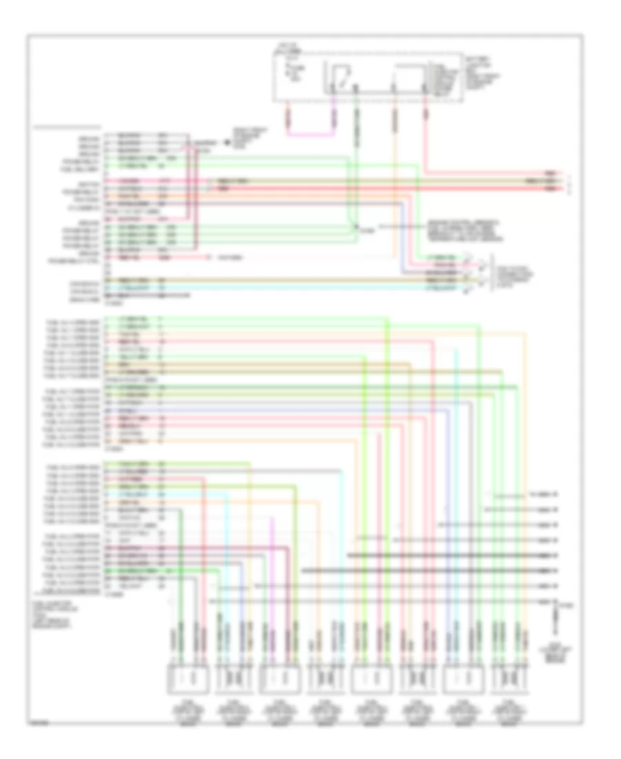
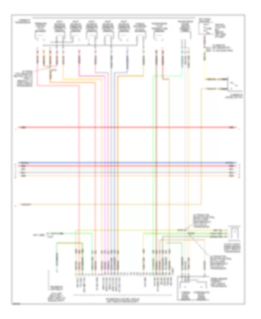
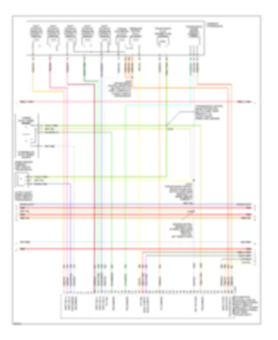
5.4L, Engine Performance Wiring Diagram, with Torqshift (3 of 5) for Ford E450 Super Duty 2007
 https://portal-diagnostov.com/license.html
Automotive Electricians Portal FZCO
Automotive Electricians Portal FZCO
https://portal-diagnostov.com/license.html
https://portal-diagnostov.com/license.html
Automotive Electricians Portal FZCO
Automotive Electricians Portal FZCOList of elements for 5.4L, Engine Performance Wiring Diagram, with Torqshift (3 of 5) for Ford E450 Super Duty 2007:
- (in engine control sensor & fuel charge harn, near breakout for c192, left rear of eng)
- (in transmission control selector neutral switch harn, near breakout to output shaft speed (oss) sensor) s198
- (transmission control selector neutral switch harn, in breakout to right side of transmission)
- C175t
- Ho2s 12 htr
- Ho2s 12 input
- Ho2s 22 htr
- Ho2s 22 input
- Intermediate shaft speed sensor
- Iss sensor
- Oss sensor
- Output shaft speed sensor (right rear of transmission)
- Powertrain control module (stripped chassis: (left rear of engine compt) (except stripped chassis: (right rear of engine compt)
- Pressure control (pc-a) solenoid
- Red
- Ref voltage
- S1037 (in transmission control selector neutral switch harn, near breakout to speed sensor assembly)
- S123
- S139
- Shift sol a
- Shift sol b
- Shift sol c
- Shift sol d
- Shift sol e
- Shift solenoid pressure control a (sspc-a)
- Shift solenoid pressure control b (sspc-b)
- Shift solenoid pressure control c (sspc-c)
- Shift solenoid pressure control d (sspc-d)
- Shift solenoid pressure control e (sspc-e)
- Signal return
- Speed sensor assembly (left side of transmission)
- Tcc sol
- Tft sensor
- Torqshift transmission
- Torque converter clutch solenoid
- Transmission fluid temperature sensor
- Transmission range sensor assembly (tr-p)
- Trs sensor
- Tss sensor
- Turbine shaft speed sensor
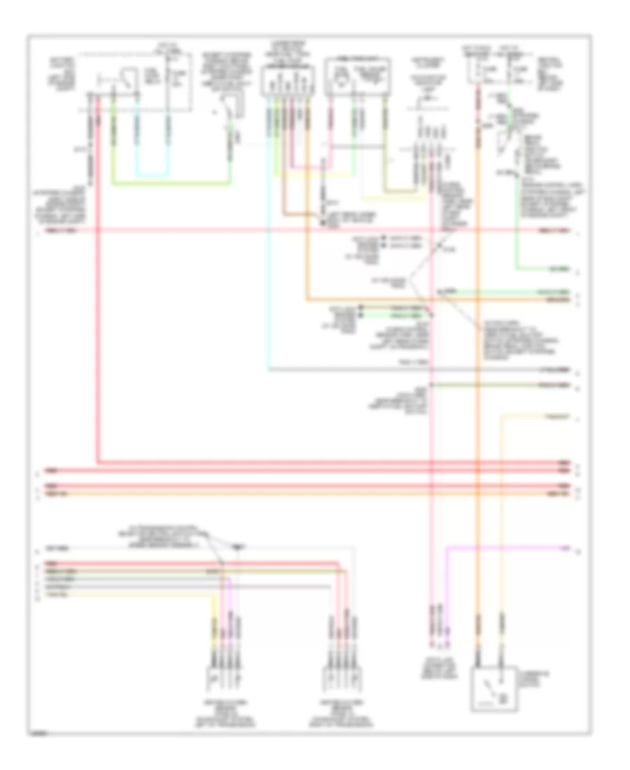
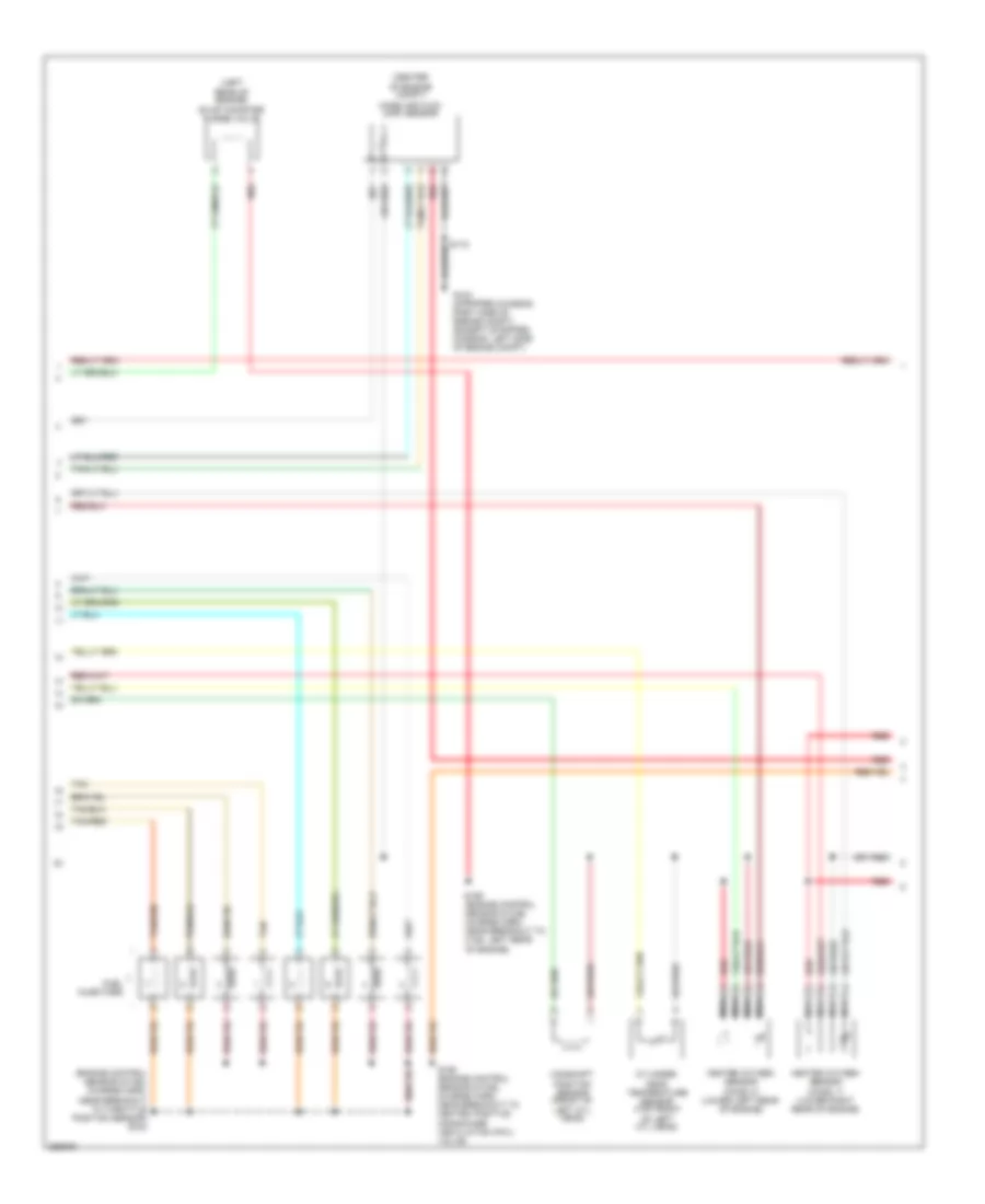
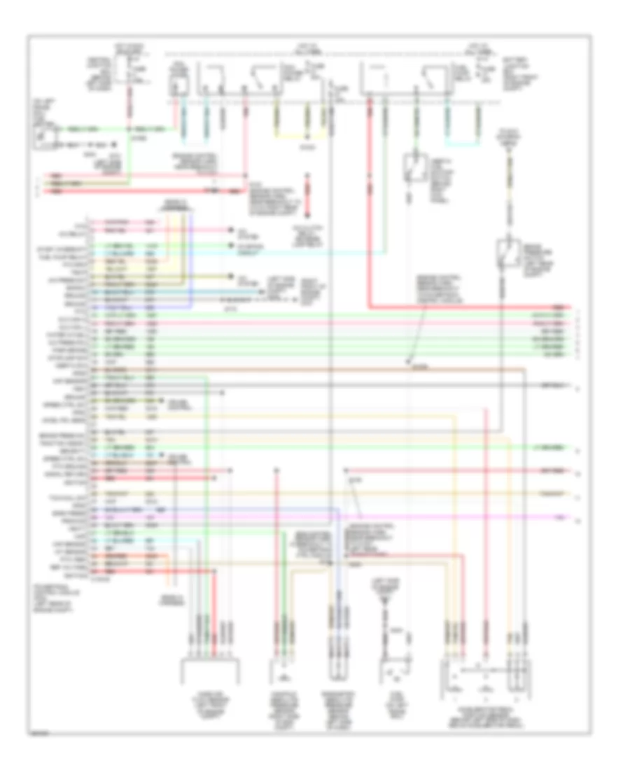
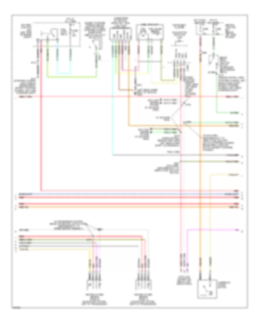
5.4L, Engine Performance Wiring Diagram, with Torqshift (4 of 5) for Ford E450 Super Duty 2007
 https://portal-diagnostov.com/license.html
Automotive Electricians Portal FZCO
Automotive Electricians Portal FZCO
https://portal-diagnostov.com/license.html
https://portal-diagnostov.com/license.html
Automotive Electricians Portal FZCO
Automotive Electricians Portal FZCOList of elements for 5.4L, Engine Performance Wiring Diagram, with Torqshift (4 of 5) for Ford E450 Super Duty 2007:
- (except stripped chassis: behind right kick panel) (stripped chassis: under dash) inertia fuel shut- off switch
- (in eng control sensor harn, near left rear of eng compt, on frame rail)
- (in main harn, near breakout to: inertia fuel shutoff switch (stripped chassis), brake pedal position switch (except stripped chassis))
- (in transmission control selector neutral switch harn, near breakout to speed sensor assembly)
- (left rear under- body of vehicle) g300
- (under rear of vehicle, near fuel tank) fuel pump driver module
- (w/ advance trac)
- Anti-lock brakes system (w/ advance trac)
- Battery junction box (left side of engine compt)
- Brake pedal position switch (on bracket above brake pedal)
- Bus +
- Bus -
- Central junction box (behind left side of dash)
- Chassis only)
- Data link connector (below left side of dash)
- Fp pwr
- Fp rtn
- Fpm
- Fuel gauge sensor
- Fuel lvl
- Fuel pump
- Fuel pump relay
- Fuel tank unit
- Fuse 10a
- Fuse 15a
- Fuse 20a
- G104 (stripped chassis: right side of engine compt) (except stripped chassis: left side of engine compt)
- Gnd
- Heated oxygen sensor (ho2s) 12 (on exhaust system, right of transmission)
- Heated oxygen sensor (ho2s) 22 (on exhaust system, left of transmission)
- Hot at all times
- Hot in run or start
- Ifs in
- Instrument cluster
- Malfunction indicator lamp
- Nca
- O/d off
- Overdrive cancel switch
- Red
- S100
- S102
- S146
- S148 (in eng control sensor harn, near left rear of eng compt, on frame rail)
- S172
- S174 (engine control harn,
- S228 (main harn, near breakout to inertia fuel shutoff switch)
- S260
- S269
- S312
- Stripped chassis: left rear of eng compt except stripped chassis: left front of engine compt)
- Vref
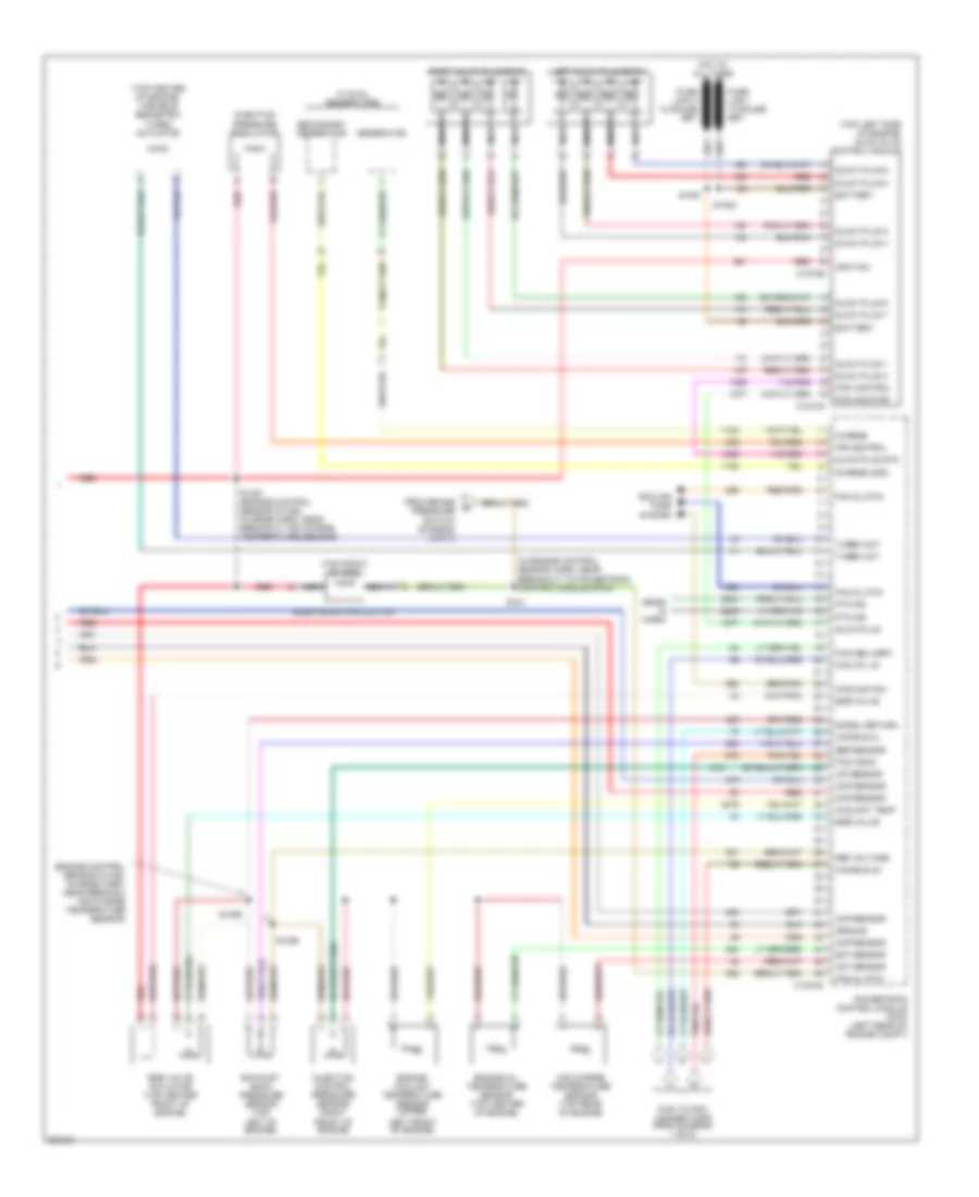
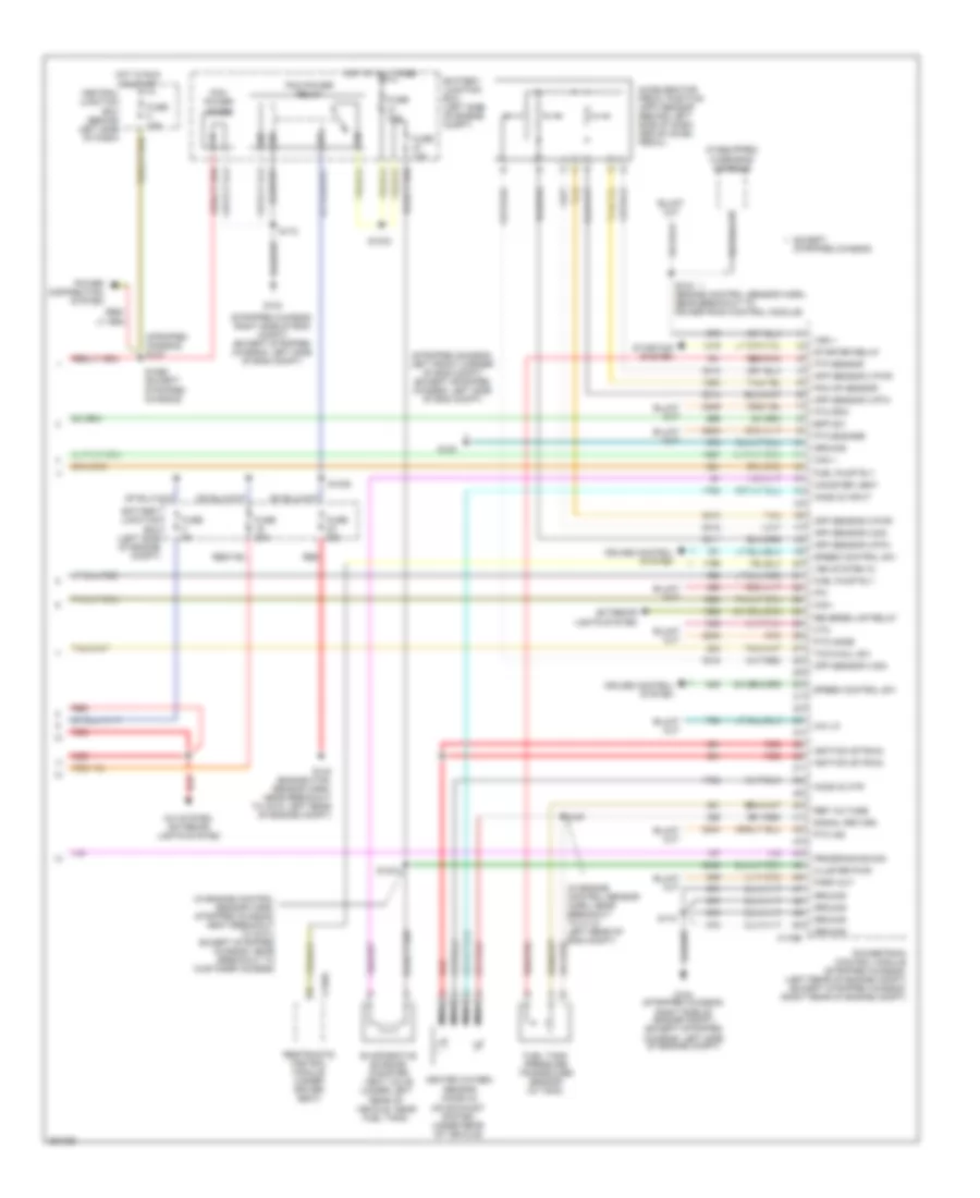
5.4L, Engine Performance Wiring Diagram, with Torqshift (5 of 5) for Ford E450 Super Duty 2007
 https://portal-diagnostov.com/license.html
Automotive Electricians Portal FZCO
Automotive Electricians Portal FZCO
https://portal-diagnostov.com/license.html
https://portal-diagnostov.com/license.html
Automotive Electricians Portal FZCO
Automotive Electricians Portal FZCOList of elements for 5.4L, Engine Performance Wiring Diagram, with Torqshift (5 of 5) for Ford E450 Super Duty 2007:
- (behind left side of dash, above accelerator pedal) accelerator pedal position (app) sensor
- (engine control sensor harn, near breakout to left rear of engine compt)
- (if equipped) overhead console
- (in eng control sensor harn, near breakout to c110, left rear of eng compt on frame rail)
- (stripped chassis) s127
- (stripped chassis: left front corner of engine compt) (except stripped chassis: left side of engine compt)
- 4x4 lo
- A/c system
- App sensor 2 pwr
- App sensor 2 rtn
- App sensor 2 sig
- App sensor 3 pwr
- App sensor 3 rtn
- App sensor 3 sig
- Battery junction box (left side of engine compt)
- Bpp sw
- C175b
- Can +
- Can -
- Canister vent
- Central junction box (behind left side of dash)
- Cluster pwr
- Cruise control system
- Evaporative emission canister vent valve (left rear of vehicle, near fuel tank)
- Exterior lights system
- Ftp sensor
- Fuel pump rly
- Fuel tank pressure (ftp) sensor (in tank)
- Fuse 10a
- Fuse 15a
- Fuse 20a
- Fuse 30a
- G100
- G104 (stripped chassis: right side of engine compt) (except stripped chassis: left side of engine compt)
- Ground
- Heated oxygen sensor (ho2s) 23 (on exhaust system, under rear of vehicle)
- Ho2s-23
- Hot at all times
- Hot in run or start
- Htr-23
- Ignition (st/run)
- Nca
- Od cancel sw
- Park out
- Pcm ap sensor
- Pcm power diode
- Pcm power relay
- Power distribution system
- Powertrain control module (stripped chassis: (left rear of engine compt) (except stripped chassis: (right rear of engine compt)
- Programming sig
- Pto engage
- Pto ind
- Pto mode
- Pto rpm
- Red
- Red/pnk
- Ref voltage
- Reverse lmp relay
- S1021 (in engine control sensor harn, stripped chassis: neat breakout to g101) except stripped chassis: near breakout to customer access)
- S1033
- S1035
- S1065 (except stripped chassis)
- S135 (engine control sensor harn, near breakout to powertrain control module)
- S142
- S157
- S172
- Signal return
- Speed control sw
- Starter relay
- Starting system
- Tach sig
- Tan
- Vem system in
- Vss
5.4L, Engine Performance Wiring Diagram, without Torqshift (1 of 5) for Ford E450 Super Duty 2007
 https://portal-diagnostov.com/license.html
Automotive Electricians Portal FZCO
Automotive Electricians Portal FZCO
https://portal-diagnostov.com/license.html
https://portal-diagnostov.com/license.html
Automotive Electricians Portal FZCO
Automotive Electricians Portal FZCOList of elements for 5.4L, Engine Performance Wiring Diagram, without Torqshift (1 of 5) for Ford E450 Super Duty 2007:
- (eng ctrl sensor & fuel charge wiring harn, left side of eng)
- (eng ctrl sensor & fuel charge wiring harn, right side of engine)
- (engine control sensor harn, left rear of engine)
- A/c clutch rly
- A/c press sw
- A/c system
- C175e
- Ckp sensor +
- Ckp sensor -
- Cmp sensor sig
- Coil on plug
- Coil on plug 1
- Coil on plug 2
- Coil on plug 3
- Coil on plug 4
- Coil on plug 5
- Coil on plug 6
- Coil on plug 7
- Coil on plug 8
- Crankshaft position sensor (lower center front of engine)
- Cyl head temp
- Electronic throttle control (etc) motor (top front of engine)
- Etc return
- Etc wot cntrl
- Evap purge valve
- Fuel inj 1
- Fuel inj 2
- Fuel inj 3
- Fuel inj 4
- Fuel inj 5
- Fuel inj 6
- Fuel inj 7
- Fuel inj 8
- Fuel rail pressure/ temperature sensor (top of right cylinder
- Fuel rail temp sens
- Ho2s 11 htr
- Ho2s 11 input
- Ho2s 21 htr
- Ho2s 21 input
- Iat sensor
- Ignition transformer capacitor 1 (left front of engine)
- Ignition transformer capacitor 2 (right front of engine)
- Inj press regulator
- Knock sensor (top rear of engine)
- Knock sensor +
- Knock sensor -
- Maf sensor
- Nca
- Powertrain control module (stripped chassis: right rear of eng compt, except stripped chassis: left rear of eng compt)
- Red/pnk
- Reference voltage
- S136
- S156
- S161
- Shield drain
- Signal return
- Tan
- Tan/red
- Throttle position sensor (top of engine, near air intake)
- Tps 2 sig
- Tps output
- Tps sig
- Tps sig return
5.4L, Engine Performance Wiring Diagram, without Torqshift (2 of 5) for Ford E450 Super Duty 2007
 https://portal-diagnostov.com/license.html
Automotive Electricians Portal FZCO
Automotive Electricians Portal FZCO
https://portal-diagnostov.com/license.html
https://portal-diagnostov.com/license.html
Automotive Electricians Portal FZCO
Automotive Electricians Portal FZCOList of elements for 5.4L, Engine Performance Wiring Diagram, without Torqshift (2 of 5) for Ford E450 Super Duty 2007:
- (center
- (engine control sensor & fuel charge harn, near breakout to throttle position sensor) s155
- (left rear of engine) evap canister purge valve
- Camshaft position sensor (front of left cyl head)
- Cylinder- head temperature sensor (top front of left cyl head)
- Fuel injectors
- G104 (stripped chassis: right side of engine compt) (except stripped chassis: left side of engine compt)
- Heated oxygen sensor (ho2s) 11 (lower right rear of engine)
- Heated oxygen sensor (ho2s) 21 (lower left rear of engine)
- Mass air flow (maf) sensor
- Nca
- Of engine compt)
- Red
- S159 (engine control sensor & fuel charge harn, near breakout to c192, left rear of engine)
- S160 (engine control sensor & fuel charge harn, near breakout to heated positive crankcase ventilation (pcv) valve)
- Tan
- Tan/red
5.4L, Engine Performance Wiring Diagram, without Torqshift (3 of 5) for Ford E450 Super Duty 2007
 https://portal-diagnostov.com/license.html
Automotive Electricians Portal FZCO
Automotive Electricians Portal FZCO
https://portal-diagnostov.com/license.html
https://portal-diagnostov.com/license.html
Automotive Electricians Portal FZCO
Automotive Electricians Portal FZCOList of elements for 5.4L, Engine Performance Wiring Diagram, without Torqshift (3 of 5) for Ford E450 Super Duty 2007:
- (in transmission control selector neutral switch harn, near breakout to output shaft speed (oss) sensor)
- (left side of transmission) digital transmission range (dtr) sensor
- (left side of transmission) output shaft speed (oss) sensor
- (left side of transmission) turbine shaft speed (tss) sensor
- 4r75e transmission
- C175t
- Dtr tr1
- Dtr tr2
- Dtr tr3a
- Dtr tr4
- Electronic pressure control solenoid
- Epc sol
- Ho2s 12 htr
- Ho2s 12 input
- Ho2s 22 htr
- Ho2s 22 input
- Oss sig
- Powertrain control module (stripped chassis: right rear of eng compt, except stripped chassis: left rear of eng compt)
- Press ctrl sol
- Red
- S198
- Shift sol a
- Shift sol b
- Shift solenoids
- Tft sensor sig
- Torque converter clutch solenoid
- Tr-p ground
- Tr1
- Tr2
- Tr3
- Tr4
- Transmission fluid temperature sensor
- Tss sensor
5.4L, Engine Performance Wiring Diagram, without Torqshift (4 of 5) for Ford E450 Super Duty 2007
 https://portal-diagnostov.com/license.html
Automotive Electricians Portal FZCO
Automotive Electricians Portal FZCO
https://portal-diagnostov.com/license.html
https://portal-diagnostov.com/license.html
Automotive Electricians Portal FZCO
Automotive Electricians Portal FZCOList of elements for 5.4L, Engine Performance Wiring Diagram, without Torqshift (4 of 5) for Ford E450 Super Duty 2007:
- (except stripped chassis: behind right kick panel) (stripped chassis: under dash) inertia fuel shut- off switch
- (in eng control sensor harn, near left rear of eng compt, on frame rail)
- (in main harn, near breakout to: inertia fuel shutoff switch (stripped chassis), brake pedal position switch (except stripped chassis))
- (in transmission control selector neutral switch harn, near breakout to c192, left rear of eng compt) s102
- (left rear under- body of vehicle) g300
- (under rear of vehicle, near fuel tank) fuel pump driver module
- (w/ advance trac)
- Anti-lock brakes system (w/ advance trac)
- Battery junction box (left side of engine compt)
- Brake pedal position switch (on bracket above brake pedal)
- Bus +
- Bus -
- Central junction box (behind left side of dash)
- Data link connector (below left side of dash)
- Fp pwr
- Fp rtn
- Fpm
- Fuel gauge sensor
- Fuel lvl
- Fuel pump
- Fuel pump relay
- Fuel tank unit
- Fuse 10a
- Fuse 15a
- Fuse 20a
- G104 (stripped chassis: right side of engine compt) (except stripped chassis: left side of engine compt)
- Gnd
- Heated oxygen sensor (ho2s) 12 (on exhaust system, right of transmission)
- Heated oxygen sensor (ho2s) 22 (on exhaust system, left of transmission)
- Hot at all times
- Hot in run or start
- Ifs in
- Instrument cluster
- Malfunction indicator lamp
- Nca
- O/d off
- Overdrive cancel switch
- Red
- S100
- S146
- S148 (in eng control sensor harn, near left rear of eng compt, on frame rail)
- S172
- S174 (engine control harn,
- S216
- S228 (main harn, near breakout to inertia fuel shutoff switch)
- S269
- S312
- Stripped chassis: left rear of eng compt except stripped chassis: left front of engine compt)
- Vref
5.4L, Engine Performance Wiring Diagram, without Torqshift (5 of 5) for Ford E450 Super Duty 2007
 https://portal-diagnostov.com/license.html
Automotive Electricians Portal FZCO
Automotive Electricians Portal FZCO
https://portal-diagnostov.com/license.html
https://portal-diagnostov.com/license.html
Automotive Electricians Portal FZCO
Automotive Electricians Portal FZCOList of elements for 5.4L, Engine Performance Wiring Diagram, without Torqshift (5 of 5) for Ford E450 Super Duty 2007:
- (behind left side of dash, above accelerator pedal) accelerator pedal position (app) sensor
- (engine control sensor harn, near breakout to left rear of engine compt)
- (if equipped) overhead console
- (in engine control sensor harn, near breakout to c110, left rear of eng compt)
- (stripped chassis) s127
- (stripped chassis: left front corner of engine compt) (except stripped chassis: left side of engine compt)
- 4x4 lo
- A/c system
- App sensor 2 pwr
- App sensor 2 rtn
- App sensor 2 sig
- App sensor 3 pwr
- App sensor 3 rtn
- App sensor 3 sig
- Battery junction box (left side of engine compt)
- Bpp sw
- C175b
- Can +
- Can -
- Canister vent
- Central junction box (behind left side of dash)
- Cluster pwr
- Cruise control system
- Evaporative emission canister vent valve (left rear of vehicle, near fuel tank)
- Ftp sensor
- Fuel pump rly
- Fuel tank pressure (ftp) sensor (in tank)
- Fuse 10a
- Fuse 15a
- Fuse 20a
- Fuse 30a
- G100
- G104 (stripped chassis: right side of engine compt) (except stripped chassis: left side of engine compt)
- Ground
- Heated oxygen sensor (ho2s) 23 (on exhaust system, under rear of vehicle)
- Ho2s-23
- Hot at all times
- Hot in run or start
- Htr-23
- Ignition (st/run)
- Nca
- Od cancel sw
- Park out
- Pcm ap sensor
- Pcm power diode
- Pcm power relay
- Power distribution system
- Powertrain control module (stripped chassis: (left rear of engine compt) (except stripped chassis: (right rear of engine compt)
- Programming sig
- Pto engage
- Pto ind
- Pto mode
- Pto rpm
- Red
- Red/pnk
- Ref voltage
- S1021 (in engine control sensor harn, stripped chassis: neat breakout to g101) except stripped chassis: near breakout to customer access)
- S1033
- S1035
- S1065 (except stripped chassis)
- S135 (engine control sensor harn, near breakout to powertrain control module)
- S142
- S157
- S172
- Signal return
- Speed control sw
- Tach sig
- Tan
- Vem system in
- Vss
6.0L DIESEL
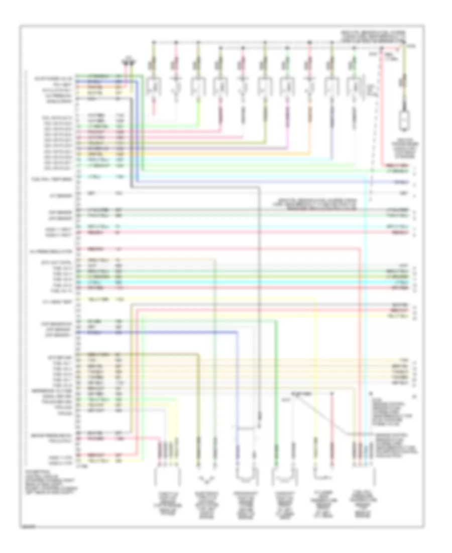
6.0L Diesel, Engine Performance Wiring Diagram (1 of 5) for Ford E450 Super Duty 2007
 https://portal-diagnostov.com/license.html
Automotive Electricians Portal FZCO
Automotive Electricians Portal FZCO
https://portal-diagnostov.com/license.html
https://portal-diagnostov.com/license.html
Automotive Electricians Portal FZCO
Automotive Electricians Portal FZCOList of elements for 6.0L Diesel, Engine Performance Wiring Diagram (1 of 5) for Ford E450 Super Duty 2007:
- (engine control sensor & fuel charge harn, near breakout to air charge temperature (act) sensor)
- (pins 11-21 not used)
- (pins 9-16 not used)
- (right front of engine compt) g106
- Battery junction box (right front of engine compt)
- C1388a
- C1388b
- C1388c
- Can bus 2h
- Can bus 2l
- Cylinder id
- Drain wire
- Ficm to pcm connections (to diagram 5 of 5)
- Fuel delivery
- Fuel inj 1 close gnd
- Fuel inj 1 close pwr
- Fuel inj 1 open gnd
- Fuel inj 1 open pwr
- Fuel inj 2 close gnd
- Fuel inj 2 close pwr
- Fuel inj 2 open gnd
- Fuel inj 2 open pwr
- Fuel inj 3 close gnd
- Fuel inj 3 close pwr
- Fuel inj 3 open gnd
- Fuel inj 3 open pwr
- Fuel inj 4 close gnd
- Fuel inj 4 close pwr
- Fuel inj 4 open gnd
- Fuel inj 4 open pwr
- Fuel inj 5 close gnd
- Fuel inj 5 close pwr
- Fuel inj 5 open gnd
- Fuel inj 5 open pwr
- Fuel inj 6 close gnd
- Fuel inj 6 close pwr
- Fuel inj 6 open gnd
- Fuel inj 6 open pwr
- Fuel inj 7 close gnd
- Fuel inj 7 close pwr
- Fuel inj 7 open gnd
- Fuel inj 7 open pwr
- Fuel inj 8 close gnd
- Fuel inj 8 close pwr
- Fuel inj 8 open gnd
- Fuel inj 8 open pwr
- Fuel injector 1 (top of right cylinder bank)
- Fuel injector 2 (top of left cylinder bank)
- Fuel injector 3 (top of right cylinder bank)
- Fuel injector 4 (top of left cylinder bank)
- Fuel injector 5 (top of right cylinder bank)
- Fuel injector 6 (top of left cylinder bank)
- Fuel injector 7 (top of right cylinder bank)
- Fuel injector 8 (top of left cylinder bank)
- Fuel injector control module (ficm) (left rear of engine compt)
- Fuel injector control module power relay
- Fuse 50a
- G108 (lower left rear of engine)
- Ground
- Hot at all times
- Ignition
- Nca
- Pcm comm
- Power relay
- Power relay ctrl
- Red
- S1060
- S1061
- S1062
6.0L Diesel, Engine Performance Wiring Diagram (2 of 5) for Ford E450 Super Duty 2007
 https://portal-diagnostov.com/license.html
Automotive Electricians Portal FZCO
Automotive Electricians Portal FZCO
https://portal-diagnostov.com/license.html
https://portal-diagnostov.com/license.html
Automotive Electricians Portal FZCO
Automotive Electricians Portal FZCOList of elements for 6.0L Diesel, Engine Performance Wiring Diagram (2 of 5) for Ford E450 Super Duty 2007:
- (ends in harness)
- (eng control sensor harn, in breakout to powertrain ctrl module) s138
- (engine control sensor harn, near breakout to c1047, left rear of eng compt)
- (engine control sensor harn, near breakout to c127)
- (engine control sensor harn, near breakout to powertrain control module)
- (left side of engine compt) g100
- (left side of engine compt) g101
- (on left frame rail) fuel heater
- (right front of engine compt) g107
- A/c clutch relay, reverse lamp relay
- A/c press sw
- A/c relay
- A/c system
- Accel pdl sens
- Accelerator pedal position sensor (behind left side of dash, above accelerator pedal)
- Aps2
- Aps3
- Baro press
- Barometric absolute pressure sensor (behind left side of dash)
- Battery junction box (right front of engine compt)
- Bcpsw
- Brake press sw
- Brake pressure switch (left rear of engine compt)
- C1381b
- Central junction box (behind left side of dash)
- Cruise control
- Cto
- Dlc can h
- Dlc can l
- Fuel pump (on left frame rail)
- Fuel pump relay
- Fuse 10a
- Fuse 15a
- Fuse 20a
- Fuse 30a
- G101 (left side of engine compt)
- Gen/batt
- Ground
- Hot at all times
- Hot in run or start
- Iat sensor
- Ignition
- Inertia fuel shutoff switch (behind right kick panel)
- Inertia sw
- Maf sensor
- Manifold absolute pressure sensor (right side of eng compt)
- Map
- Mass air- flow sensor (left front of engine compt)
- Nca
- Park brake
- Pcm power diode
- Pcm power relay
- Powertrain control module (pcm) (left rear of engine compt)
- Prog sig
- Pto
- Pto ground
- Pto rpm
- Pto vref
- Red
- Ref voltage
- S1033
- S1049
- S1065
- S1068
- S136
- S142 (engine control sensor harn, near breakout to c1019, right rear of engine compt)
- S172
- S200
- S404
- Signal return
- Speed ctrl sw
- Start interrupt
- Starting circuit
- Stoplamp sw
- Tan
- To s101 (diagram 5 of 5)
- Tow/haul sw
- Tr0-p
- Traction assist
- Vbatt
- Vss+
- Water in fuel
6.0L Diesel, Engine Performance Wiring Diagram (3 of 5) for Ford E450 Super Duty 2007
 https://portal-diagnostov.com/license.html
Automotive Electricians Portal FZCO
Automotive Electricians Portal FZCO
https://portal-diagnostov.com/license.html
https://portal-diagnostov.com/license.html
Automotive Electricians Portal FZCO
Automotive Electricians Portal FZCOList of elements for 6.0L Diesel, Engine Performance Wiring Diagram (3 of 5) for Ford E450 Super Duty 2007:
- (ends in harness)
- (engine control sensor & fuel charge harn, near breakout to powertrain control module)
- (engine control sensor harn, near breakout for c1047) s135
- (in main harn, near breakout to brake pedal position (bpp) switch) s269
- (in main harn, near breakout to fuel shutoff switch)
- (main harn, in breakout to c238, behind left side of dash)
- (near left kick panel) parking brake switch
- (on left frame rail) water- in-fuel sensor
- (right front of engine compt) dual pressure switch
- Brake pedal position switch (on bracket, above brake pedal)
- Bus (+)
- Bus (-)
- C220a
- C220b
- Camshaft position sensor (lower left front of engine)
- Center front of engine)
- Central junction box (behind left side of dash)
- Crankshaft position sensor (lower
- Data link connector (below left side of dash)
- Fuse 15a
- G107 (right front of engine compt)
- G203 (behind left end of dash)
- Hot at all times
- Instrument cluster
- Malfunction indicator lamp
- Nca
- Overhead console (if equipped)
- Red
- S1064
- S228
- S268
- Sensor harn, in breakout to abs control module)
6.0L Diesel, Engine Performance Wiring Diagram (4 of 5) for Ford E450 Super Duty 2007
 https://portal-diagnostov.com/license.html
Automotive Electricians Portal FZCO
Automotive Electricians Portal FZCO
https://portal-diagnostov.com/license.html
https://portal-diagnostov.com/license.html
Automotive Electricians Portal FZCO
Automotive Electricians Portal FZCOList of elements for 6.0L Diesel, Engine Performance Wiring Diagram (4 of 5) for Ford E450 Super Duty 2007:
- (in trans ctrl selector neutral switch harn, in breakout to right side of transmission)
- (in trans ctrl selector neutral switch harn, near breakout to c1148, at transmission)
- (not used)
- (w/ advance trac)
- (w/ remote keyless entry)
- Auxiliary relay box 1 (right front of engine compt)
- C1047
- C1381t
- Central junction box (behind left side of dash)
- Fuse 10a
- Hot in run or start
- Intermediate shaft speed sensor
- Iss sig
- Nca
- Oss sig
- Output shaft speed sensor (right rear of transmission)
- Overdrive cancel switch
- Pc sol pwr
- Pc-a sol
- Powertrain control module (left rear of engine compt)
- Pressure control (pc-a) solenoid
- Red
- Ref volt
- Rev lmp ctrl
- Reversing lamp relay
- S1037
- S123
- S198
- S215
- S260
- Shift solenoid pressure control a (sspc-a)
- Shift solenoid pressure control b (sspc-b)
- Shift solenoid pressure control c (sspc-c)
- Shift solenoid pressure control d (sspc-d)
- Shift solenoid pressure control e (sspc-e)
- Sig trn
- Speed sensor assembly (left side of transmission)
- Sspc-a crl
- Sspc-b ctrl
- Sspc-c crl
- Sspc-d ctrl
- Sspc-e ctrl
- Tcc sol ctrl
- Tft sens sig
- Torqshift transmission
- Torque converter clutch solenoid
- Tr-p gnd
- Tr-p sig
- Transmission fluid temperature sensor
- Transmission range sensor assembly (tr-p)
- Tss sig
- Turbine shaft speed sensor
6.0L Diesel, Engine Performance Wiring Diagram (5 of 5) for Ford E450 Super Duty 2007
 https://portal-diagnostov.com/license.html
Automotive Electricians Portal FZCO
Automotive Electricians Portal FZCO
https://portal-diagnostov.com/license.html
https://portal-diagnostov.com/license.html
Automotive Electricians Portal FZCO
Automotive Electricians Portal FZCOList of elements for 6.0L Diesel, Engine Performance Wiring Diagram (5 of 5) for Ford E450 Super Duty 2007:
- (ends in harn)
- (engine control sensor & fuel charge harn, near breakou air charge temperature sensor)
- (in engine control sensor harn, near breakout to powertrain control module (pcm))
- (top center of engine) variable geometric turbo actuator
- (top front of eng)
- (top left side of engine) glow plug control module
- Act sensor
- Air charge temperature sensor (top rear of engine)
- Battery
- C1273a
- C1273b
- C1381e
- Can bus 2h
- Can bus 2l
- Charge
- Charge (2nd)
- Ckp sensor
- Cmp sensor
- Coolant temp
- Cooling fan
- Cooling fans system
- Ebp sensor
- Egr valve
- Egr valve actuator (top center front of engine)
- Electronic fan clutch
- Engine coolant temperature sensor (upper
- Engine oil temperature sensor (top center of engine)
- Eot sensor
- Exhaust back pressure sensor (top left of engine)
- Fan clutch
- Ficm comm
- Ficm cyl id
- Ficm delivery
- Ficm to pcm connections (from diagram 1 of 5)
- From brake pressure switch (diagram 2 of 5)
- Generator
- Glow plug
- Glow plug 1
- Glow plug 2
- Glow plug 3
- Glow plug 4
- Glow plug 5
- Glow plug 6
- Glow plug 7
- Glow plug 8
- Glow plug sys
- Ground
- Hot at all times
- Icp sensor
- Ignition
- Injection control pressure sensor (right front of engine)
- Injection pressure regulator
- Ipr control
- Left front of engine)
- Left glow plug bank
- Nca
- Pcm control
- Pcm monitor
- Powertrain control module (pcm) (left rear of engine compt)
- Pto ind
- Red
- Ref voltage
- Right glow plug bank
- S101
- S1051
- S1054
- S1057 (engine control sensor & fuel charge harn, near breakout air charge temperature sensor)
- S1058
- S1059
- Secondary generator
- Signal return
- Turbo act
- W/ dual generators
6.8L
6.8L, Engine Performance Wiring Diagram (1 of 5) for Ford E450 Super Duty 2007
 https://portal-diagnostov.com/license.html
Automotive Electricians Portal FZCO
Automotive Electricians Portal FZCO
https://portal-diagnostov.com/license.html
https://portal-diagnostov.com/license.html
Automotive Electricians Portal FZCO
Automotive Electricians Portal FZCOList of elements for 6.8L, Engine Performance Wiring Diagram (1 of 5) for Ford E450 Super Duty 2007:
- (eng ctrl sensor & fuel charge wiring harn, near breakout to heated positive rankcase ventilation (pcv) valve)
- (eng ctrl sensor & fuel charge wiring harn, near breakout to throttle position sensor (tps))
- (engine control sensor & fuel charge harn, near breakout for powertrain control module (pcm))
- A/c clutch rly
- A/c press sw
- A/c system
- Brake pressure sw
- C175e
- Camshaft position sensor (front of left cylinder head)
- Ckp sensor +
- Ckp sensor -
- Cmp sensor sig
- Coil on plug
- Coil on plug 1
- Coil on plug 10
- Coil on plug 2
- Coil on plug 3
- Coil on plug 4
- Coil on plug 5
- Coil on plug 6
- Coil on plug 7
- Coil on plug 8
- Coil on plug 9
- Crankshaft position sensor (lower center front of engine)
- Cyl head temp
- Cylinder head temperature sensor (front of left cyl head)
- Electronic throttle control (etc) motor (top left side of engine)
- Etc return
- Etc wot cntrl
- Evap purge valve
- Fuel inj 1
- Fuel inj 10
- Fuel inj 2
- Fuel inj 3
- Fuel inj 4
- Fuel inj 5
- Fuel inj 6
- Fuel inj 7
- Fuel inj 8
- Fuel inj 9
- Fuel rail pressure/ temperature sensor (top rear of engine)
- Fuel rail temp sens
- Ho2s 11 htr
- Ho2s 11 input
- Ho2s 21 htr
- Ho2s 21 input
- Iat sensor
- Ignition transformer capacitor 1 (top front of engine)
- Inj press regulator
- Maf sensor
- Nca
- Pcv heat
- Powertrain control module (stripped chassis: right rear of eng compt, except stripped chassis: left rear of eng compt)
- Red/pnk
- Reference voltage
- S136 (engine control sensor & fuel charge harn, near breakout for evap canister purge valve)
- S137
- S161
- S162
- Shield drain
- Signal return
- Tan
- Tan/red
- Throttle position sensor (top of engine, near air intake)
- Tps 2 sig
- Tps output
- Tps sig
- Tps sig return
6.8L, Engine Performance Wiring Diagram (2 of 5) for Ford E450 Super Duty 2007
 https://portal-diagnostov.com/license.html
Automotive Electricians Portal FZCO
Automotive Electricians Portal FZCO
https://portal-diagnostov.com/license.html
https://portal-diagnostov.com/license.html
Automotive Electricians Portal FZCO
Automotive Electricians Portal FZCOList of elements for 6.8L, Engine Performance Wiring Diagram (2 of 5) for Ford E450 Super Duty 2007:
- (center of engine compt) mass air flow (maf) sensor
- (engine control sensor & fuel charge harn, near breakout to throttle position sensor) s155
- (left rear of engine compt) brake pressure switch
- (right rear of engine) evap canister purge valve
- Fuel injectors
- G104 (stripped chassis: right side of engine compt) (except stripped chassis: left side of engine compt)
- Heated oxygen sensor (ho2s) 11 (right rear of engine)
- Heated oxygen sensor (ho2s) 21 (left rear of engine)
- Heated positive crankcase ventilation (pcv) element (top of right cylinder bank)
- Nca
- Red
- S159 (engine control sensor & fuel charge harn, near breakout to canister purge valve)
- Tan
- Tan/red
6.8L, Engine Performance Wiring Diagram (3 of 5) for Ford E450 Super Duty 2007
 https://portal-diagnostov.com/license.html
Automotive Electricians Portal FZCO
Automotive Electricians Portal FZCO
https://portal-diagnostov.com/license.html
https://portal-diagnostov.com/license.html
Automotive Electricians Portal FZCO
Automotive Electricians Portal FZCOList of elements for 6.8L, Engine Performance Wiring Diagram (3 of 5) for Ford E450 Super Duty 2007:
- (engine control sensor & fuel charge harn, near breakout for c192, left rear of eng)
- (transmission control selector neutral switch harn, near breakout to output shaft speed (oss) sensor)
- C175t
- Ho2s 12 htr
- Ho2s 12 input
- Ho2s 22 htr
- Ho2s 22 input
- Intermediate shaft speed sensor
- Iss sensor
- Oss sensor
- Output shaft speed sensor (right rear of transmission)
- Powertrain control module (stripped chassis: right rear of eng compt, except stripped chassis: left rear of eng compt)
- Pressure control (pc-a) solenoid
- Red
- Ref voltage
- S1037 (transmission control selector neutral switch harn, near breakout to speed sensor assembly)
- S123 (transmission control selector neutral switch harn, in breakout to right side of transmission)
- S139
- S198
- Shift sol a
- Shift sol b
- Shift sol c
- Shift sol d
- Shift sol e
- Shift solenoid pressure control a (sspc-a)
- Shift solenoid pressure control b (sspc-b)
- Shift solenoid pressure control c (sspc-c)
- Shift solenoid pressure control d (sspc-d)
- Shift solenoid pressure control e (sspc-e)
- Signal return
- Speed sensor assembly (left side of transmission)
- Tcc sol
- Tft sensor
- Torqshift transmission
- Torque converter clutch solenoid
- Transmission fluid temperature sensor
- Transmission range sensor assembly (tr-p)
- Trs sensor
- Tss sensor
- Turbine shaft speed sensor
6.8L, Engine Performance Wiring Diagram (4 of 5) for Ford E450 Super Duty 2007
 https://portal-diagnostov.com/license.html
Automotive Electricians Portal FZCO
Automotive Electricians Portal FZCO
https://portal-diagnostov.com/license.html
https://portal-diagnostov.com/license.html
Automotive Electricians Portal FZCO
Automotive Electricians Portal FZCOList of elements for 6.8L, Engine Performance Wiring Diagram (4 of 5) for Ford E450 Super Duty 2007:
- (except stripped chassis: behind right kick panel) (stripped chassis: under dash) inertia fuel shut- off switch
- (in eng control sensor harn, near left rear of eng compt, on frame rail)
- (in main harn, near breakout to: inertia fuel shutoff switch (stripped chassis), brake pedal position switch (except stripped chassis))
- (in transmission control selector neutral switch harn, near breakout to speed sensor assembly)
- (left rear under- body of vehicle) g300
- (under rear of vehicle, near fuel tank) fuel pump driver module
- (w/ advance trac)
- Anti-lock brakes system (w/ advance trac)
- Battery junction box (left side of engine compt)
- Brake pedal position switch (on bracket above brake pedal)
- Bus +
- Bus -
- Central junction box (behind left side of dash)
- Data link connector (below left side of dash)
- Fp pwr
- Fp rtn
- Fpm
- Fuel gauge sensor
- Fuel lvl
- Fuel pump
- Fuel pump relay
- Fuel tank unit
- Fuse 10a
- Fuse 15a
- Fuse 20a
- G104 (stripped chassis: right side of engine compt) (except stripped chassis: left side of engine compt)
- Gnd
- Heated oxygen sensor (ho2s) 12 (on exhaust system, right of transmission)
- Heated oxygen sensor (ho2s) 22 (on exhaust system, left of transmission)
- Hot at all times
- Hot in run or start
- Ifs in
- Instrument cluster
- Malfunction indicator lamp
- Nca
- O/d off
- Overdrive cancel switch
- Red
- S100
- S102
- S146
- S148 (in eng control sensor harn, near left rear of eng compt, on frame rail)
- S172
- S174 (engine control harn,
- S228 (main harn, near breakout to inertia fuel shutoff switch)
- S260
- S269
- S312
- Stripped chassis: left rear of eng compt except stripped chassis: left front of engine compt)
- Vref
6.8L, Engine Performance Wiring Diagram (5 of 5) for Ford E450 Super Duty 2007
 https://portal-diagnostov.com/license.html
Automotive Electricians Portal FZCO
Automotive Electricians Portal FZCO
https://portal-diagnostov.com/license.html
https://portal-diagnostov.com/license.html
Automotive Electricians Portal FZCO
Automotive Electricians Portal FZCOList of elements for 6.8L, Engine Performance Wiring Diagram (5 of 5) for Ford E450 Super Duty 2007:
- (if equipped) overhead console
- (in engine control sensor harn, near breakout to c110, left rear of eng compt)
- (in engine control sensor harn, stripped chassis: neat breakout to g101) except stripped chassis: near breakout to customer access)
- (on exhaust system, under rear of vehicle)
- (stripped chassis) s127
- (stripped chassis: left front corner of eng compt) (except stripped chassis: left side of eng compt)
- (stripped chassis: right side of eng compt) (except stripped chassis: left side of eng compt)
- 4x4 lo
- A/c system, exterior lights system
- Accelerator pedal position (app) sensor (behind left side of dash, above accel pedal)
- App sensor 2 pwr
- App sensor 2 rtn
- App sensor 2 sig
- App sensor 3 pwr
- App sensor 3 rtn
- App sensor 3 sig
- Battery junction box (left side of engine compt)
- Bpp sw
- C175b
- C310a
- Can +
- Can -
- Canister vent
- Central junction box (behind left side of dash)
- Cluster pwr
- Cruise control system
- Cto
- Evaporative emission canister vent valve (under left rear of vehicle, near fuel tank)
- Except
- Exterior lights system
- Ftp sensor
- Fuel pump rly
- Fuel tank pressure transducer sensor (in tank)
- Fuse 10a
- Fuse 15a
- Fuse 20a
- Fuse 30a
- Fuse 5a
- G100
- G104
- G104 (stripped chassis: right side of engine compt) (except stripped chassis: left side of engine compt)
- Ground
- Heated oxygen sensor (ho2s) 23
- Ho2s 23 htr
- Ho2s 23 input
- Hot at all times
- Hot in run or start
- Ignition (st/run)
- Nca
- P/n
- Park out
- Pcm ap sensor
- Pcm power diode
- Pcm power relay
- Power distribution system
- Powertrain control module (stripped chassis: (left rear of engine compt) (except stripped chassis: (right rear of engine compt)
- Programming sig
- Pto engage
- Pto ind
- Pto mode
- Pto rpm
- Red
- Red/pnk
- Ref voltage
- Restraints control module (under driver seat)
- Reverse lmp relay
- S1021
- S1033
- S1035
- S1065 (except stripped chassis)
- S135 (engine control sensor harn, near breakout to powertrain control module)
- S142 (engine ctrl sensor harn, near breakout to c219, left rear of engine compt)
- S157
- S172
- Signal return
- Speed control sw
- Starter relay
- Starting system
- Stripped chassis
- Tan
- Tow/haul sw
- Vem system in
- Vss +

 Čeština
 Dansk
Dansk Deutsch
 Ελληνικά
 English
 English
 Español
 Suomi
Suomi Français
 Français
 עברית
עברית Hrvatski
 Magyar
 Italiano
 한국어
한국어 Nederlands
 Polski
 Português
 Português
 Română
 Русский
 Slovenčina
 Slovenščina
 Svenska
 Türkçe
 中文 (中国)
