ENGINE PERFORMANCE
2.3L
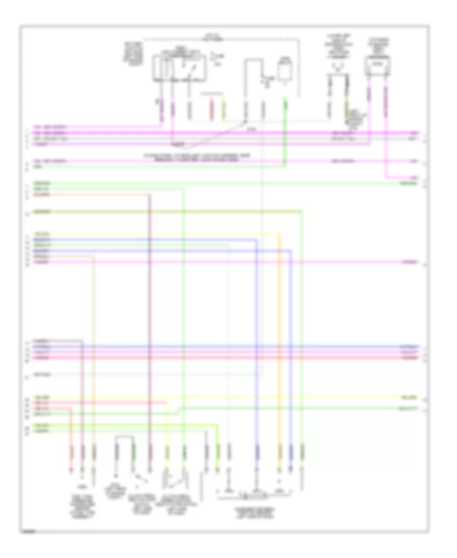
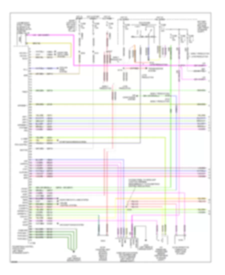
2.3L, Engine Performance Wiring Diagram (1 of 5) for Ford Fusion S 2007


List of elements for 2.3L, Engine Performance Wiring Diagram (1 of 5) for Ford Fusion S 2007:
- (in dash panel to headlamp junction harness, near breakout to powertrain control
- A/c evaporative thermistor (right side of dash)
- A/c pressure transducer sensor (right front of engine)
- Accr
- Acet
- Acpt
- Air conditioning system
- App 1
- App 2
- App 3
- Appsref 1
- Appsref 2
- Appsrtn 1
- Appsrtn 2
- Battery junction box (bjb) (left side of engine compt)
- Boo
- Bps
- C sigrtn
- C vref
- C175b
- C2280a
- Canvnt
- Case gnd
- Cbp18
- Cbp42
- Cbp46
- Ccb08
- Cdb08
- Cdc12
- Ce114
- Ce132
- Ce302
- Ce404
- Ce608
- Ce903
- Ce904
- Ces09
- Cet40
- Ch302
- Computer data lines system
- Cooling fans system
- Cpp bt
- Cpp tt
- Cruise control system
- Eair
- Eairm
- Early production
- Evap canister vent control solenoid (rear of vehicle chassis)
- Evaporative emission (evap) canister purge valve (lower right strut tower)
- Evmv
- Fc v
- Feps
- Fpc
- Fpm
- Ftpt
- Ftptref
- Fuse 15a
- Fuse 40a
- Fuse 7.5a
- G102 (left rear of engine compt)
- Gd120
- Hot at all times
- Hot in start or run
- Hs can +
- Hs can -
- Iat
- Ignition
- Injpwrm
- Kapwr
- Late production
- Le136
- Le137
- Le230
- Le424
- Maf
- Mafrtn
- Mass air flow/intake air temperature (maf/iat) sensor (left front of engine compt)
- Module (pcm))
- Output shaft speed (oss) sensor (top of transmission)
- Pcm control
- Pcm power relay
- Powertrain control module (pcm) (left rear of engine compt)
- Pwr gnd
- Pwr gnd 1
- Pwr gnd 2
- Pwr gnd 3
- Re136
- Re137
- Re325
- Re407
- Res08
- S121
- S124
- S127
- S129
- S143 (late production)
- S144
- Sbb45
- Sbp07
- Sccs
- Sccsrtn
- Smart junction box (sjb) (base of left "a" pillar)
- Smc
- Starting/charging system
- Trsw
- Vdb04
- Vdb05
- Ve225
- Ve701
- Ve702
- Ve703
- Ve740
- Ve806
- Ve808
- Ve922
- Vec03
- Ves10
- Vh406
- Vh433
- Vpwr
- Vpwr1
- Vssin
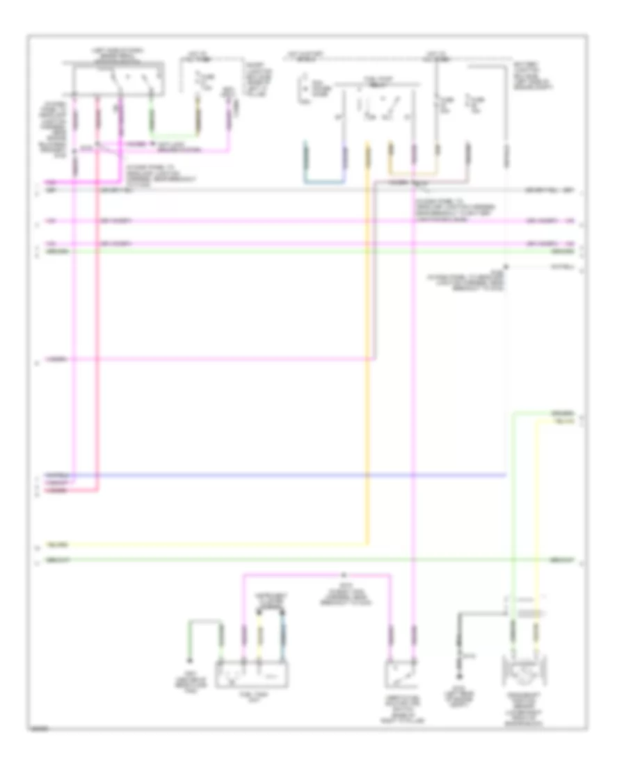
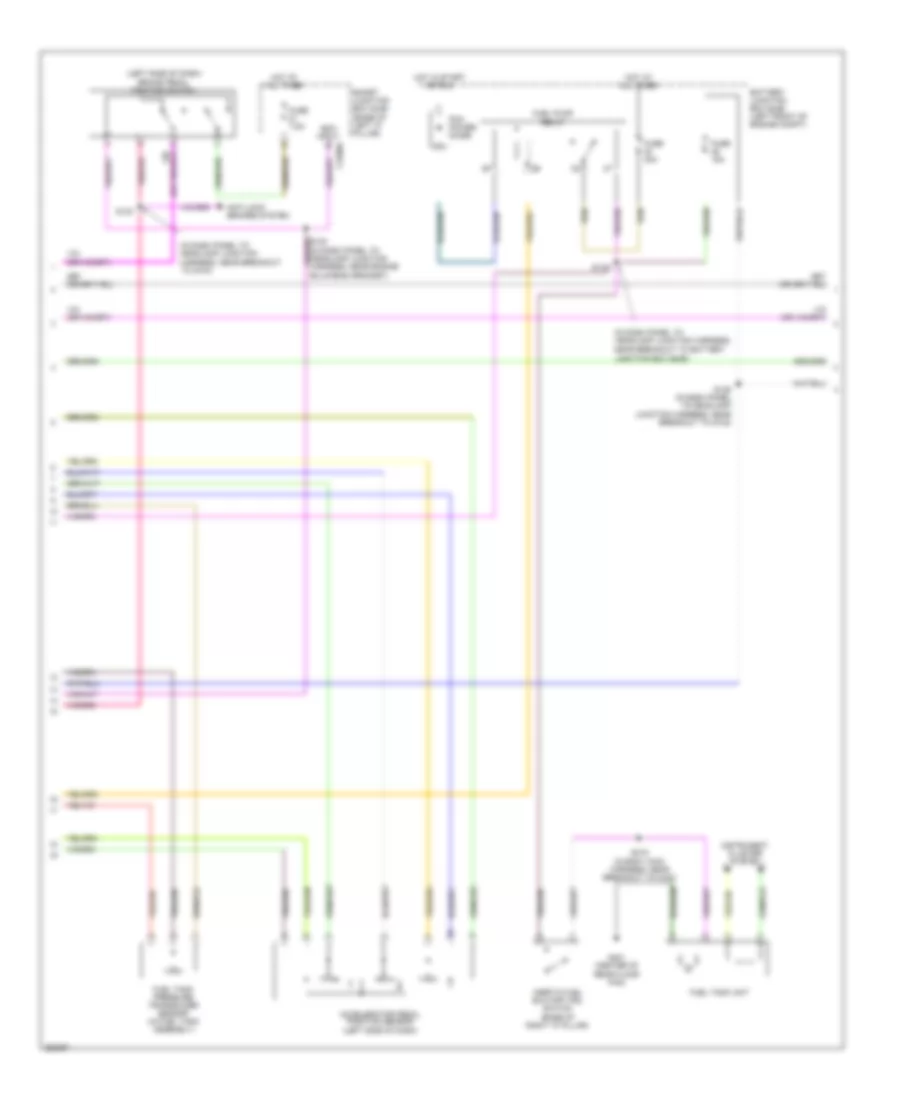
2.3L, Engine Performance Wiring Diagram (2 of 5) for Ford Fusion S 2007
List of elements for 2.3L, Engine Performance Wiring Diagram (2 of 5) for Ford Fusion S 2007:
- (in dash panel to headlamp junction harness, near breakout to battery junction box (bjb))
- (left front of engine compt) g103
- (lower left side of engine block) (pzev) peta pump motor
- (pzev) high current peta pump relay
- (top rear of engine) (pzev) peta solenoid
- Accelerator pedal position sensor (left side of dash)
- Battery junction box (bjb) (left side of engine compt)
- Clutch pedal position (cpp) switch (left side of dash)
- Clutch pedal speed control deactivator switch (left side of dash)
- Fnr5 relay
- Fuel tank pressure transducer sensor (in fuel tank assembly)
- Fuse 40a
- Fuse 5a
- G102 (left rear of engine compt)
- Hot at all times
- Nca
- S139
- S140
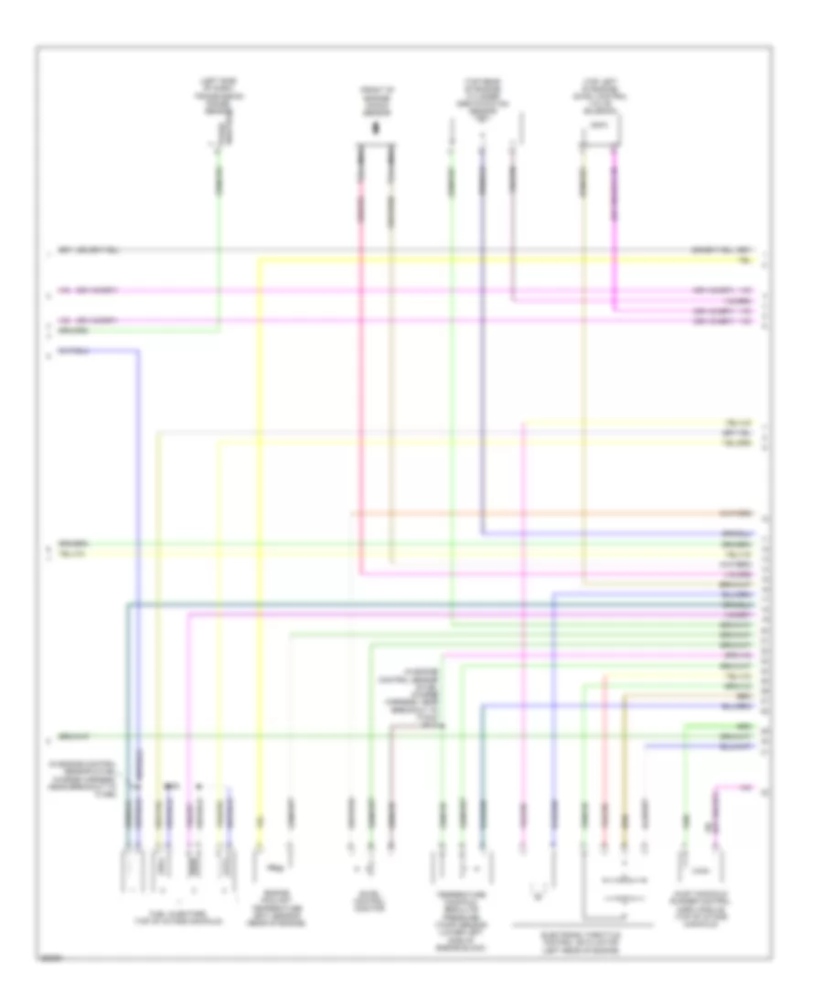
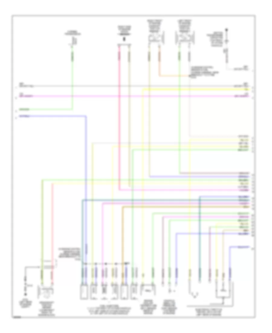
2.3L, Engine Performance Wiring Diagram (3 of 5) for Ford Fusion S 2007
List of elements for 2.3L, Engine Performance Wiring Diagram (3 of 5) for Ford Fusion S 2007:
- (in dash panel to headlamp junction harness, near breakout to battery
- (in dash panel to headlamp junction harness, near breakout to c1443)
- (in dash panel to headlamp junction harness, near engine bulkhead grommet) s120
- (left side of dash) brake pedal position switch
- Anti-lock brakes system
- Battery junction box (bjb) (left side of engine compt)
- Boo input c2280a
- Crankshaft position sensor (lower right front of engine block)
- Fuel pump relay
- Fuel tank unit
- Fuse 15a
- Fuse 30a
- Fuse 7.5a
- G102 (left rear of engine compt)
- G401 (center of rear floor pan)
- Hot at all times
- Hot in start or run
- Inertia fuel shutoff (ifs) switch (base of right "a" pillar)
- Instrument cluster system
- Junction box (bjb))
- Nca
- Pcm power diode
- S115
- S125 (in dash panel to headlamp junction harness, near breakout to g102)
- S130
- S133
- S415 (in body main harness, near breakout to c433)
- Smart junction box (sjb) (base of left "a" pillar)
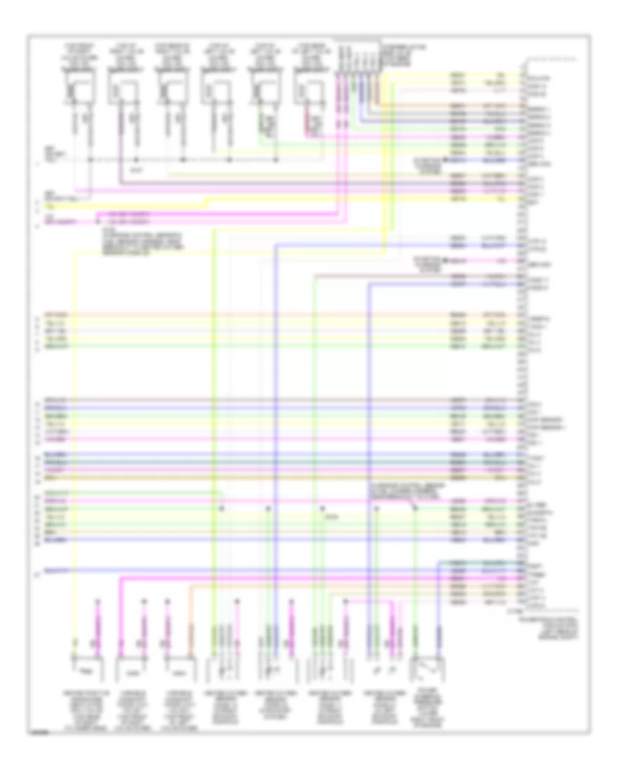
2.3L, Engine Performance Wiring Diagram (4 of 5) for Ford Fusion S 2007
List of elements for 2.3L, Engine Performance Wiring Diagram (4 of 5) for Ford Fusion S 2007:
- (front of engine) knock sensor
- (in engine control sensor & fuel charge harness, near breakout to c1368)
- (in engine control sensor & fuel charge harness, near breakout to c1543) s113
- (left side of dash) transmission range sensor
- (top left of engine) swirl control valve solenoid
- (top rear of engine) cylinder identification sensor
- Electronic throttle control (etc) motor (left rear of engine)
- Engine coolant temperature (ect) sensor (rear of engine)
- Fuel injectors (top of intake manifold)
- Inlet manifold runner control (imrc) module (top of intake manifold)
- Nca
- Park/ neutral
- S108
- Swirl control monitor
- Temperature manifold absolute pressure (tmap) sensor (lower left side of engine block)
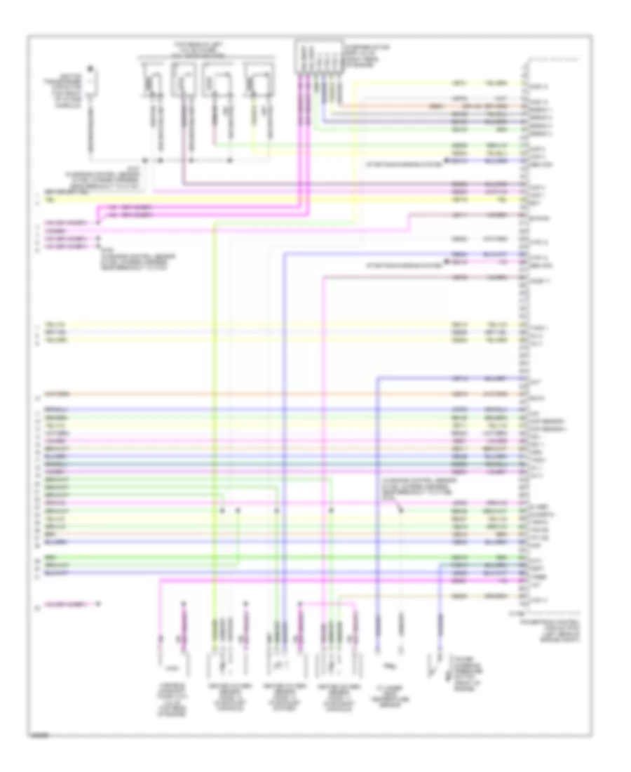
2.3L, Engine Performance Wiring Diagram (5 of 5) for Ford Fusion S 2007
List of elements for 2.3L, Engine Performance Wiring Diagram (5 of 5) for Ford Fusion S 2007:
- (in engine control sensor & fuel charge harness, near breakout to c175e) s102
- (top rear of left valve cover) coil on plugs (cop)
- Bvpwr
- C175e
- Cdc10
- Cdc15
- Ce102
- Ce103
- Ce104
- Ce205
- Ce206
- Ce207
- Ce208
- Ce233
- Ce234
- Ce235
- Ce301
- Ce303
- Ce304
- Ce305
- Ce306
- Ce316
- Ce411
- Ce412
- Ce421
- Ce426
- Cht
- Cid
- Ckp sensor +
- Ckp sensor -
- Cms 12
- Cms 13
- Cop 1
- Cop 2
- Cop 3
- Cop 4
- Ctrl 1
- Ctrl 2
- Ctrl 3
- Ctrl 4
- Cylinder- head temperature sensor
- E sigrtn
- E vref
- Ect
- Egrmc 1
- Egrmc 2
- Egrmc 3
- Egrmc 4
- Gen com
- Gen mon
- Heated oxygen sensor (ho2s) 11 (in exhaust manifold)
- Heated oxygen sensor (ho2s) 12 (in exhaust manifold)
- Heated oxygen sensor (ho2s) 13 (in exhaust system)
- Ho2s 11
- Htr 11
- Htr 12
- Htr 13
- Ignition transformer capacitor (top front of intake
- Imrc
- Imtv
- Inj 1
- Inj 2
- Inj 3
- Inj 4
- Ks1 +
- Ks1 -
- Le111
- Le423
- Le428
- Manifold)
- Map
- Power steering pressure switch (front of engine)
- Powertrain control module (pcm) (left rear of engine compt)
- Pspt
- Re135
- Re323
- Re405
- Re427
- S107 (in engine control sensor & fuel charge harness, near breakout to c1161)
- S109 (in engine control sensor & fuel charge harness, near breakout to c191)
- Scvm
- Starting/charging system
- Stepper motor egr valve (right rear of engine)
- Tacm +
- Tacm -
- Tp1 ns
- Tp2 ps
- Tpref
- Tprtn
- Variable camshaft timing (vct) valve (top rear of engine)
- Vcs10
- Vct
- Ve519
- Ve706
- Ve711
- Ve712
- Ve716
- Ve731
- Ve733
- Ve735
- Ve801
- Ve803
- Ve818
- Ve819
- Vol supp
- Vol supp vol supp
3.0L
3.0L, Engine Performance Wiring Diagram (1 of 4) for Ford Fusion S 2007
List of elements for 3.0L, Engine Performance Wiring Diagram (1 of 4) for Ford Fusion S 2007:
- (early production) s129
- (in dash panel to headlamp junction harness, near breakout to powertrain control module (pcm))
- (lower right strut tower) evaporative emission (evap) canister purge valve
- (or cbp47)
- A/c evaporative thermistor (right side of dash)
- A/c pressure transducer sensor (center rear of engine compt)
- Accr
- Acet
- Acpt
- Air conditioning system
- App 1
- App 2
- App 3
- Appsref 1
- Appsref 2
- Appsrtn 1
- Appsrtn 2
- Battery junction box (bjb) (left front of engine compt)
- Boo
- Bps
- C sigrtn
- C vref
- C175b
- C2280a
- C2280b
- Canvnt
- Case gnd
- Cbp13
- Cbp18
- Cbp42
- Cbp46
- Cbp47
- Ccb08
- Cdb08
- Cdc12
- Ce114
- Ce132
- Ce302
- Ce608
- Ces09
- Cet40
- Ch302
- Computer data lines system
- Cooling fans system
- Cruise control system
- Early production
- Evap canister vent control solenoid (rear of vehicle chassis)
- Evmv
- Fc v
- Feps
- Fpc
- Fpm
- Ftpt
- Ftptref
- Fuse 10a
- Fuse 15a
- Fuse 40a
- Fuse 7.5a
- G102 (left rear of engine compt)
- Gd120
- Hot at all times
- Hot in start
- Hot in start or run
- Hs can +
- Hs can -
- Iat
- Ignition
- Injpwrm
- Kapwr
- Late production
- Le136
- Le137
- Le230
- Le424
- Maf
- Mafrtn
- Mass air flow/intake air temperature (maf/iat) sensor (left front of engine compt)
- Pcm control
- Pcm power relay
- Powertrain control module (pcm) (left rear of engine compt)
- Pwr gnd
- Pwr gnd 1
- Pwr gnd 2
- Pwr gnd 3
- Re136
- Re137
- Re325
- Re407
- Res08
- S119
- S121
- S124
- S127
- S142 (early production)
- S143 (late production)
- S144
- S232
- Sbp07
- Sccs
- Sccsrtn
- Smart junction box (sjb) (base of left "a" pillar)
- Smc
- Smr
- Starting/charging system
- Transmissions system
- Trsw
- Vdb04
- Vdb05
- Ve225
- Ve701
- Ve702
- Ve703
- Ve740
- Ve808
- Ve922
- Vec03
- Ves10
- Vh406
- Vh433
- Vpwr
- Vpwr1
3.0L, Engine Performance Wiring Diagram (2 of 4) for Ford Fusion S 2007
List of elements for 3.0L, Engine Performance Wiring Diagram (2 of 4) for Ford Fusion S 2007:
- (in dash panel to headlamp junction harness, near breakout to battery
- (in dash panel to headlamp junction harness, near breakout to g103)
- (left side of dash) brake pedal position switch
- Accelerator pedal position sensor (left side of dash)
- Anti-lock brakes system
- Battery junction box (bjb) (left front of engine compt)
- Boo input c2280a
- Fuel pump relay
- Fuel tank pressure transducer sensor (in fuel tank assembly)
- Fuel tank unit
- Fuse 15a
- Fuse 30a
- Fuse 7.5a
- G401 (center of rear floor pan)
- Hot at all times
- Hot in start or run
- Inertia fuel shutoff (ifs) switch (base of right "a" pillar)
- Instrument cluster system
- Junction box (bjb))
- Pcm power diode
- S125 (in dash panel to headlamp junction harness, near breakout to g102)
- S130
- S133
- S415 (in body main harness, near breakout to c433)
- Smart junction box (sjb) (base of left "a" pillar)
3.0L, Engine Performance Wiring Diagram (3 of 4) for Ford Fusion S 2007
List of elements for 3.0L, Engine Performance Wiring Diagram (3 of 4) for Ford Fusion S 2007:
- (in engine control sensor & fuel charge harness, near breakout to c175e) s103
- (in engine control sensor & fuel charge harness, near breakout to c181)
- (left front of engine) camshaft position sensor 2
- (right front of engine) camshaft position sensor 1
- (right side of engine) knock sensor
- 6 speed transmission
- Crankshaft position sensor (lower right front of engine block)
- Electronic throttle control (etc) motor (left rear of engine)
- Engine coolant temperature (ect) sensor (rear of engine)
- Fuel injectors (1, 2, 3: top right of intake manifold) (5, 6: left side of intake manifold) (4: top left of intake manifold)
- G102 (left rear of engine compt)
- Ignition transformer capacitor (top front of intake
- Lock start
- Manifold absolute pressure (map) sensor (top rear of engine)
- Manifold)
- Nca
- S108
- S115
3.0L, Engine Performance Wiring Diagram (4 of 4) for Ford Fusion S 2007
List of elements for 3.0L, Engine Performance Wiring Diagram (4 of 4) for Ford Fusion S 2007:
- (in engine control sensor & fuel charge harness, near breakout to c1450)
- (top front of right valve cover) coil on plugs (cop) 1
- (top of right valve cover) coil on plugs (cop) 2
- (top of left valve cover) coil on plugs (cop) 4
- (top of left valve cover) coil on plugs (cop) 5
- (top rear of right valve cover) coil on plugs (cop) 3
- (top rear of left valve cover) coil on plugs (cop) 6
- C175e
- Cdc10
- Cdc15
- Ce102
- Ce103
- Ce104
- Ce205
- Ce206
- Ce207
- Ce208
- Ce209
- Ce210
- Ce233
- Ce234
- Ce235
- Ce236
- Ce301
- Ce303
- Ce304
- Ce305
- Ce306
- Ce307
- Ce308
- Ce321
- Ce412
- Ce421
- Ce422
- Ce426
- Cid 1
- Cid 2
- Ckp sensor +
- Ckp sensor -
- Cms 12
- Cms 22
- Cop 1
- Cop 2
- Cop 3
- Cop 4
- Cop 5
- Cop 6
- Ctrl 1
- Ctrl 2
- Ctrl 3
- Ctrl 4
- E sigrtn
- E vref
- Ect
- Egrmc 1
- Egrmc 2
- Egrmc 3
- Egrmc 4
- Gen com
- Gen mon
- Heated oxygen sensor (ho2s) 11 (in right exhaust manifold)
- Heated oxygen sensor (ho2s) 12 (in right exhaust manifold)
- Heated oxygen sensor (ho2s) 21 (in left exhaust manifold)
- Heated oxygen sensor (ho2s) 22 (in exhaust system)
- Heated positive crankcase ventilation (pcv) valve (top rear of right cylinder head)
- Ho2s 11
- Ho2s 21
- Htr 11
- Htr 12
- Htr 21
- Htr 22
- Inj 1
- Inj 2
- Inj 3
- Inj 4
- Inj 5
- Inj 6
- Ks1 +
- Ks1 -
- Le423
- Le428
- Map
- Pcvhtr
- Power steering pressure switch (lower right front of engine)
- Powertrain control module (pcm) (left rear of engine compt)
- Pspt
- Re135
- Re323
- Re405
- Re427
- Re429
- S102
- S107
- S149 (in engine control sensor & fuel sensor harness, near breakout to heated oxygen sensor (ho2s) 22)
- Starting/ charging system
- Stepper motor egr valve (top rear of engine)
- Tacm +
- Tacm -
- Tp1 ns
- Tp2 ps
- Tpref
- Tprtn
- Variable camshaft timing (vct) valve 1 (top front of right valve cover)
- Variable camshaft timing (vct) valve 2 (top front of left valve cover)
- Vcs10
- Vct
- Vct 2
- Ve706
- Ve707
- Ve711
- Ve716
- Ve731
- Ve733
- Ve735
- Ve737
- Ve801
- Ve803
- Ve818
- Ve819
- Vol supp
- Vol supp vol supp
- Vrsrtn

 Čeština
 Dansk
Dansk Deutsch
 Ελληνικά
 English
 English
 Español
 Suomi
Suomi Français
 Français
 עברית
עברית Hrvatski
 Magyar
 Italiano
 한국어
한국어 Nederlands
 Polski
 Português
 Português
 Română
 Русский
 Slovenčina
 Slovenščina
 Svenska
 Türkçe
 中文 (中国)