POWER DISTRIBUTION
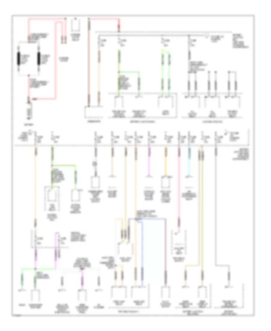
Power Distribution Wiring Diagram (1 of 4) for Ford Expedition 1999
 https://portal-diagnostov.com/license.html
Automotive Electricians Portal FZCO
Automotive Electricians Portal FZCO
https://portal-diagnostov.com/license.html
https://portal-diagnostov.com/license.html
Automotive Electricians Portal FZCO
Automotive Electricians Portal FZCO
List of elements for Power Distribution Wiring Diagram (1 of 4) for Ford Expedition 1999:
- (body harn, near breakout to lock relay block) s216
- (cable assembly harness, near battery) red s1001
- (console panel harn, near console blower motor) s305
- (main harn, near breakout to main light switch) s212
- (main harn, near passenger's air bag) s2013
- Air suspension compressor relay
- All lock relay
- All unlock relay
- Anti-lock brake system module (4wabs)
- Auxiliary a/c relay
- Auxiliary power socket
- Battery
- Battery junction box
- Battery junction box (left side of engine compartment)
- Battery junction relay box
- C113
- C147
- Cd changer
- Cellular telephone suport electronics
- Central junction box (under left side of dash)
- Console auxiliary power socket
- Daytime running lamps resistor
- Driver's unlock relay
- Fog lamp relay
- From a fuse 8 (diagram 1 of 4)
- Fuse 10a
- Fuse 15a
- Fuse 20a
- Fuse 25a
- Fuse 30a
- Fuse 50a
- Generator
- Headlamp relay
- Horn relay
- Lock relay block
- Main light switch
- Multi- function switch
- Nca
- Park lamp relay
- Passenger's power seat control switch
- Radio
- Rear integrated control panel
- Rear wiper down relay
- Rear wiper up relay
- Red
- Rpo relay block 1
- Rpo relay block 2
- S1002 (cable assembly harness, near battery)
- S108 (engine compt harn, in breakout to bjb)
- S109 (engine harness, left side of engine compt)
- S2012 (main harn, near radio)
- Starter motor
- Starter motor relay
- Subwoofer amplifier
- To fuse (diagram 2 of 4)
- To fuse 103 (diagram 1 of 4)
- Trailer tow backup lamp relay
- Trailer tow battery charge relay
- Trailer tow running lamp relay
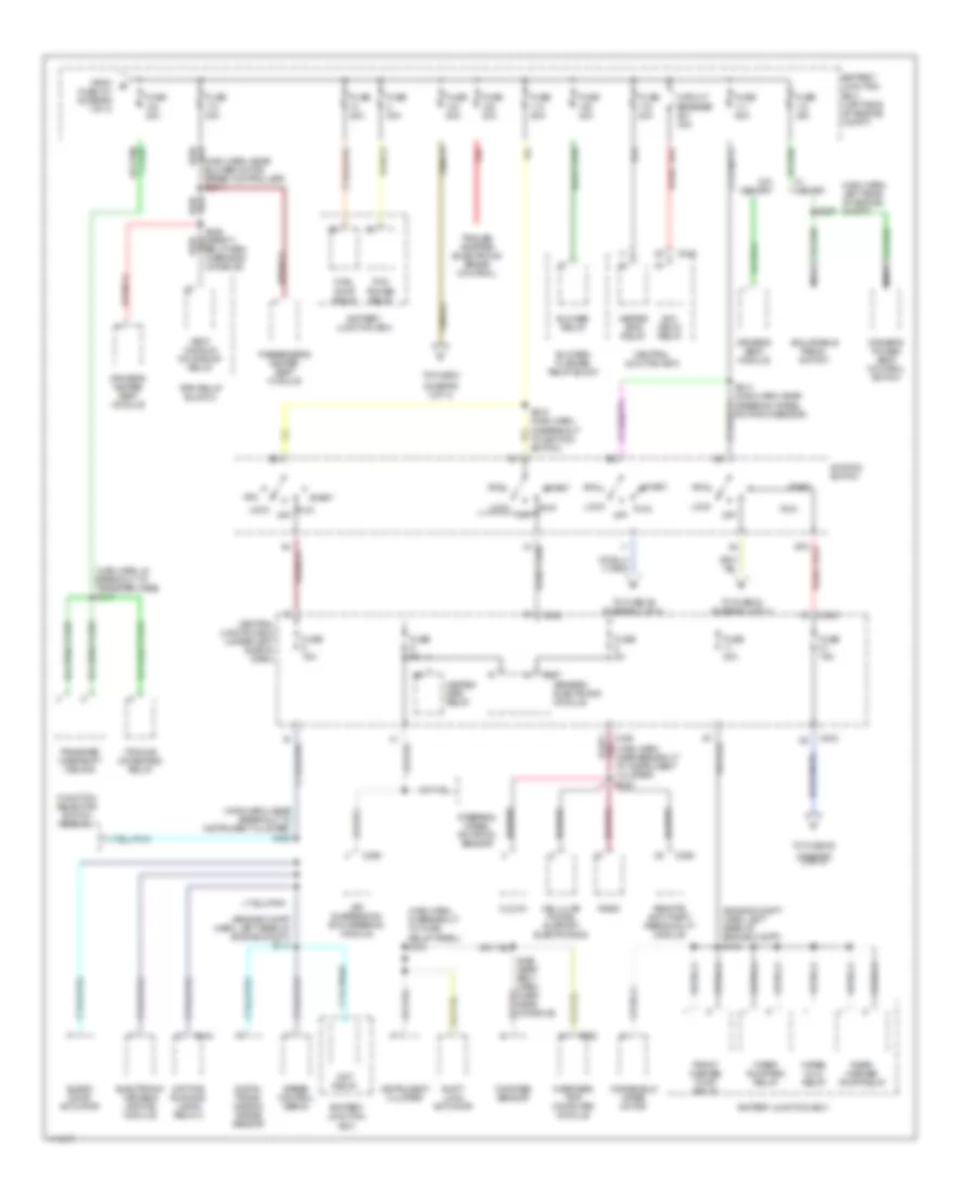
Power Distribution Wiring Diagram (2 of 4) for Ford Expedition 1999
 https://portal-diagnostov.com/license.html
Automotive Electricians Portal FZCO
Automotive Electricians Portal FZCO
https://portal-diagnostov.com/license.html
https://portal-diagnostov.com/license.html
Automotive Electricians Portal FZCO
Automotive Electricians Portal FZCOList of elements for Power Distribution Wiring Diagram (2 of 4) for Ford Expedition 1999:
- (diagram 3 of 4)
- (engine compt harn, left rear of engine compt) s112
- (engine compt harn, left rear of engine compt) s113
- (main harn, in breakout to fuse relay panel) s265
- (main harn, in breakout to transfer case) s213
- (main harn, left rear of engine compt)
- (main harn, near blower motor speed controller) s2014
- (main harn, near breakout to instrument cluster) s222
- (main harn, near breakout to instrument cluster) s223
- Acc
- Acc delay relay
- Adjustable pedal switch
- Air suspension/ evo steering module
- Battery junction box
- Battery junction box (left side of engine compt)
- Blend door actuator
- Blower relay
- Blower/ flasher relay block
- C142
- C242
- C243
- C256
- C267
- C295
- C928
- Cellular phone support electronics
- Central junction box
- Central junction box (under left side of dash)
- Circuit breaker 30a
- Clock
- Compass sensor
- Daytime running lamps relay 2
- Digital trans- mission range sensor
- Driver's heated seat module
- Driver's power seat control switch
- Driver's seat module
- Electronic variable orifice module
- From b fuse 101 (diagram 1 of 4)
- Front washer pump relay
- Fuel pump relay
- Function selector switch assembly
- Fuse 15a
- Fuse 20a
- Fuse 30a
- Fuse 40a
- Fuse 50a
- Fuse 5a
- Generic electronic module
- Heated grid relay
- Ignition switch
- Instrument cluster
- Lock
- Nca
- Off
- Overhead trip computer module
- Passenger's heated seat module
- Pcm power relay
- Radio
- Rear washer pump relay
- Red
- Remote anti-theft personality module
- Rpo relay block 2
- Run
- S214 (main harn, near steering wheel rotation sensor)
- S215 (main harn, in breakout to ignition switch)
- S297
- S426 (safety belt harn, overhead console)
- S426 (seat belt harn, over- head console)
- Shift lock actuator
- Speed control servo
- Start
- Steering wheel rotation sensor
- To fuse 2
- To fuse 20
- To fuse 22 (diagram 4 of 4)
- To fuse 29 (diagram 3 of 4)
- Torque on demand relay
- Trailer adapter (electronic brake control)
- Transfer case shift relays
- Vent window/ moonroof relay
- W/ memory
- W/o memory
- Windshield wiper motor
- Wiper hi/lo relay
- Wiper run/park relay
- Wot relay
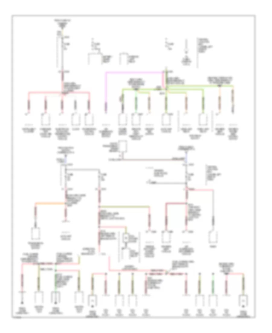
Power Distribution Wiring Diagram (3 of 4) for Ford Expedition 1999
 https://portal-diagnostov.com/license.html
Automotive Electricians Portal FZCO
Automotive Electricians Portal FZCO
https://portal-diagnostov.com/license.html
https://portal-diagnostov.com/license.html
Automotive Electricians Portal FZCO
Automotive Electricians Portal FZCOList of elements for Power Distribution Wiring Diagram (3 of 4) for Ford Expedition 1999:
- (body harn, near breakout to park brake switch) s220
- (diagram 2 of 4) c
- (engine harn, in breakout to fuel injector 7) s162
- (fuel charge harn, right rear of engine compt) s117
- (fuel charge harness, near breakout to noise cap 2) s119
- (fuel charge harness, right rear of engine compt) s117
- (main harn, near breakout to evo module)
- (main harn, near breakout to instrument cluster) s225
- (main harn, near breakout to instrument cluster) s289
- (seat belt retractor harn, near breakout to transfer case) s307
- 5.4l
- Air suspension service switch
- Air suspension/ evo steering module
- Autolamp module
- Battery junction box
- Battery saver relay
- C216
- C243
- C257
- C267
- C268
- C295
- C356
- Central junction box (under left side of dash)
- Clock
- Coil on plug 1
- Coil on plug 2
- Coil on plug 3
- Coil on plug 4
- Coil on plug 5
- Coil on plug 6
- Coil on plug 7
- Coil on plug 8
- Digital transmission range sensor
- Driver's power seat control switch
- Driver's seat module
- Electronic automatic temperature control module
- Expedition w/ 4.6l engine only
- From fuse 103
- From fuse 21 (diagram 2 of 4)
- From ignition switch (diagram 2 of 4)
- Fuse 15a
- Fuse 30a
- Fuse 5a
- Generic electronic module
- Headlamp relay
- Ignition coils 1 & 2
- Ignition coils 3 & 4
- Instrument cluster
- Interior lamp relay
- Memory set switch
- Nca
- Overhead trip computer module
- Park lamp relay
- Passive anti-theft system control module
- Pcm power diode
- Pcm power relay
- Power mirror switch
- Powertrain control module
- Radio
- Radio noise capacitor 1
- Radio noise capacitor 2
- Remote anti- theft personality module
- Rpo relay block 1
- S116 (engine harn, left rear of engine compt)
- S161 (engine harn, in breakout to fuel injector 3)
- S2002 (main harn, near breakout to cental junction box)
- S210 (main body harn, near breakout to central junction box)
- S219
- To fuse 3 (diagram 4 of 4)
- Transmission control switch
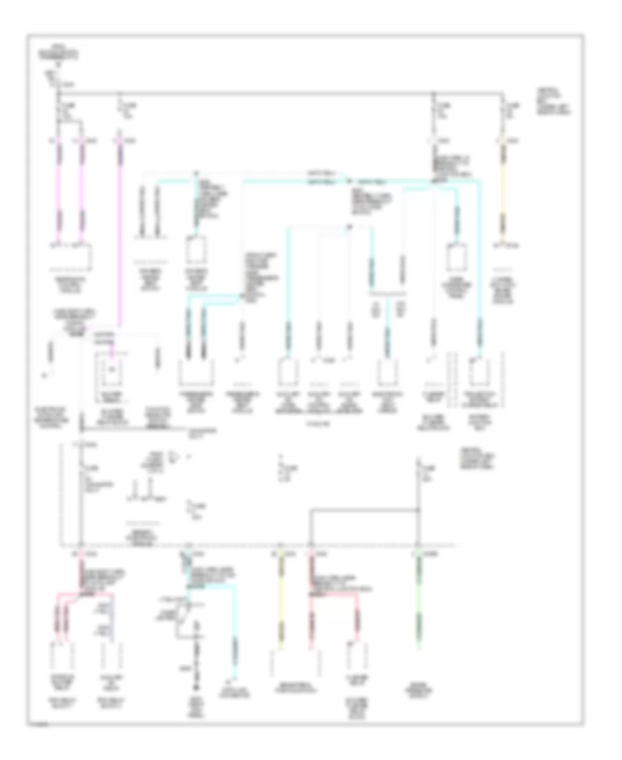
Power Distribution Wiring Diagram (4 of 4) for Ford Expedition 1999
 https://portal-diagnostov.com/license.html
Automotive Electricians Portal FZCO
Automotive Electricians Portal FZCO
https://portal-diagnostov.com/license.html
https://portal-diagnostov.com/license.html
Automotive Electricians Portal FZCO
Automotive Electricians Portal FZCOList of elements for Power Distribution Wiring Diagram (4 of 4) for Ford Expedition 1999:
- (front seat- back pad harness, near passenger's heated seat switch) s328
- (main body harn, near breakout to eatc module) s292
- (main harn, in breakout to central junction box) s228
- (main harn, near breakout to 4wd mode switch) s2005
- (main harn, near breakout to central junction box) s2001
- (navigator only)
- 4 wheel anti-lock brake system module
- Auxiliary a/c blend actautor
- Auxiliary a/c control module
- Auxiliary a/c mode actuator
- Auxiliary a/c relay
- Battery junction box
- Blower relay
- Blower/ flasher relay block
- Brake pedal position switch
- Brake pressure switch
- C146
- C242
- C243
- C267
- C436
- Central junction box (under left side of dash)
- Cigar lighter
- Console blower relay
- Data link connector
- Driver's heated seat module
- Driver's heated seat switch
- Electronic automatic temperature control
- Electronic day/ night mirror
- Flasher relay
- From fuse 4 (diagram 3 of 4)
- From ignition switch (diagram 2 of 4)
- Function selector switch assembly
- Fuse 10a
- Fuse 20a
- Fuse 5a
- Fuse 5a (navigator only)
- G203 (right kick panel)
- Generic electronic module
- Nca
- Passenger's heated seat module
- Passenger's heated seat switch
- Rear integrated control panel
- Restraints control module
- Rpo relay block 1
- Rpo relay block 2
- S205
- S325 (seatbelt harn, near driver's heated seat switch)
- S422 (seatbelt harn, near breakout to a/c mode switch)
- Tan/red
- Trailer tow battery charge relay
- W/ aux a/c
- W/o aux a/c

 Čeština
 Dansk
Dansk Deutsch
 Ελληνικά
 English
 English
 Español
 Suomi
Suomi Français
 Français
 עברית
עברית Hrvatski
 Magyar
 Italiano
 한국어
한국어 Nederlands
 Polski
 Português
 Português
 Română
 Русский
 Slovenčina
 Slovenščina
 Svenska
 Türkçe
 中文 (中国)
