POWER DISTRIBUTION
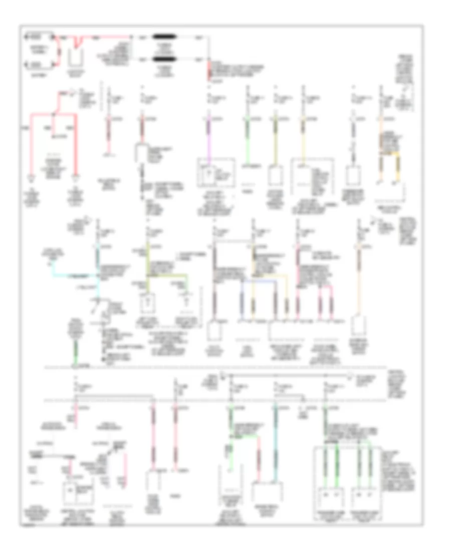
Power Distribution Wiring Diagram (1 of 4) for Ford F550 Super Duty 2004
 https://portal-diagnostov.com/license.html
Automotive Electricians Portal FZCO
Automotive Electricians Portal FZCO
https://portal-diagnostov.com/license.html
https://portal-diagnostov.com/license.html
Automotive Electricians Portal FZCO
Automotive Electricians Portal FZCO
List of elements for Power Distribution Wiring Diagram (1 of 4) for Ford F550 Super Duty 2004:
- (at breakout for auxiliary relay box 4) s103
- (behind left side of dash) g201
- (behind lower left side of dash) central junction box (cjb)
- (diesel)
- (diesel, higher option content) s257 s290
- (except diesel)
- (except diesel) (diesel, higher option content)
- (in back-up light switch to rear light feed harness, at breakout for auxiliary relay box 3) s199
- (near breakout for abs control module) s163
- (near breakout for auxiliary relay box 1) s249
- (near breakout for data link connector) s242
- (near breakout for restraints control module) (w/ electronic shift on the fly) s230
- (near breakout to brake pedal position switch) s214
- (near breakout to main light switch) (w/ power equipment) s272
- (not used)
- A/c clutch relay
- Abs control module
- Adjustable pedal switch
- Automatic transmission
- Auxiliary relay box 1 (behind left center of dash)
- Auxiliary relay box 3 (w/ electronic shift on the fly) (except diesel: at left rear side of engine compt) (diesel: left side of engine compt)
- Auxiliary relay box 4
- Auxiliary relay box 4 (except diesel) auxiliary relay box 5 (diesel) (at left rear side of engine compt)
- Auxiliary relay box 5 (at left rear side of engine compt)
- Battery
- Battery ii (diesel)
- Brake pedal position switch
- C197b
- C202a
- C205a
- C2113b
- C270a
- C270b
- C270d
- C270e
- C270f
- C270g
- C270h
- C270i
- C270j
- C270k
- C270m
- C270p
- C281a
- C281b
- C290a
- Central junction box (cjb) (behind lower left side of dash)
- Clutch pedal position switch
- Data link connector (dlc)
- Daytime running lamps resistor (w/ drl)
- Diesel
- Digital transmission range (dtr) sensor
- Except diesel
- Exterior rear view mirror switch
- Four- wheel drive control module
- Four-wheel drive control module (w/ electronic shift on the fly)
- From a fuse 602 (diagram 1 of 4)
- From fuse 13 (diagram 1 of 4)
- From ignition switch (diagram 3 of 4)
- Front cigar lighter
- Fuel injector control module (ficm) power relay
- Fuse 1 15a
- Fuse 10 10a
- Fuse 11 20a
- Fuse 111 30a
- Fuse 114 30a
- Fuse 12 20a
- Fuse 14 15a
- Fuse 17 15a
- Fuse 18 20a
- Fuse 19 10a
- Fuse 20 10a
- Fuse 31 15a
- Fuse 34 10a
- Fuse 4 20a
- Fuse 5a
- Fuse 6 20a
- Fuse 60a
- Fuse 7 30a
- G201 (behind left side of dash)
- Indicator flasher relay
- Instrument panel power point
- Junction block
- Left turn trailer tow relay
- Main light switch
- Manual transmission
- Multi- function switch
- Nca
- Passenger side front seat adjust switch
- Radio
- Red
- Red k
- Right turn trailer tow relay
- S1000 (in battery output harness, at breakout for junction block on left fender)
- S1002 (diesel) (in battery output harness, near grommet on firewall)
- S275 (near breakout for instrument cluster)
- S290 s257
- Starter motor (lower right rear of engine)
- Starter relay
- To fuse 12 (diagram 1 of 4)
- To fuse 18 (diagram 1 of 4)
- To fuse 35 (diagram 2 of 4)
- To fusible links (diagram 2 of 4)
- Transfer case high to low relay
- Transfer case low to high relay
- Vehicle security module (vsm) (w/ remote keyless entry )
- W/ remote keyless entry
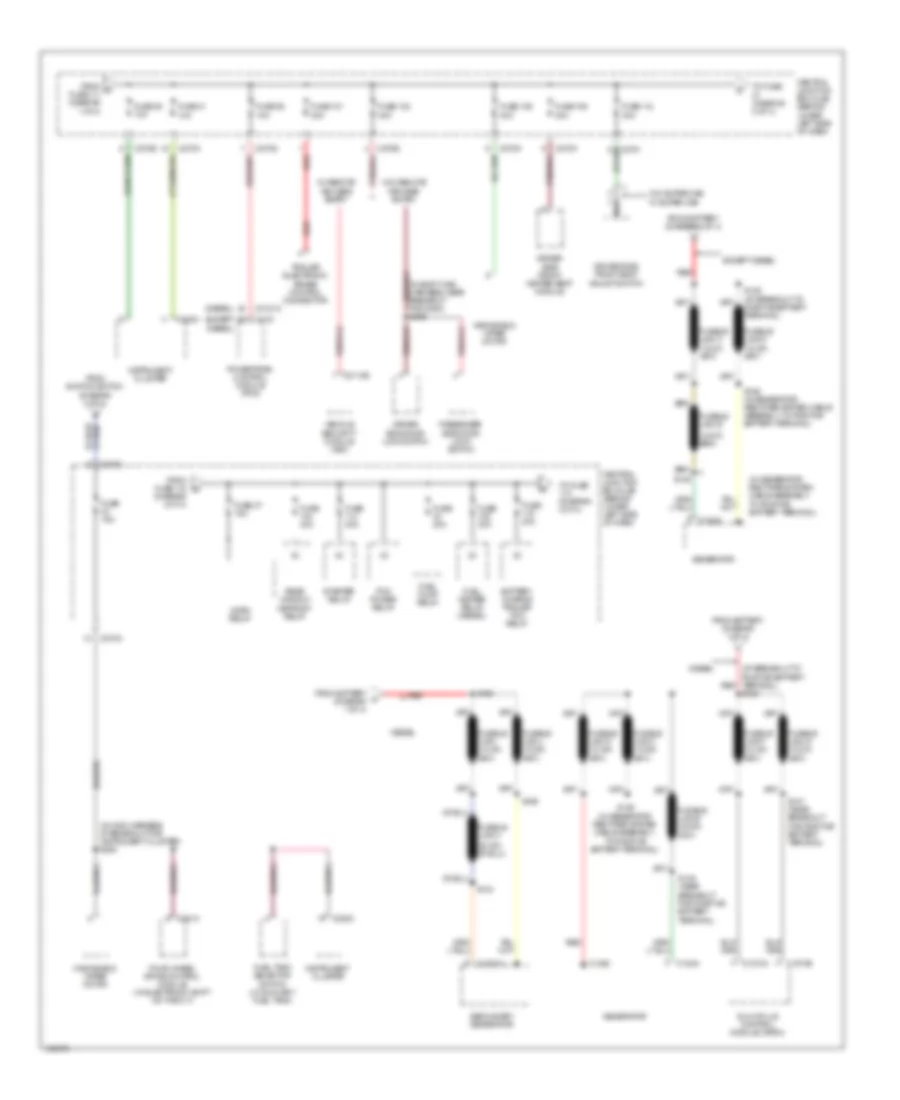
Power Distribution Wiring Diagram (2 of 4) for Ford F550 Super Duty 2004
 https://portal-diagnostov.com/license.html
Automotive Electricians Portal FZCO
Automotive Electricians Portal FZCO
https://portal-diagnostov.com/license.html
https://portal-diagnostov.com/license.html
Automotive Electricians Portal FZCO
Automotive Electricians Portal FZCOList of elements for Power Distribution Wiring Diagram (2 of 4) for Ford F550 Super Duty 2004:
- (at breakout to positive battery terminal) s125
- (diagram 2 of 4)
- (diesel)
- (except diesel)
- (in body main harness, near breakout for g300) s289
- (in generator rectifier system cable assembly, to positive battery terminal)
- (in main harness, at breakout for instrument cluster) s254
- Battery charge trailer tow relay
- C102a
- C102c
- C1251a
- C1273a
- C1273b
- C175
- C2113b
- C220c
- C270a
- C270b
- C270c
- C270e
- C270g
- C270i
- C270k
- C270m
- C281a
- C3181a
- Central junction box (cjb) (behind lower left side of dash)
- Diesel
- Driver side door lock switch
- Driver side front heated seat module
- Driver side front seat adjust switch
- Except diesel
- Four-wheel drive control module (w/ electronic shift on the fly)
- From battery (diagram 1 of 4)
- From c fuse 111 (diagram 1 of 4)
- From fuse 112 d
- From ignition switch (diagram 3 of 4)
- Fuel heater relay (diesel)
- Fuel pump relay
- Fuel tank selector switch (w/ auxiliary fuel tank)
- Fuse 101 30a
- Fuse 102 30a
- Fuse 106 30a
- Fuse 109 30a
- Fuse 112 30a
- Fuse 15a
- Fuse 20a
- Fuse 30a
- Fuse 35 10a
- Fuse 36 10a
- Fuse 37 15a
- Fuse 40a
- Fuse 41 10a
- Fusible link e
- Fusible link h
- Generator
- Glow plug control module (gpcm)
- Horn relay
- Instrument cluster
- Nca
- Passenger side door lock switch
- Pcm power relay
- Powertrain control module (pcm)
- Rear window defrost relay
- Red
- S125 (at breakout to positive battery terminal)
- S126 (in generator rectifier system cable assembly, to positive battery terminal)
- S143
- S147 (near breakout for positive battery terminal)
- S149
- S149 (near breakout for positive battery terminal)
- S165
- S166
- Secondary generator
- Starter relay
- To fuse (diagram 2 of 4)
- To fuse (diagram 3 of 4)
- Trailer electronic brake control connector
- Vehicle security module (vsm)
- W/ remote keyless entry
- W/o remote keyless entry
- W/o super cab w/ super cab
- Windshield wiper motor
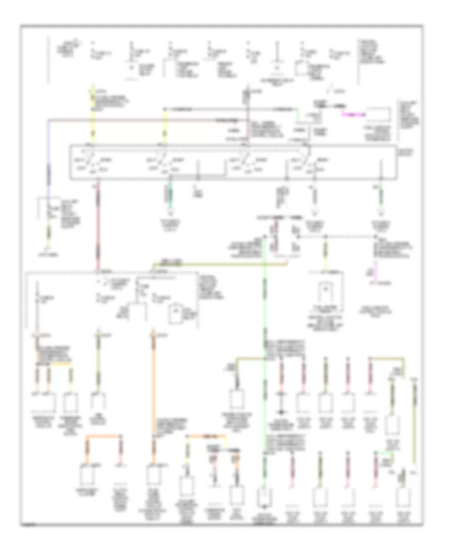
Power Distribution Wiring Diagram (3 of 4) for Ford F550 Super Duty 2004
 https://portal-diagnostov.com/license.html
Automotive Electricians Portal FZCO
Automotive Electricians Portal FZCO
https://portal-diagnostov.com/license.html
https://portal-diagnostov.com/license.html
Automotive Electricians Portal FZCO
Automotive Electricians Portal FZCOList of elements for Power Distribution Wiring Diagram (3 of 4) for Ford F550 Super Duty 2004:
- (5.4l: near breakout for fuel injector 3) (6.8l: near breakout for fuel injector 5) s135
- (5.4l: near breakout for fuel injector 6) (6.8l: near breakout for fuel injector 9) s130
- (diesel)
- (in main harness, near breakout for instrument cluster) s271
- (in main harness, near breakout for restraints control module) s202
- (in main harness, near breakout to ignition switch) s210
- (not used)
- (w/ electronic shift on the fly)
- 5.4l
- 6.8l
- Abs control module
- Acc
- Accessory delay relay
- Auxiliary powertrain control module (apcm) (diesel)
- Auxiliary relay box 5 (at left rear side of engine compt)
- Blower motor relay
- C1388c
- C220c
- C270a
- C270c
- C270e
- C270f
- C281a
- Central junction box (cjb) (behind lower left side of dash)
- Clutch pedal position switch (diesel w/ m/t)
- Coil on plug (cop) 1
- Coil on plug (cop) 10
- Coil on plug (cop) 2
- Coil on plug (cop) 3
- Coil on plug (cop) 4
- Coil on plug (cop) 5
- Coil on plug (cop) 6
- Coil on plug (cop) 7
- Coil on plug (cop) 8
- Coil on plug (cop) 9 (6.8l)
- Diesel
- Except diesel
- Fog lamp relay
- Four- wheel drive control module
- From e fuse 115 (diagram 2 of 4)
- Fuel heater relay
- Fuel injector control module (ficm)
- Fuel injector control module (ficm) power relay
- Fuse 103 50a
- Fuse 107 40a
- Fuse 10a
- Fuse 110 50a
- Fuse 20a
- Fuse 25 10a
- Fuse 26 10a
- Fuse 30a
- Fuse 38 20a
- Fuse 39 15a
- Fuse 45 10a
- Fuse 8 15a
- Heated positive crankcase ventilation (pcv) element (6.8l)
- Ignition switch
- Ignition transformer capacitor 1
- Ignition transformer capacitor 2
- Instrument cluster
- Lock
- Nca
- Off
- Overdrive cancel switch
- Parking lamp trailer tow relay
- Passenger air bag deactivation (pad) switch
- Pcm power relay
- Restraints control module
- Reversing lamp trailer tow relay
- Reversing lamps relay (diesel)
- Run
- S224 (in main harness, near breakout to brake pedal position switch)
- S231 (near breakout for restraints control module)
- S258 (in main harness, near breakout to brake pedal position switch)
- Sta
- Start
- To fuse 27 (diagram 4 of 4)
- To fuse 31 (diagram 1 of 4)
- To fuse 33 (diagram 2 of 4)
- Tow/ haul switch
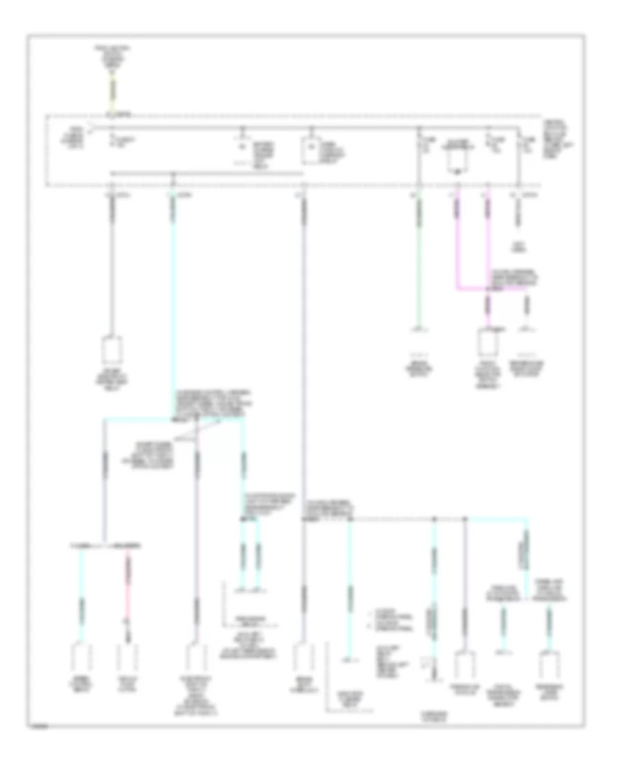
Power Distribution Wiring Diagram (4 of 4) for Ford F550 Super Duty 2004
 https://portal-diagnostov.com/license.html
Automotive Electricians Portal FZCO
Automotive Electricians Portal FZCO
https://portal-diagnostov.com/license.html
https://portal-diagnostov.com/license.html
Automotive Electricians Portal FZCO
Automotive Electricians Portal FZCOList of elements for Power Distribution Wiring Diagram (4 of 4) for Ford F550 Super Duty 2004:
- (in daytime running light kit harness, near breakout for c1047) s198
- (in engine control harness, near breakout for g100) (except diesel w/ electronic shift on the fly or diesel w/ higher option content) s124
- (in main harness, near breakout to sunload sensor) s206
- (in main harness, near breakout to sunload sensor) s235
- (not used)
- 5.4l/6.8l
- 6.0l diesel
- Auxiliary relay box 1 (behind left center of dash)
- Auxiliary relay box 2 (w/ drl) (at left rear side of engine compartment)
- Battery charge trailer tow relay
- Blower motor relay
- Brake pressure switch
- Brake shift interlock
- C270a
- C270c
- C270h
- C294a
- Central junction box (cjb) (behind lower left side of dash)
- Diesel and gasoline w/ manual transmission
- Digital transmission range (dtr) sensor
- Driver side front heated seat relay
- Electronic shift on the fly (esof) solenoid (w/ electronic shift on the fly)
- Except diesel w/ electronic shift on the fly or diesel w/ higher option content
- From fuse 25 (diagram 3 of 4)
- From ignition switch (diagram 3 of 4)
- Front function selector switch assembly
- Fuse 10a
- Fuse 27 15a
- Fuse 2a
- Gasoline w/ automatic transmission
- Indicator flasher relay
- Nca
- Overhead console
- Park brake relay
- Parking aid module
- Rear window defrost relay
- Reversing lamps switch
- Speed control servo
- Temperature blend door actuator
- Vacuum pump motor
- W/ roof opening panel
- W/o roof opening panel

 Čeština
 Dansk
Dansk Deutsch
 Ελληνικά
 English
 English
 Español
 Suomi
Suomi Français
 Français
 עברית
עברית Hrvatski
 Magyar
 Italiano
 한국어
한국어 Nederlands
 Polski
 Português
 Português
 Română
 Русский
 Slovenčina
 Slovenščina
 Svenska
 Türkçe
 中文 (中国)
