POWER DISTRIBUTION
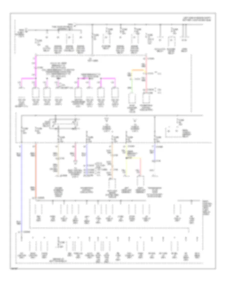
Power Distribution Wiring Diagram, Except Hybrid (1 of 7) for Ford Fusion S 2013
 https://portal-diagnostov.com/license.html
Automotive Electricians Portal FZCO
Automotive Electricians Portal FZCO
https://portal-diagnostov.com/license.html
https://portal-diagnostov.com/license.html
Automotive Electricians Portal FZCO
Automotive Electricians Portal FZCO
List of elements for Power Distribution Wiring Diagram, Except Hybrid (1 of 7) for Ford Fusion S 2013:
- (in breakout to right front windshield wiper motor)
- (left side of engine compt) battery junction box (bjb)
- (near breakout to c134)
- (near breakout to g101) s112
- (near breakout to g101) s113
- (near breakout to knock sensor 2) s147
- (not used)
- (w/ auto start/ stop system) s140
- 1.6l turbo
- 1.6l turbo & 2.5l
- 1.6l turbo 2.0l & 2.0l flex fuel
- 2.0l & 2.0l flex fuel
- 2.0l & 2.0l flex fuel 1.6l turbo
- 2.0l flex fuel, 2.0l & 3.7l
- 2.5l
- 3.7l
- Active grille shutter
- Air conditioning (a/c) compressor control solenoid
- Battery
- Battery monitoring sensor (w/ auto start/stop system)
- C1010
- C1026
- C102c
- C1035a
- C1035c
- C1232b
- C134
- C1381b
- C146
- C1463a
- C1551b
- C1558c
- C1617a
- C1617b
- C1617c
- C1617e
- C1617f
- C1617h
- C1716a
- C1716b
- C1716c
- C1716e
- C1716f
- C1716h
- C175b
- Egr stepper motor (2.5l)
- Electric motor coolant pump (w/ auto start/ stop system)
- Engine coolant valve (1.6l turbo)
- Engine cooling bypass solenoid (1.6l turbo)
- Evap canister vent valve (2.5l & 1.6l turbo)
- Evap purge valve (2.0l flex fuel, 2.0l & 1.6l turbo)
- Evaporative emission (evap) purge valve (3.7l)
- Evaporative emission (evap) purge valve (except 3.7l)
- Fuel pump (fp) relay
- Fuse 10a
- Fuse 15a
- Fuse 20a
- Generator
- Generator current sensor
- Heated oxygen sensor (ho2s) 12 (3.7l)
- Heated oxygen sensor (ho2s) 12 (except 3.7l)
- Heated oxygen sensor (ho2s) 22 (3.7l)
- High current battery junction box (bjb) (left side of engine compt)
- Mass air flow intake air temperature (maf/iat) sensor (2.5l & 3.7l)
- Mega fuse 125a
- Mega fuse 275a
- Mega fuse 50a
- Mega fuse 70a
- Nca
- Pcm power relay
- Power steering control module (pscm)
- Powertrain control module (pcm)
- Red
- S110
- S135 (1.6l turbo)
- Starter motor
- To body control module (bcm) (diagram 4 of 7)
- To body control module (bcm) (diagram 6 of 7)
- To dc to dc converter control module (diagram 7 of 7)
- To fuse 11 (diagram 2 of 7)
- To fuse 37 (diagram 2 of 7)
- Turbo- charger (tc) wastegate regulating solenoid valve (1.6l turbo, 2.0l & 2.0l flex fuel)
- Turbo- charger bypass valve (tcby) (1.6l turbo, 2.0l flex fuel & 2.0l)
- Universal heated oxygen sensor (ho2s) 11 (1.6l turbo, 2.0l & 2.0l flex fuel)
- Universal heated oxygen sensor (ho2s) 11 (3.7l)
- Universal heated oxygen sensor (ho2s) 11 (except 3.7l)
- Universal heated oxygen sensor (ho2s) 21 (3.7l)
- Variable camshaft timing 11 (vct11) solenoid (3.7l)
- Variable camshaft timing 11 (vct11) solenoid (except 3.7l)
- Variable camshaft timing 12 (vct12) solenoid (1.6l turbo, 2.0l & 2.0l flex fuel)
- Variable camshaft timing 12 (vct12) solenoid (3.7l)
- Variable camshaft timing 21 (vct21) solenoid (3.7l)
- Variable camshaft timing 22 (vct22) solenoid (3.7l)
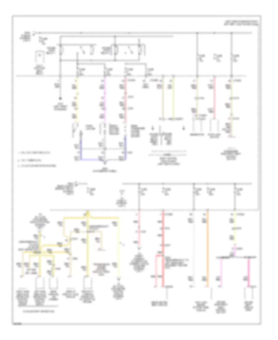
Power Distribution Wiring Diagram, Except Hybrid (2 of 7) for Ford Fusion S 2013
 https://portal-diagnostov.com/license.html
Automotive Electricians Portal FZCO
Automotive Electricians Portal FZCO
https://portal-diagnostov.com/license.html
https://portal-diagnostov.com/license.html
Automotive Electricians Portal FZCO
Automotive Electricians Portal FZCO
List of elements for Power Distribution Wiring Diagram, Except Hybrid (2 of 7) for Ford Fusion S 2013:
- (2.0l & 1.6l: near breakout to coil on plug 2)
- (2.5l: near breakout to ignition transformer capacitor) (3.7l: near breakout to coil on plug 2) s144
- (left side of engine compt) battery junction box (bjb)
- (near breakout to coil on plug 56) s154
- (not used)
- 2.0l & 2.0l flex fuel 1.6l turbo
- 2.5l
- 3.7l
- A/c clutch relay
- Anti-lock brake system (abs) module
- Auto park ind (fet)
- Back lighting (fet)
- Blower motor relay
- Body control module (bcm) (left end of dash)
- Bsi (fet)
- C1010
- C1026
- C1035a
- C1035b
- C1232b
- C1381b
- C146
- C1463b
- C1551b
- C175b
- C192
- C2280b
- Coil on plug (cop) 1
- Coil on plug (cop) 2
- Coil on plug (cop) 3
- Coil on plug (cop) 4 (3.7l)
- Coil on plug (cop) 4 (except 3.7l)
- Coil on plug (cop) 5 (3.7l)
- Coil on plug (cop) 6 (3.7l)
- Demand lp/ batt save relay
- Engine cooling fan high relay
- Engine cooling fan low relay
- Engine cooling fan relay
- Evap canister vent valve
- Except 2.5l
- From e fuel pump (fp) relay (diagram 1 of 7)
- From fuse 7 (diagram 1 of 7)
- Fuse (2.5l & 3.7l) 10a
- Fuse 10a
- Fuse 15a
- Fuse 30a
- Fuse 40a
- Fuse 50a
- Fuse 5a
- Horn relay
- Ignition transformer capacitor (2.5l)
- Int lighting (fet)
- Left headlamp assembly
- Left hi beam (fet)
- Lf drl lp (fet)
- Lf fog lp (fet)
- Lf low beam (fet)
- Lf pos lp (fet)
- Lf turn lp (fet)
- Lr stop pos lps (fet)
- Lr turn lp (fet)
- Park aid ind (fet)
- Park lps (fet)
- Pcm wake up (fet)
- Power steering control module (pscm)
- Powertrain control module (pcm)
- Rear window defrost relay
- Rev lps (fet)
- Rf drl lp (fet)
- Rf fog lp (fet)
- Rf hi beam (fet)
- Rf low beam (fet)
- Rf pos lp (fet)
- Rf turn lamp (fet)
- Rf turn lp (fet)
- Right headlamp assembly
- Rr stop pos lps (fet)
- Rr turn lp (fet)
- Run/ start relay
- Starter relay
- Stop/ chmsl (fet)
- To body control module (bcm) (diagram 6 of 7)
- To fuse 23 (diagram 3 of 7)
- To fuse 53 (diagram 3 of 7)
- Transmission fluid pump (w/ auto start/ stop system)
- White light (fet)
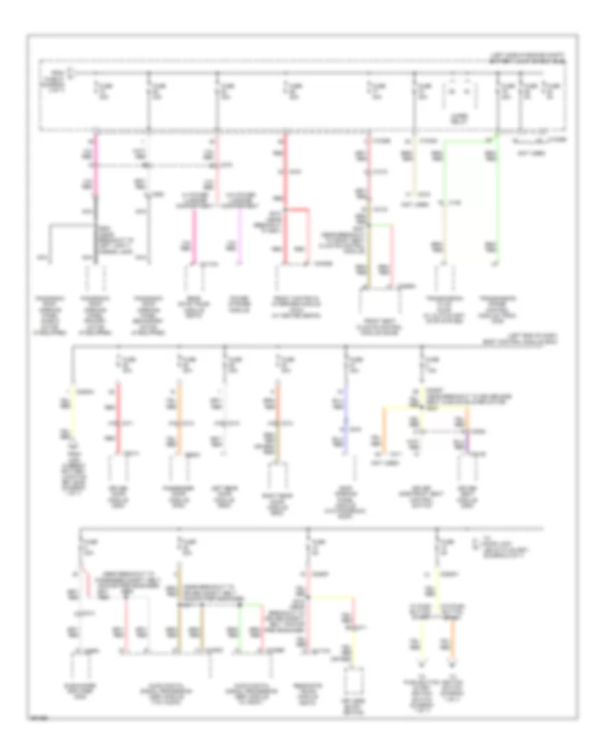
Power Distribution Wiring Diagram, Except Hybrid (3 of 7) for Ford Fusion S 2013
 https://portal-diagnostov.com/license.html
Automotive Electricians Portal FZCO
Automotive Electricians Portal FZCO
https://portal-diagnostov.com/license.html
https://portal-diagnostov.com/license.html
Automotive Electricians Portal FZCO
Automotive Electricians Portal FZCO
List of elements for Power Distribution Wiring Diagram, Except Hybrid (3 of 7) for Ford Fusion S 2013:
- (left end of dash)
- (left front of engine )
- (left side of engine compt) battery junction box (bjb)
- (near breakout to c275) (w/ blind spot detection) s308
- (near breakout to g101) s114
- (not used)
- (w/ blind spot detection)
- 1.6 l turbo & 2.5l
- 2.0l, 2.0l flex fuel & 3.7l
- Anti-lock brake system (abs) module
- Body control module (bcm)
- C1010
- C102a
- C1035a
- C1035b
- C129
- C146
- C1558a b
- C215
- C219
- C2280c
- C263
- C3047
- C3053
- C3133
- C3304b
- C340
- C341a
- C406
- C922
- Cigar lighter
- Driver seat module (dsm)
- Driver side front seat control switch
- From fuse 68 (diagram 2 of 7)
- From rear window defrost relay (diagram 2 of 7)
- Front power outlet socket
- Fuse 10a
- Fuse 15a
- Fuse 20a
- Fuse 30a
- Fuse 40a
- Fuse 60a
- G101
- G200 (in steering wheel)
- Generator
- Head up display (hud) module
- Left side obstacle detection control module (sod-l)
- Micro
- Multi contour seat relay
- Passenger side front seat control switch
- Power point relay 1
- Power point relay 2
- Power point relay reset (fet)
- Power point relay set (fet)
- Proximity warning radar unit (w/ adaptive cruise)
- Rear heated seat module
- Rear parking aid camera
- Rear passenger power outlet socket
- Red
- Right side obstacle detection control module (sod-r)
- S302 (near breakout to left rear seat backrest heater mat)
- Stop lamp switch
- To dc to dc converter control module (diagram 7 of 7)
- To dc to dc converter module control (diagram 7 of 7)
- To direct current/ alternating current (dc/ac) inverter (diagram 7 of 7)
- To fuse 72 (diagram 4 of 7)
- Transmission range control module (trcm) (mkz)
- W/ auto start/stop system
- W/ memory
- W/o memory
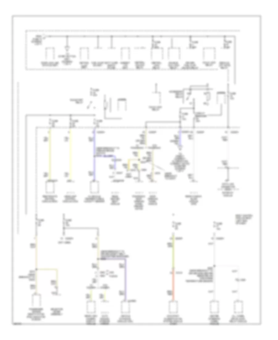
Power Distribution Wiring Diagram, Except Hybrid (4 of 7) for Ford Fusion S 2013
 https://portal-diagnostov.com/license.html
Automotive Electricians Portal FZCO
Automotive Electricians Portal FZCO
https://portal-diagnostov.com/license.html
https://portal-diagnostov.com/license.html
Automotive Electricians Portal FZCO
Automotive Electricians Portal FZCO
List of elements for Power Distribution Wiring Diagram, Except Hybrid (4 of 7) for Ford Fusion S 2013:
- (left end of dash) body control module (bcm)
- (left side of engine compt) battery junction box (bjb)
- (near breakout to driver side seat cushion blower motor) s227
- (near breakout to passenger safety belt anchor pretensioner) s306
- (not used)
- A16
- Audio digital signal processing (dsp) module (thx audio)
- Audio digital signal processing (dsp) module (w/ sony)
- B3 c311
- C1010
- C1035a
- C1035b
- C146
- C214
- C215
- C219
- C2280a
- C2280f
- C2280h
- C2402b
- C3052
- C311
- C312
- C313
- C3133
- C314
- C3265a
- C341b
- C4174a
- C4326b
- C4452c
- C466a
- C501a
- C652a
- C919
- C925
- Driver door module (ddm)
- Driver safety belt anchor pretensioner)
- Driver seat module (dsm)
- Driver side front seat control switch
- From fuse 81 (diagram 3 of 7)
- From high current battery junction box (bjb) (diagram 1 of 7)
- Front controls interface module (fcim) (w/ heated seats)
- Front seat climate control module (scme)
- Fuse 20a
- Fuse 30a
- Fuse 40a
- Fuse 5a
- Fuse 7.5a
- Keyless entry keypad
- Left rear door module (rdm)
- Nca
- Panoramic roof opening panel primary motor (if equipped)
- Panoramic roof opening panel secondary motor (if equipped)
- Panoramic roof opening panel shield motor (if equipped)
- Passenger door module (pdm)
- Power striker module
- Rear gate trunk module (rgtm)
- Red
- Right rear door module (rdm)
- Roof opening panel module (w/o panoromic roof)
- S210 (near breakout to g201)
- S318 (near breakout to driver safety belt anchor pretensioner)
- S327 (near breakout to front seat climate control module)
- S411
- S902 (near breakout to left vanity mirror lamp)
- Subwoofer amplifier (mkz)
- To door lock led status (fet) (diagram 5 of 7)
- To ignition switch (diagram 7 of 7)
- To push button start ignition switch (diagram 7 of 7)
- Transmission fluid pump (w/ auto start/ stop system)
- Transmission range control module (trcm) (mkz)
- W/ power luggage compartment
- W/ push button start
- W/o power luggage compartment
- W/o push button start
- Wiper relay
Power Distribution Wiring Diagram, Except Hybrid (5 of 7) for Ford Fusion S 2013
 https://portal-diagnostov.com/license.html
Automotive Electricians Portal FZCO
Automotive Electricians Portal FZCO
https://portal-diagnostov.com/license.html
https://portal-diagnostov.com/license.html
Automotive Electricians Portal FZCO
Automotive Electricians Portal FZCO
List of elements for Power Distribution Wiring Diagram, Except Hybrid (5 of 7) for Ford Fusion S 2013:
- (near breakout to c3047)
- (near breakout to driver safety belt anchor pretensioner) s323
- (near breakout to g202)
- (near breakout to parking brake switch) s219
- (not used)
- Accessory delay relay
- All wheel drive (awd) relay module
- Ambient ltg (fet)
- Auto dimming interior mirror
- Batt curr sns 5v fd (hb)
- Body control module (bcm) (left end of dash)
- C2280f
- C2280h
- C248
- C263
- C3047
- C310a
- C3133
- C3304b
- C4396c
- C900
- C919
- C925
- Central lock relay
- Central unlock relay
- Child lock relay
- Circuit breaker 30a
- Data link c0nnector (dlc)
- Decklid/ lift gate relay
- Door lock led status (fet)
- Double/ aux lock relay
- Driver/ fuel flap unlock relay
- From k fuse 18 (diagram 4 of 7)
- Fuel pump on (fet)
- Fuse 10a
- Fuse 15a
- Fuse 20a
- Fuse 30a
- Fuse 5a
- Fusion
- Gateway module
- Headlamp control module (hcm)
- Heated steering wheel module
- In vehicle temperature & humidity sensor
- Keypad illum (fet)
- Micro
- Mkz
- Nca
- Occupant classification system module (ocsm)
- Panoramic roof opening panel primary motor
- Passenger air bag deactivation (pad) indicator (fusion)
- Rear heated seat module
- Rear view camera display module
- Rear window blind module (mkz)
- Restraints control module (rcm)
- Roof opening panel module
- Run/start relay
- S212
- S220 (near breakout to driver side center register air discharge temperature sensor)
- S233
- Selector lever assembly
- To direct current/ alternating current (dc/ac) inverter (diagram 7 of 7)
- To start button (fet) (diagram 7 of 7)
- Vehicle dynamics module (vdm)
- W/ camera
- W/ panoramic
- W/o camera
- W/o panoramic
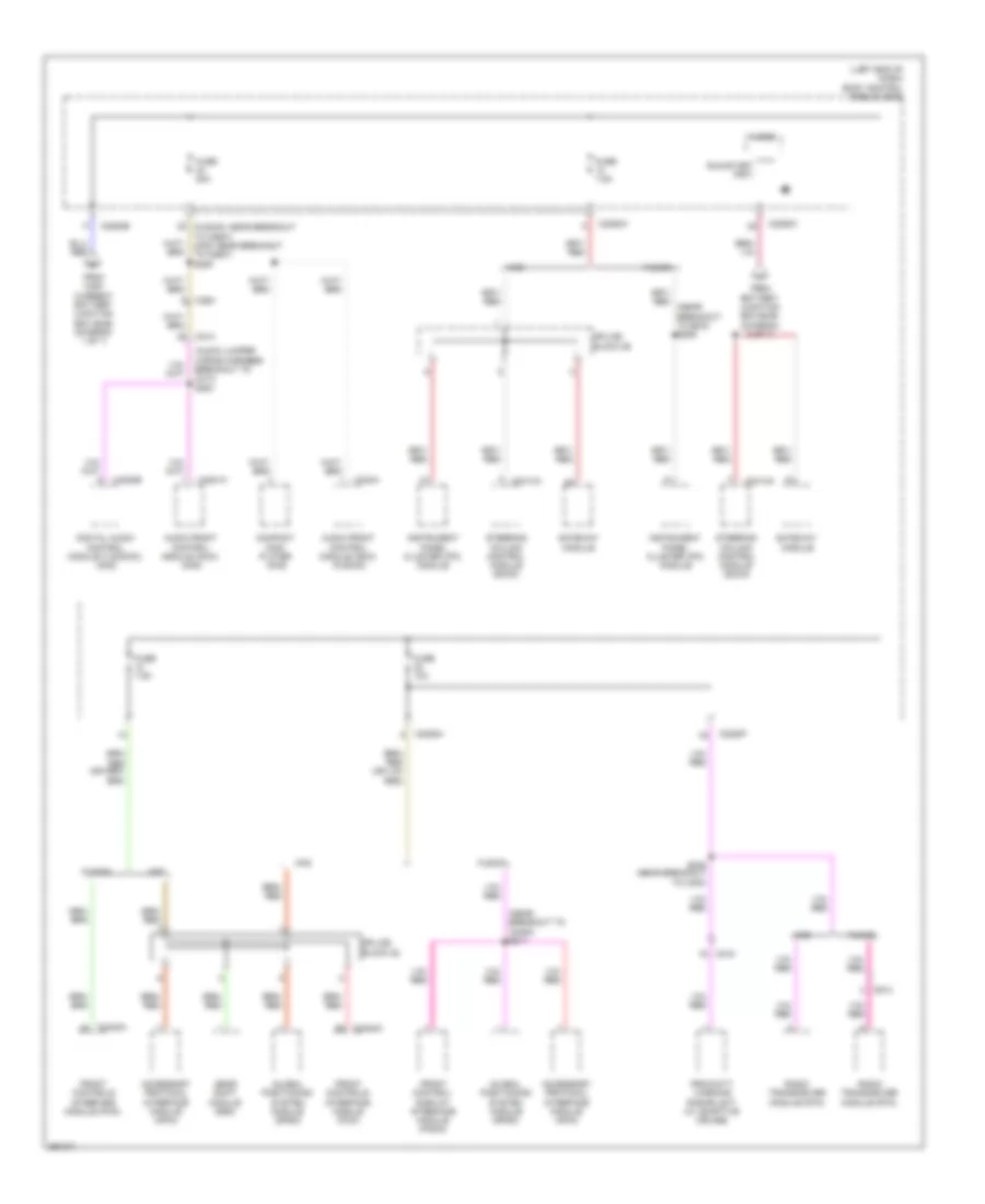
Power Distribution Wiring Diagram, Except Hybrid (6 of 7) for Ford Fusion S 2013
 https://portal-diagnostov.com/license.html
Automotive Electricians Portal FZCO
Automotive Electricians Portal FZCO
https://portal-diagnostov.com/license.html
https://portal-diagnostov.com/license.html
Automotive Electricians Portal FZCO
Automotive Electricians Portal FZCO
List of elements for Power Distribution Wiring Diagram, Except Hybrid (6 of 7) for Ford Fusion S 2013:
- (audio jumper wiring harness breakout to c214) s200
- (fusion: near breakout to c2607) (mkz: near breakout to c2607) s209
- (left end of dash) body control module (bcm)
- (near breakout to bcm) s206
- (near breakout to c2480) s211
- Accessory protocol interface module (apim)
- Audio front control module (acim) (fusion)
- Audio front control module (acim) (mkz)
- C214
- C215
- C2280b
- C2280c
- C2280f
- C2280h
- C2402a
- C240a
- C2414a
- C263
- C4820b
- C4821a
- C913
- Compact disc player (mkz)
- Digital audio control module c (dacmc) (mkz)
- From battery junction box (bjb) (diagram 2 of 7)
- From high current battery junction box (bjb) (diagram 1 of 7)
- Front control/ display interface module (fcdim)
- Front controls interface module (fcim)
- Fuse 10a
- Fuse 20a
- Fuse 7.5a
- Fusion
- Gateway module
- Gear shift module (gsm)
- Global positioning system module (gpsm)
- Instrument panel cluster (ipc) module
- Micro
- Mkz
- Proximity warning radar unit (w/ adaptive cruise)
- Radio transceiver module (rtm)
- Run/start (fet)
- S305 (near breakout to c300)
- Splice block 22
- Splice block 26
- Steering column control module (sccm)
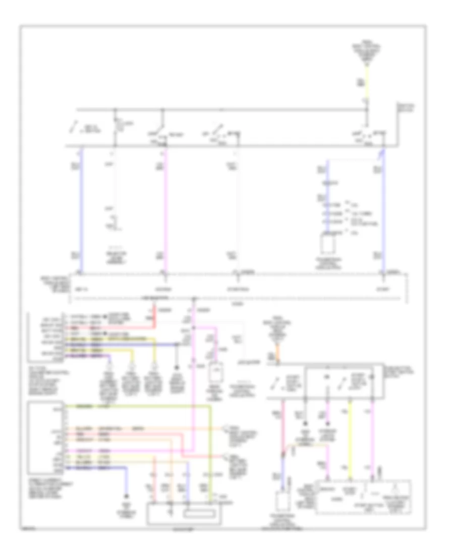
Power Distribution Wiring Diagram, Except Hybrid (7 of 7) for Ford Fusion S 2013
 https://portal-diagnostov.com/license.html
Automotive Electricians Portal FZCO
Automotive Electricians Portal FZCO
https://portal-diagnostov.com/license.html
https://portal-diagnostov.com/license.html
Automotive Electricians Portal FZCO
Automotive Electricians Portal FZCO
List of elements for Power Distribution Wiring Diagram, Except Hybrid (7 of 7) for Ford Fusion S 2013:
- 1.6l turbo
- 2.0l & 2.0l flex fuel
- 2.5l
- 3.5l
- Ac outlet
- Ac-a
- Ac-b
- Acc
- Acc/run
- Batt pwr
- Battery junction box (bjb) (diagram 3 of 7)
- Body control module (bcm) (left end of dash)
- C1232b
- C1381b
- C1551b
- C175b
- C219
- C2280b
- C2280d
- C2280g
- C2280h
- C248
- C340
- C406
- Cbb23
- Ce170
- Computer data lines system
- Dc to dc converter control module (w/ auto start/ stop system) (right rear of engine compt)
- Direct current/ alternating current (dc/ac) inverter (behind lower center of dash)
- Eng st sig
- Eng sw
- From
- From battery junction box (bjb) (diagram 3 of 7)
- From body control module (bcm) (diagram 4 of 7)
- From body control module (bcm) (diagram 5 of 7)
- From high current battery junction box (bjb) (diagram 1 of 7)
- From keypad illum (fet) (diagram 5 of 7)
- Fusion
- G103 (right rear of engine compt)
- G200 (in steering wheel)
- Gd214
- Gd241
- Gnd
- Hs1 can +
- Hs1 can -
- Hya01
- Hya02
- Ign sw sig
- Ignition switch
- Inn sw sig
- Interior lights system
- Key in
- Key in ignition
- Led+
- Led-
- Lin
- Lin 01
- Lock
- Lya03
- Micro
- Mkz
- Nca
- Off
- Powertrain control module (pcm)
- Powertrain control module (pcm) (2.0l & 2.0l flex fuel)
- Push button start ignition switch
- Pwr
- Rear parking aid camera
- Red
- Run
- Rya03
- S310
- Sb101
- Sbb81
- Sbf03
- Sbp23
- Selector lever assembly
- Start
- Start button (fet)
- Start/ stop
- Start/ stop 1 (active high)
- Start/ stop 2 (active low)
- Start/run
- Vdb04
- Vdb05
- Vdn04
- Vqm bus pwr
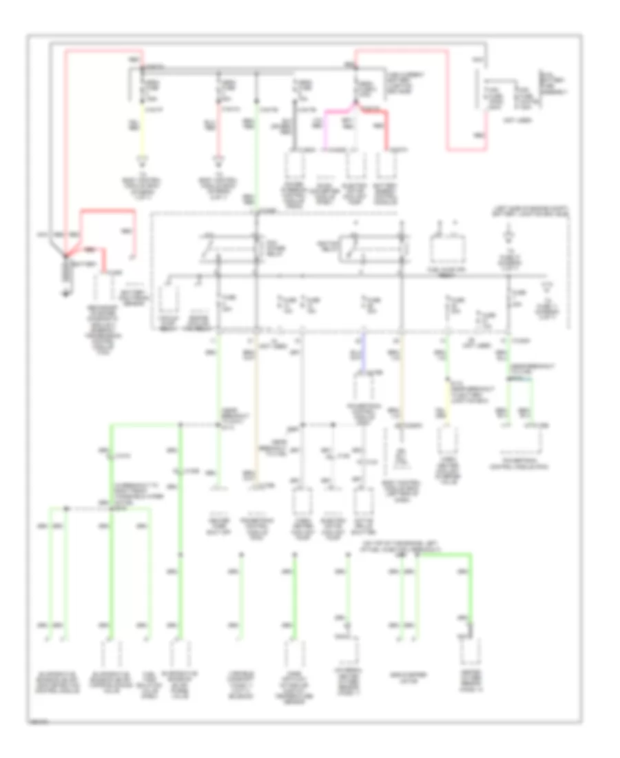
Power Distribution Wiring Diagram, Hybrid (1 of 7) for Ford Fusion S 2013
 https://portal-diagnostov.com/license.html
Automotive Electricians Portal FZCO
Automotive Electricians Portal FZCO
https://portal-diagnostov.com/license.html
https://portal-diagnostov.com/license.html
Automotive Electricians Portal FZCO
Automotive Electricians Portal FZCO
List of elements for Power Distribution Wiring Diagram, Hybrid (1 of 7) for Ford Fusion S 2013:
- (left side of engine compt) battery junction box (bjb)
- (near breakout to c192)
- (near breakout to c192) s112
- (near breakout to g101) s113
- (not used)
- (on top of the engine, left of fuel injector 4 breakout) s147
- Active grille shutter
- Battery
- Battery energy control m0odule
- Battery monitoring sensor
- Body control module (bcm) (left end of dash)
- C1010
- C1026
- C1035a
- C1035c
- C134
- C146
- C1463a
- C148g
- C1617a
- C1617b
- C1617e
- C1617f
- C1617h
- C1617k
- C175b
- C2280c
- C4237a
- C4453d
- Cabin heater coolant diverter valve
- Cabin heater coolant pump
- Dc/dc converter module (phev)
- Dual battery fuse assembly
- Egr stepper motor
- Electric motor coolant pump
- Engine cooling fan relay
- Evaporative emission (evap) leak detection control module
- Evaporative emission (evap) purge valve
- Evaporative emission (evap) vapor blocking valve
- Fuel pump (fp) relay
- Fuel tank isolation valve (phev)
- Fuse 10a
- Fuse 15a
- Fuse 20a
- Fuse 30a
- Heated oxygen sensor (ho2s) 12
- Heater core shut off
- High current battery junction box (bjb)
- Ign rly ctrl
- Ignition relay
- Mass air flow/ intake air (maf/iat) temperature sensor
- Mega fuse 125a
- Mega fuse 50a
- Mega fuse 70a
- Mega fuse 8 275a
- Midi fuse (pink) 200a
- Midi fuse (white) 120a
- Nca
- Pcm power relay
- Power steering control module (pscm)
- Powertrain control module (pcm)
- Red
- S110
- S115 (near breakout to battery junction box)
- S315
- Secondary on board diagnostic module c (sobdmc)/ transmission control module (tcm)
- To body control module (bcm) (diagram 4 of 7)
- To body control module (bcm) (diagram 6 of 7)
- To fuse 11 (diagram 2 of 7)
- To fuse 37 (diagram 2 of 7)
- Universal heated oxygen sensor (ho2s) 11
- Vacuum pump relay
- Variable camshaft timing 11 (vct11) solenoid
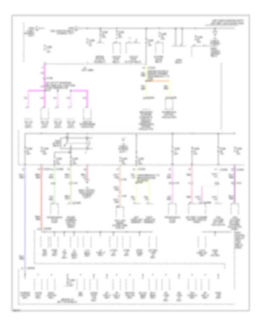
Power Distribution Wiring Diagram, Hybrid (2 of 7) for Ford Fusion S 2013
 https://portal-diagnostov.com/license.html
Automotive Electricians Portal FZCO
Automotive Electricians Portal FZCO
https://portal-diagnostov.com/license.html
https://portal-diagnostov.com/license.html
Automotive Electricians Portal FZCO
Automotive Electricians Portal FZCO
List of elements for Power Distribution Wiring Diagram, Hybrid (2 of 7) for Ford Fusion S 2013:
- (engine controls sensor harness, near breakout to c192) s141
- (left side of engine compt) battery junction box (bjb)
- (not used)
- Anti-lock brake system (abs) module
- Auto park ind (fet)
- Back lighting (fet)
- Battery charger control module (phev)
- Blower motor relay
- Body control module (bcm) (left end of dash)
- Bsi (fet)
- C1026
- C1035a
- C1035b
- C1458a
- C146
- C1463b
- C175b
- C192
- C215
- C2280b
- C4455b
- Coil on plug (cop) 1
- Coil on plug (cop) 2
- Coil on plug (cop) 3
- Coil on plug (cop) 4
- Demand lp/ batt save relay
- Engine cooling fan relay
- From d fuel pump (fp) relay (diagram 1 of 7)
- From fuse 7 (diagram 1 of 7)
- Fuse 10a
- Fuse 15a
- Fuse 20a
- Fuse 30a
- Fuse 40a
- Fuse 50a
- Fuse 5a
- High voltage battery charger cooling fan (phev)
- High voltage battery cooling fan
- Horn relay
- Ignition transformer capacitor
- Interior lighting (fet)
- Left headlamp assembly
- Lf drl lp (fet)
- Lf fog lp (fet)
- Lf hi beam (fet)
- Lf low beam (fet)
- Lf pos lp (fet)
- Lf turn lp (fet)
- Lr pos stop lps (fet)
- Lr turn turn lp (fet)
- Park aid ind (fet)
- Park lps (fet)
- Pcm wake up (fet)
- Power steering control module (pscm)
- Powertrain control module (pcm)
- Rear window defrost relay
- Red
- Rev lps (fet)
- Rf drl lp (fet)
- Rf fog lp (fet)
- Rf hi beam (fet)
- Rf low beam (fet)
- Rf pos lp (fet)
- Rf turn lp (fet)
- Right headlamp assembly
- Rr stop pos lps (fet)
- Rr turn lp (fet)
- Run/ start relay
- Secondary on board diagnostic module c (sobdmc)/ transmission control module (tcm)
- Stop/ chmsl (fet)
- To body control module (bcm) (diagram 6 of 7)
- To fuse 23 (diagram 3 of 7)
- To fuse 53 (diagram 3 of 7)
- Transmission fluid pump
- Vacuum pump cut-off relay
- Vacuum pump relay
- White light (fet)
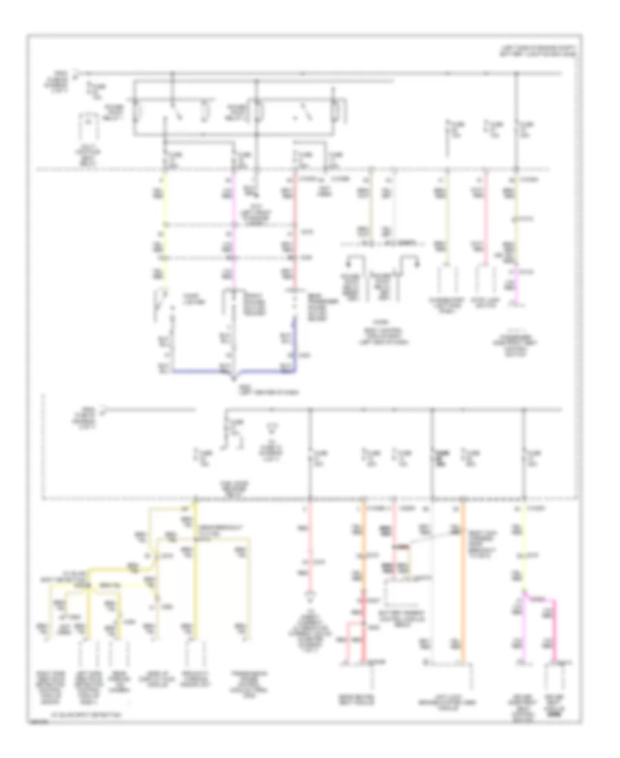
Power Distribution Wiring Diagram, Hybrid (3 of 7) for Ford Fusion S 2013
 https://portal-diagnostov.com/license.html
Automotive Electricians Portal FZCO
Automotive Electricians Portal FZCO
https://portal-diagnostov.com/license.html
https://portal-diagnostov.com/license.html
Automotive Electricians Portal FZCO
Automotive Electricians Portal FZCO
List of elements for Power Distribution Wiring Diagram, Hybrid (3 of 7) for Ford Fusion S 2013:
- (body main harness, near breakout to c913)
- (left side of engine compt) battery junction box (bjb)
- (near breakout to c192) s114
- (not used)
- (w/ blind spot detection)
- (w/ blind spot detection) s308
- Anti-lock brakes system (abs) module
- Battery energy control module (becm)
- Body control module (bcm) (left end of dash)
- C1010
- C1035a
- C1035b
- C215
- C219
- C2280c
- C2280i
- C263
- C3047
- C3053
- C3133
- C3304b
- C340
- C341a
- C406
- C4237a
- C922
- Charge port light ring (phev)
- Cigar lighter
- Driver seat module (dsm) (dsm) (dsm) (dsm)
- Driver side front seat control switch
- From fuse 20 (diagram 2 of 7)
- From fuse 68 (diagram 2 of 7)
- Front power outlet socket
- Fuel door release relay
- Fuse 10a
- Fuse 15a
- Fuse 20a
- Fuse 30a
- Fuse 40a
- Fuse 60a
- Fuse fuse fuse fuse 30a 30a 30a 30a
- G101 (left front of engine compt)
- G200 (left center of dash)
- Head up display (hud) module
- Left side obstacle detection control module (sod-l)
- Micro
- Multi contour seat relay
- Passenger side front seat control switch
- Power point relay 1
- Power point relay 2
- Power point relay reset (fet)
- Power point relay set (fet)
- Proximity warning radar unit
- Rear heated seat module
- Rear parking aid camera
- Rear passenger power outlet socket
- Red
- Right side obstacle detection control module (sod-r)
- S302
- S999
- Stop lamp switch
- To direct current/ alternating current (dc/ac) inverter (diagram 7 of 7)
- To fuse 72 (diagram 4 of 7)
- Transmission range control module (trcm) (mkz)
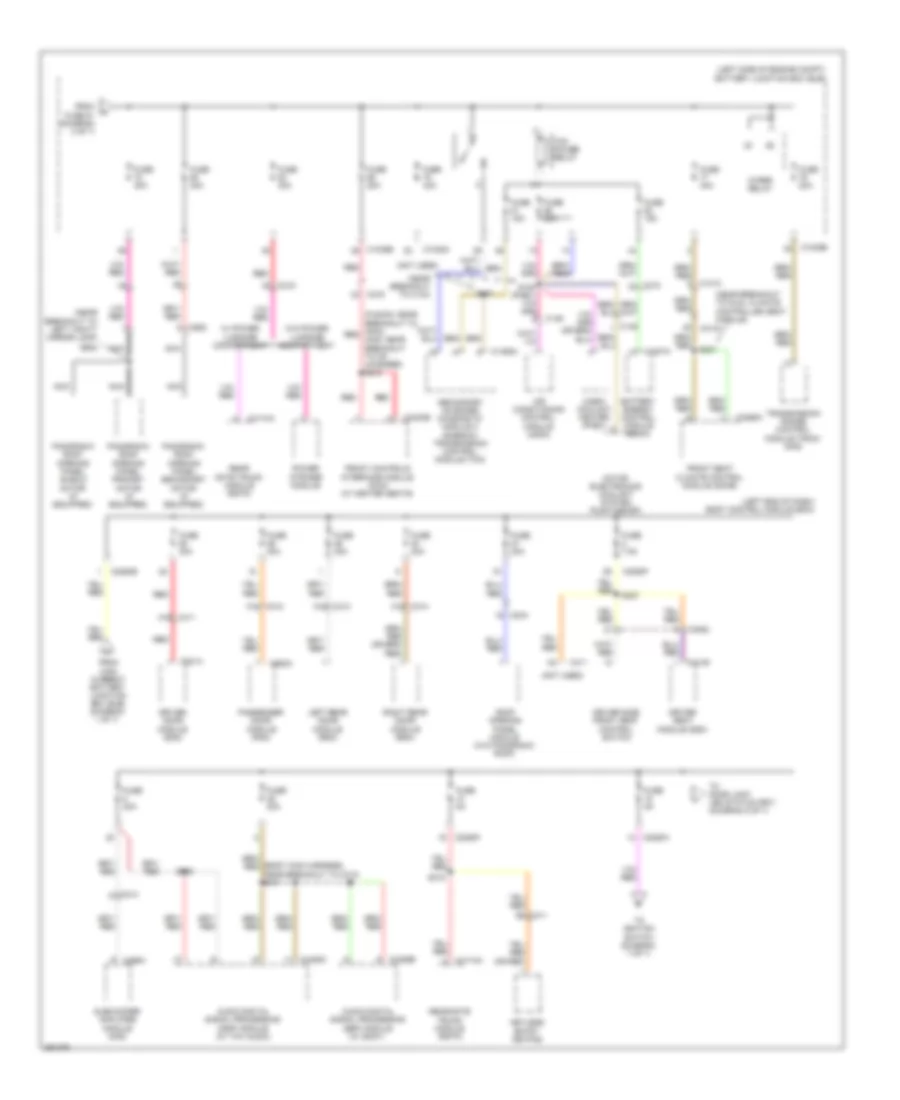
Power Distribution Wiring Diagram, Hybrid (4 of 7) for Ford Fusion S 2013
 https://portal-diagnostov.com/license.html
Automotive Electricians Portal FZCO
Automotive Electricians Portal FZCO
https://portal-diagnostov.com/license.html
https://portal-diagnostov.com/license.html
Automotive Electricians Portal FZCO
Automotive Electricians Portal FZCO
List of elements for Power Distribution Wiring Diagram, Hybrid (4 of 7) for Ford Fusion S 2013:
- (body main harness, near breakout to c313) s411
- (fusion: near breakout to apim) red (mkz: near breakout to cd changer) s210
- (left end of dash) body control module (bcm)
- (left side of engine compt) battery junction box (bjb)
- (near breakout to c134)
- (near breakout to dual climate controlled seat module)
- (near breakout to left vanity mirror lamp)
- (not used)
- A16
- Air conditioning control module (accm)
- Audio digital signal processing (dsp) module (w/ sony)
- Audio digital signal processing (dsp) module (w/ thx audio)
- B3 c311
- Battery energy control module (becm)
- C1010
- C1035a
- C1035b
- C145
- C1458a
- C146
- C214
- C215
- C219
- C2280b
- C2280f
- C2280h
- C2402b
- C3052
- C311
- C312
- C313
- C3133
- C314
- C3265a
- C341b
- C4174a
- C4237a
- C4326b
- C4452c
- C466a
- C501a
- C652a
- C919
- C925
- Cabin coolant heater (phev)
- Driver door module (ddm)
- Driver seat module (dsm)
- Driver side front seat control switch
- From fuse 81 (diagram 3 of 7)
- From high current battery junction box (bjb) (diagram 1 of 7)
- Front controls interface module (fcim) (w/ heated seats)
- Front seat climate control module (scme)
- Fuse 15a
- Fuse 20a
- Fuse 30a
- Fuse 40a
- Fuse 5a
- Fuse 7.5a
- Keyless entry keypad
- Left rear door module (rdm)
- Motor electronics coolant system pump (mecsp)
- Nca
- Panoramic roof opening panel primary motor (if equipped)
- Panoramic roof opening panel secondary motor (if equipped)
- Panoramic roof opening panel shield motor (if equipped)
- Passenger door module (pdm)
- Power striker module
- Rear gate trunk module (rgtm)
- Red
- Right rear door module (rdm)
- Roof opening panel module (w/o panoramic roof)
- S107
- S227
- S306
- S318
- S327
- S902
- Secondary on board diagnostic module c (sobdmc)/ transmission control module (tcm)
- Subwoofer amplifier module (mkz)
- Tcm power relay
- To door lock led status (fet) (diagram 5 of 7)
- To ignition switch (diagram 7 of 7)
- Transmission range control module (trcm) (mkz)
- W/ power luggage compartment
- W/o power luggage compartment
- Wiper relay
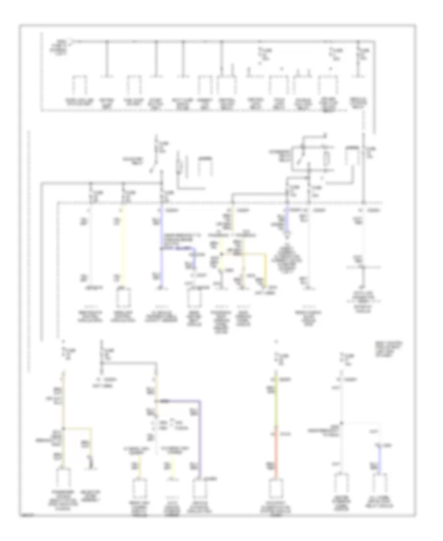
Power Distribution Wiring Diagram, Hybrid (5 of 7) for Ford Fusion S 2013
 https://portal-diagnostov.com/license.html
Automotive Electricians Portal FZCO
Automotive Electricians Portal FZCO
https://portal-diagnostov.com/license.html
https://portal-diagnostov.com/license.html
Automotive Electricians Portal FZCO
Automotive Electricians Portal FZCO
List of elements for Power Distribution Wiring Diagram, Hybrid (5 of 7) for Ford Fusion S 2013:
- (near breakout to parking brake switch) s219
- (not used)
- Accessory delay relay
- All wheel drive (awd) relay module
- Ambient ltg (fet)
- Auto dimming interior mirror
- Batt curr sns 5v fd (hb)
- Body control module (bcm) (left end of dash)
- C2280f
- C2280h
- C248
- C263
- C3047
- C310a
- C3133
- C3304b
- C4396c
- C900
- C919
- C925
- Central lock relay
- Central unlock relay
- Child lock relay
- Data link c0nnector (dlc)
- Decklid/ liftgate relay
- Door lock led status (fet)
- Double/ aux lock relay
- Driver/ fuel flap unlock relay
- From j fuse 18 (diagram 4 of 7)
- Fuel pump on (fet)
- Fuse 10a
- Fuse 15a
- Fuse 20a
- Fuse 30a
- Fuse 5a
- Fusion
- Gateway module
- Headlamp control module (hcm)
- Heated steering wheel module
- In vehicle temperature & humidity sensor
- Keypad illum (fet)
- Micro
- Mkz
- Nca
- Occupant classification system module (ocsm)
- Panoramic roof opening panel primary motor
- Passenger air bag deactivation (pad) indicator (fusion)
- Rear heated seat module
- Rear view camera display module
- Rear window blind module (mkz)
- Restraints control module (rcm)
- Roof opening panel module
- Run/start relay
- S212 (near breakout to g202)
- S220 (near breakout to pscm)
- S233
- S323
- Selector lever assembly
- Start button (fet)
- To direct current/ alternating current (dc/ac) inverter (diagram 7 of 7)
- Vehicle dynamics module (vdm)
- W/ panoramic
- W/ rear view camera
- W/o panoramic
- W/o rear view camera
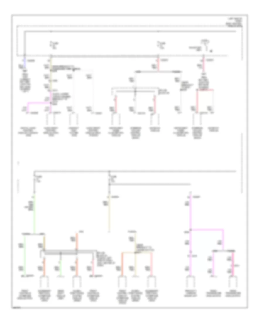
Power Distribution Wiring Diagram, Hybrid (6 of 7) for Ford Fusion S 2013
 https://portal-diagnostov.com/license.html
Automotive Electricians Portal FZCO
Automotive Electricians Portal FZCO
https://portal-diagnostov.com/license.html
https://portal-diagnostov.com/license.html
Automotive Electricians Portal FZCO
Automotive Electricians Portal FZCO
List of elements for Power Distribution Wiring Diagram, Hybrid (6 of 7) for Ford Fusion S 2013:
- (audio jumper wiring harness breakout to c214) s200
- (left end of dash) body control module (bcm)
- (near breakout to bcm) s206
- (near breakout to hazard switch) s211
- (near breakout to passenger knee airbag) s209
- Accessory protocol interface module (apim)
- Audio front control module (acim) (fusion)
- Audio front control module (acim) (mkz)
- C214
- C215
- C2280b
- C2280c
- C2280f
- C2280h
- C2402a
- C240a
- C2414a
- C263
- C4820b
- C4821a
- C913
- Compact disc player (mkz)
- Digital audio control module c (dacmc) (mkz)
- From battery junction box (bjb) (diagram 2 of 7)
- From high current battery junction box (bjb) (diagram 1 of 7)
- Front control/ display interface module (fcdim)
- Front controls interface module (fcim)
- Fuse 10a
- Fuse 20a
- Fuse 7.5a
- Fusion
- Gateway module
- Gear shift module (gsm)
- Global positioning system module (gpsm)
- Instrument panel cluster (ipc) module
- Micro
- Mkz
- Proximity warning radar unit
- Radio transceiver module (rtm)
- Run/start (fet)
- S305
- Splice block 22 (fusion: left side of dash) (mkz: center of dash)
- Splice block 26
- Steering column control module (sccm)
Power Distribution Wiring Diagram, Hybrid (7 of 7) for Ford Fusion S 2013
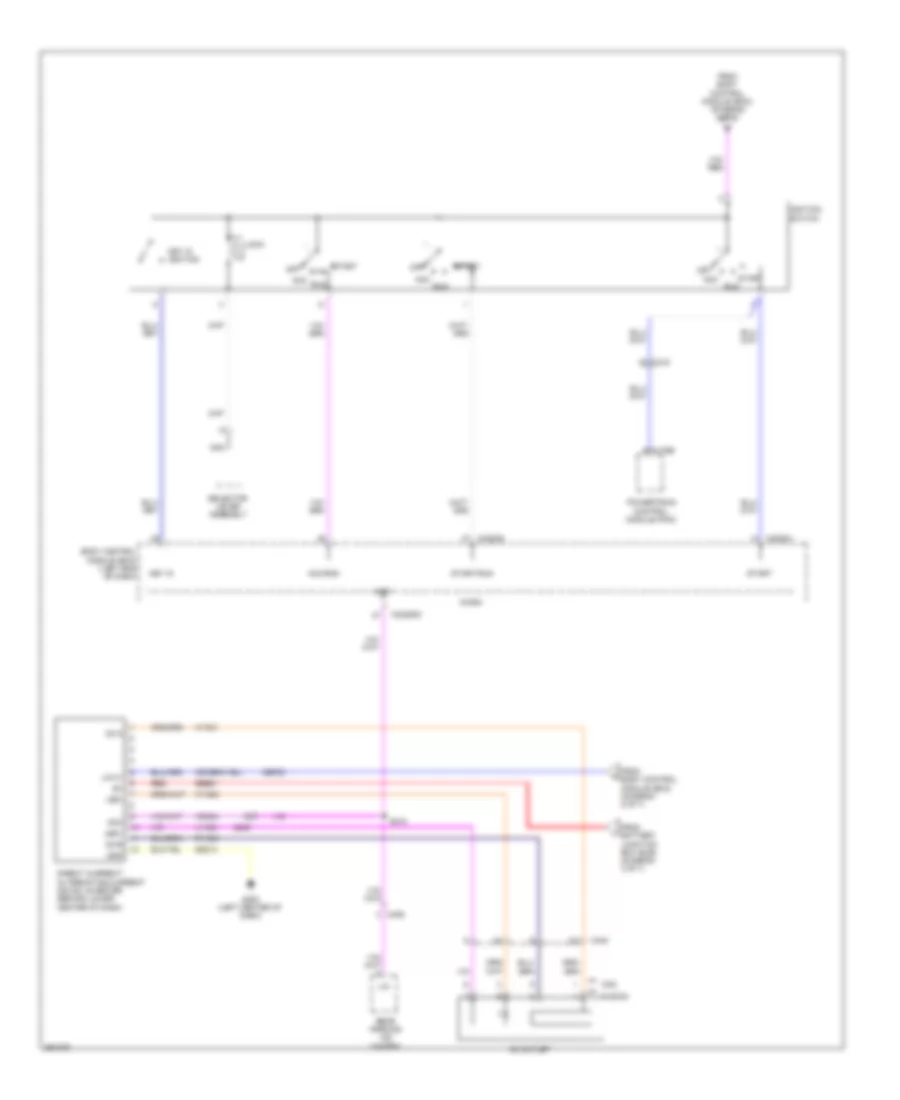 https://portal-diagnostov.com/license.html
Automotive Electricians Portal FZCO
Automotive Electricians Portal FZCO
https://portal-diagnostov.com/license.html
https://portal-diagnostov.com/license.html
Automotive Electricians Portal FZCO
Automotive Electricians Portal FZCO
List of elements for Power Distribution Wiring Diagram, Hybrid (7 of 7) for Ford Fusion S 2013:
- Ac outlet
- Ac-a
- Ac-b
- Acc
- Acc/run
- Body control module (bcm) (left end of dash)
- C175b
- C219
- C2280g
- C2280h
- C248
- C32280d
- C340
- C406
- Cbp23
- Direct current/ alternating current (dc/ac) inverter (behind lower center of dash)
- From battery junction box (bjb) (diagram 3 of 7)
- From body control module (bcm) (diagram 4 of 7)
- From body control module (bcm) (diagram 5 of 7)
- Fusion
- G200 (left center of dash)
- Gd214
- Gnd
- Hya01
- Hya02
- Ignition switch
- Key in
- Key in ignition
- Led+
- Led-
- Lin
- Lin 01
- Lock
- Lya03
- Micro
- Mkz
- Nca
- Off
- Powertrain control module (pcm)
- Rear parking aid camera
- Red
- Run
- Rya03
- S310
- Sbb81
- Selector lever assembly
- Start
- Start/run
- Vdn04

 Deutsch
 English
 English
 Español
 Français
 Nederlands
 Русский


