POWER DISTRIBUTION
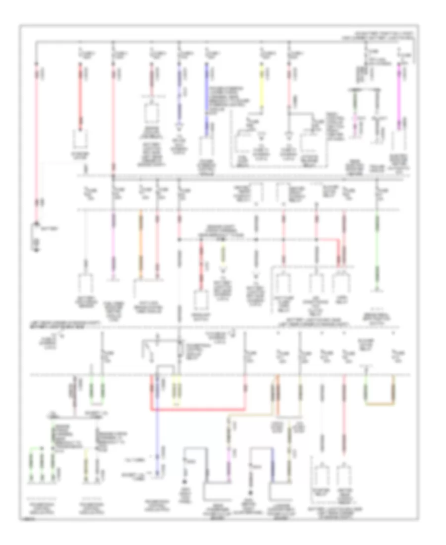
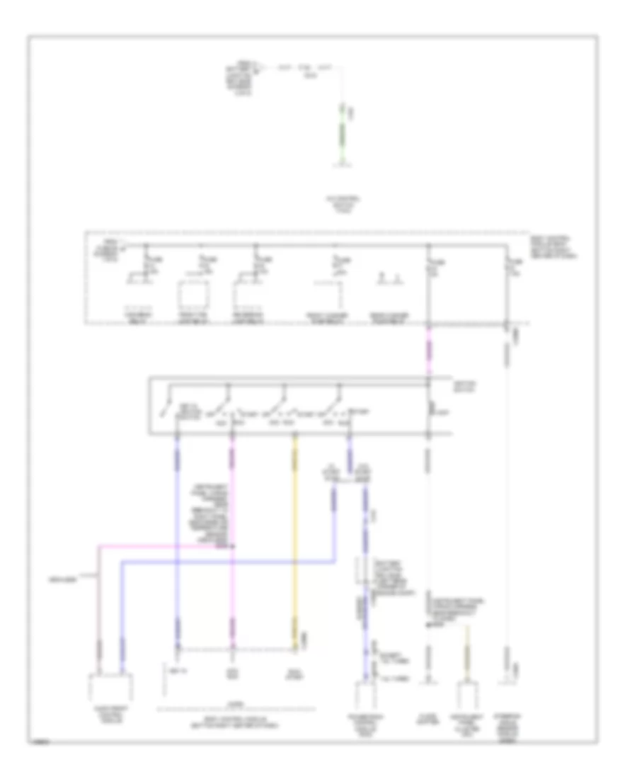
Power Distribution Wiring Diagram (1 of 8) for Ford Transit Connect Titanium 2014
 https://portal-diagnostov.com/license.html
Automotive Electricians Portal FZCO
Automotive Electricians Portal FZCO
https://portal-diagnostov.com/license.html
https://portal-diagnostov.com/license.html
Automotive Electricians Portal FZCO
Automotive Electricians Portal FZCO
List of elements for Power Distribution Wiring Diagram (1 of 8) for Ford Transit Connect Titanium 2014:
- (diagram 4 of 8)
- (diagram 5 of 8)
- (engine compt wiring harness, near breakout to bjb) s131
- (left rear corner of engine compt) battery junction box (bjb)
- (on battery positive (+) post) high current battery junction box
- (power steering jumper wiring harness, near breakout to power steering control module) s151
- (van) (wagon)
- 1.6l turbo
- Air conditioning (a/c) clutch relay
- Anti-lock brake system (abs) module
- Anti-thief alarm horn relay
- Battery
- Battery junction box (bjb) (left rear corner of engine compt)
- Battery monitoring sensor
- Blower motor relay
- Body control module (bottom right center of dash)
- Brake pedal (bpp) position switch
- C1035c
- C1463a
- C1617a
- C1617b
- C1617c
- C1617d
- C1617e
- C1617f
- C1617g
- C1617h
- C1617j
- C1617l
- C175b
- C1915b
- C211
- C212
- C213
- C2280g
- C2603a
- C315
- C3443a
- C4379a
- Electric booster heater (automatic a/c)
- Engine cooling fan relay
- Except 1.6l turbo
- Fuel fired booster heated module (van)
- Fuel pump relay
- Fuse 1 80a
- Fuse 10a
- Fuse 15a
- Fuse 2 150a
- Fuse 20a
- Fuse 25a
- Fuse 3 100a
- Fuse 30a
- Fuse 4 50a
- Fuse 40a
- Fuse 40a 80a
- Fuse 5a
- Fuse 6 70a
- Fuse 8 50a
- Fuse 80a
- Fuse 9 50a
- G203 (right kick panel)
- G402 (behind right quarterpanel)
- Headlamp switch
- Heated front window relay
- Heated rear window relay
- Horn relay
- Liftgate release relay
- Luggage compartment power outlet socket
- Power steering control module
- Powertrain control module (pcm)
- Powertrain control module relay
- Rear electric booster heater
- Rear passenger power outlet socket
- Red
- S318
- S322
- Starter motor
- Starter relay
- To battery junction box (bjb) (diagram 2 of 8)
- To battery junction box (bjb) (diagram 8 of 8)
- To fuse 26 (diagram 3 of 8)
- To fuse 33 (diagram 2 of 8)
- To fuse 70
- To fuse 74
- To splice s410 (diagram 6 of 8)
- Trailer module
- Transmission) s115
- Van
- Van w/ start stop
- W/0 start stop
- Wagon
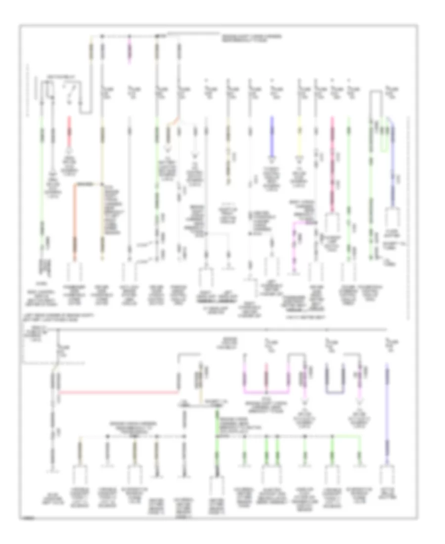
Power Distribution Wiring Diagram (2 of 8) for Ford Transit Connect Titanium 2014
 https://portal-diagnostov.com/license.html
Automotive Electricians Portal FZCO
Automotive Electricians Portal FZCO
https://portal-diagnostov.com/license.html
https://portal-diagnostov.com/license.html
Automotive Electricians Portal FZCO
Automotive Electricians Portal FZCOList of elements for Power Distribution Wiring Diagram (2 of 8) for Ford Transit Connect Titanium 2014:
- (body wiring harness, near breakout to g200) s343
- (engine compt wiring harness, near breakout to bjb)
- (engine compt wiring harness, near breakout to bjb) s132
- (engine wiring harness, near breakout to ignition coil-on-plug 4) s119
- (engine wiring harness, near breakout to transmission) s115
- (heated windshield washer wiring harness) s144
- (left rear corner of engine compt) battery junction box (bjb)
- 1.6l turbo
- 2 way
- 4 way
- A13
- Active grille shutter
- Adaptive front lighting module
- Anti-lock brake system (abs) module
- Body control module (bottom right center of dash)
- C1035c
- C1463b
- C175b
- C1915b
- C211
- C212
- C214
- C2280d
- C3049
- C3050
- C315
- C319
- C327
- C504c
- C510
- C566b
- C9071a
- Control relay ignition
- Driver door window control switch
- Driver side front heated seat module
- Driver side windshield wiper motor
- Electric exhaust gas recirculation (eegr) assembly
- Engine cooling fan relay
- Evap canister vent valve
- Evaporative emission purge valve
- Except 1.6l turbo
- Floor shifter
- From fuse 32 g (diagram 1 of 8)
- From splice s131 (diagram 1 of 8)
- From splice s133 (diagram 3 of 8)
- Fuse 10a
- Fuse 15a
- Fuse 20a
- Fuse 25a
- Fuse 40a
- Fuse 5a
- Heated oxygen sensor (ho2s) 12
- Ignition relay
- Left headlamp assembly
- Left windshield heated washer jet
- Mass air flow intake air temperature (maf/iat) sensor
- Micro
- Nca
- Parking assist control module (pam)
- Passenger side front heated seat module
- Passenger side windshield wiper motor
- Power steering control module (pscm)
- Powertrain control module (pcm)
- Red
- Right headlamp assembly
- Right windshield heated washer jet
- S129
- S132 (engine compt wiring harness, near breakout to bjb)
- S140 (engine compt wiring harness, near breakout to left front wheel speed sensor)
- Taxiroof lamp switch (taxi)
- To a/c control switch (diagram 5 of 8)
- To battery junction box (bjb) (diagram 4 of 8)
- To body control module (bcm) (diagram 4 of 8)
- To splice s114 & s118 (diagram 3 of 8)
- To splice s117 & s113 (diagram 3 of 8)
- To splice s135 (diagram 3 of 8)
- Universal heated oxygen sensor (ho2s)
- Universal heated oxygen sensor (ho2s) 11
- Van w/ heated seat
- Variable camshaft timing 11 (vct 11) solenoid
- Variable camshaft timing 12 (vct 12) solenoid
- W/ headlamp leveling
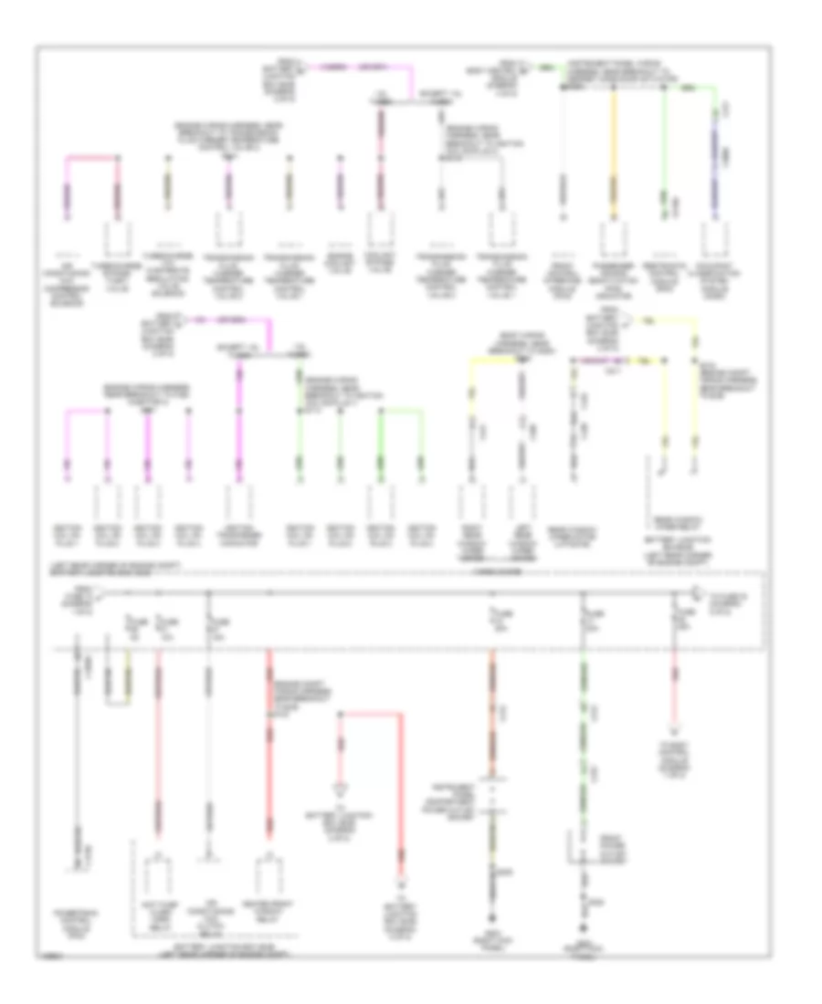
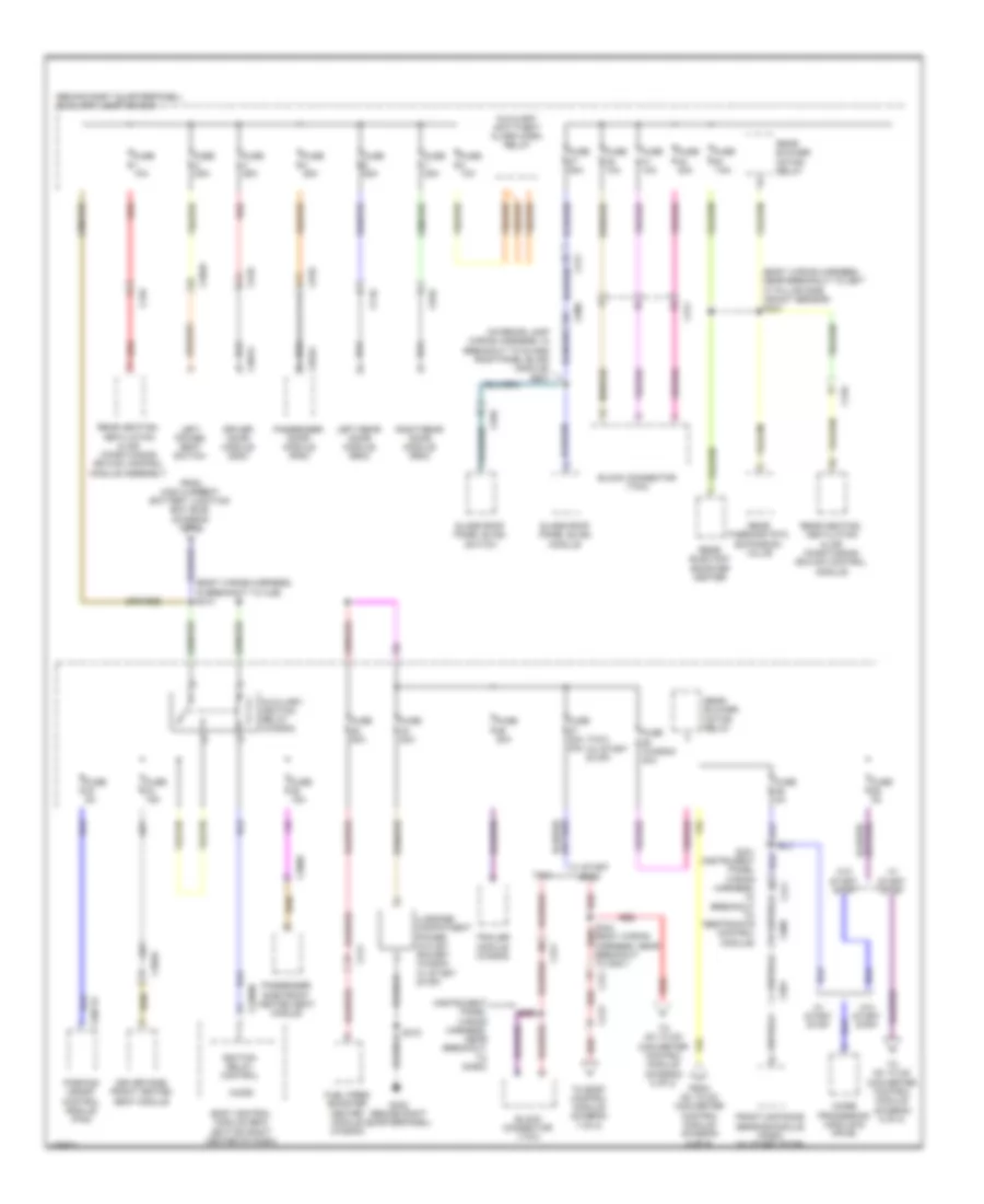
Power Distribution Wiring Diagram (3 of 8) for Ford Transit Connect Titanium 2014
 https://portal-diagnostov.com/license.html
Automotive Electricians Portal FZCO
Automotive Electricians Portal FZCO
https://portal-diagnostov.com/license.html
https://portal-diagnostov.com/license.html
Automotive Electricians Portal FZCO
Automotive Electricians Portal FZCOList of elements for Power Distribution Wiring Diagram (3 of 8) for Ford Transit Connect Titanium 2014:
- (body wiring harness, near breakout to g200) s206
- (engine compt wiring harness, near breakout to bjb) s133
- (engine wiring harness, near breakout to fuel injector 3) s117
- (engine wiring harness, near breakout to ignition coil-on-plug 1) s113
- (engine wiring harness, near breakout to ignition coil-on-plug 4) s118
- (engine wiring harness, near breakout to transmission fluid warmer temperature control valve 2) s114
- (instrument panel wiring harness, near breakout to defrost mode door actuator) s239
- (left rear corner of engine compt) battery junction box (bjb)
- 1.6l turbo
- Air conditioning (a/c) clutch relay
- Air conditioning (a/c) compressor control solenoid
- Anti-thief alarm horn relay
- Battery junction box (bjb) (left rear corner of engine compt)
- Battery junction box(bjb) (left rear corner of engine compt)
- C1035c
- C175b
- C211
- C212
- C3050
- C310a
- C311
- C315
- C405
- C421
- C432
- C438
- Cargo doors
- Coolant bypass valve
- Engine coolant valve
- Except 1.6l turbo
- From battery junction box (bjb) (diagram 2 of 8)
- From battery k junction box (bjb) (diagram 2 of 8)
- From battery l junction box (bjb) (diagram 2 of 8)
- From body control r module (diagram 4 of 8)
- From fuse 12 f (diagram 1 of 8)
- Front control interface module (fcim)
- Front power outlet socket
- Fuse 10a
- Fuse 15a
- Fuse 20a
- Fuse 25a
- Fuse 5a
- G203 (right kick panel)
- Heated front window relay
- Ignition coil on plug 1
- Ignition coil on plug 2
- Ignition coil on plug 3
- Ignition coil on plug 4
- Ignition tranformer capacitor
- Instrument panel compartment power outlet socket
- Left rear window wiper motor
- Occupant classfication system module (ocsm)
- Passenger air bag deactivation (pad) indicator
- Powertrain control module (pcm)
- Rear window wiper motor (liftgate)
- Rear window wiper relay
- Red
- Restraints control module (rcm)
- Right rear window wiper motor
- S135 (engine compt wiring harness, near breakout to bjb)
- S238
- S322
- To battery junction box (bjb) (diagram 2 of 8)
- To battery junction box (bjb) (diagram 8 of 8)
- To body control module (diagram 7 of 8)
- To fuse 30 (diagram 8 of 8)
- Transimission fluid warmer temperature control valve 1
- Transimission fluid warmer temperature control valve 2
- Turbocharge (tc) wastegate regulating valve solenoid
- Turbocharge bypass (tcby) valve
Power Distribution Wiring Diagram (4 of 8) for Ford Transit Connect Titanium 2014
 https://portal-diagnostov.com/license.html
Automotive Electricians Portal FZCO
Automotive Electricians Portal FZCO
https://portal-diagnostov.com/license.html
https://portal-diagnostov.com/license.html
Automotive Electricians Portal FZCO
Automotive Electricians Portal FZCOList of elements for Power Distribution Wiring Diagram (4 of 8) for Ford Transit Connect Titanium 2014:
- (body wiring harness, near breakout to restraints control module) s325
- (bottom right center of dash) body control module
- (instrument panel wiring harness, near breakout to defrost mode door actuator) s241
- (interior lamp wiring harness, in breakout to glass roof panel blind module) (w/ roof opening panel) s909
- (w/o crew chief) (w/ crew chief)
- (wiring harness - center console, near breakout to c315) s323
- Auto-dimming interior mirror (w/o rearview camera) rearview camera display mirror (w/ rearview camera)
- Autolamp & rain sensor
- Auxiliary data link connector (dlc)
- Battery junction box (bjb) (left rear corner of engine compt)
- Battery saver saver relay (taxi)
- C212
- C215
- C2280d
- C2280e
- C2280f
- C2280h
- C2357a
- C2603c
- C311
- C315
- C510
- C9056a
- C931a
- C934
- C935
- C991
- Center lock relay (w/o door modules)
- Center unlock relay (w/o door modules)
- City safe
- Data link connector (dlc)
- Driver heated seat switch
- Electric booster heater
- From battery junction box (bjb) (diagram 2 of 8)
- From fuse 65 c (diagram 1 of 8)
- Front interior lamp
- Fuse 10a
- Fuse 20a
- Fuse 5a
- Fuse 7.5a
- Fuse 7.5a 10a
- Glass roof panel blind module (w/ roof opening panel)
- Glove compartment lamp
- Heating, ventilation & air conditioning (hvac) module
- In-vehicle temperature/ humidity sensor
- Inline fuse (left side of dash)
- Interior light relay
- Intrusion sensor
- Left luggage compartment lamp
- Luggage compartment lamp
- Master window control switch
- Micro
- Passenger heated seat switch
- Passive anti-theft system (pats) transceiver
- Right luggage compartment lamp
- S229 (instrument panel wiring harness, near breakout to sasm)
- S260 (crew chief wiring harness, near breakout to telematics module)
- S261 (crew chief wiring harness, near breakout to telematics module)
- Telematics module
- Telematics module (crew chief)
- To dc to dc converter control module (diagram 8 of 8)
- To splice s239 (diagram 3 of 8)
- To splice s910 (diagram 7 of 8)
- W/ crew chief
- W/o crew chief
Power Distribution Wiring Diagram (5 of 8) for Ford Transit Connect Titanium 2014
 https://portal-diagnostov.com/license.html
Automotive Electricians Portal FZCO
Automotive Electricians Portal FZCO
https://portal-diagnostov.com/license.html
https://portal-diagnostov.com/license.html
Automotive Electricians Portal FZCO
Automotive Electricians Portal FZCOList of elements for Power Distribution Wiring Diagram (5 of 8) for Ford Transit Connect Titanium 2014:
- (instrument panel wiring harness, near breakout to right panel discharge air temperature sensor) (mechless) s235
- (instrument panel wiring harness, near breakout to sasm) s225
- 1.6l turbo
- A/c control switch (taxi)
- Acc
- Acc run
- Acc/ run
- Audio front control module
- Battery junction box (bjb) (left rear corner of c1035c engine compt)
- Body control module (bcm) (bottom right center of dash)
- Body control module (bottom right center of dash)
- C175b
- C1915b
- C212
- C226a
- C2280c
- C2280f
- C315
- Except 1.6l turbo
- Floor shifter
- From battery z junction box (bjb) (diagram 2 of 8)
- From fuse 56 b (diagram 1 of 8)
- Front fog lamp relay
- Front washer pump relay
- Fuse 10a
- Fuse 15a
- Fuse 20a
- Fuse 5a
- Fuse 7.5a
- High beam relay
- Ignition switch
- Instrument panel cluster (ipc)
- Key in
- Key in ignition switch
- Lock
- Mechless
- Micro
- Off
- Powertrain control module (pcm)
- Rear washer pump relay
- Reversing lamp relay
- Run
- Run/ start
- Start
- Steering angle sensor module (sasm)
- W/ start stop
- W/o start stop
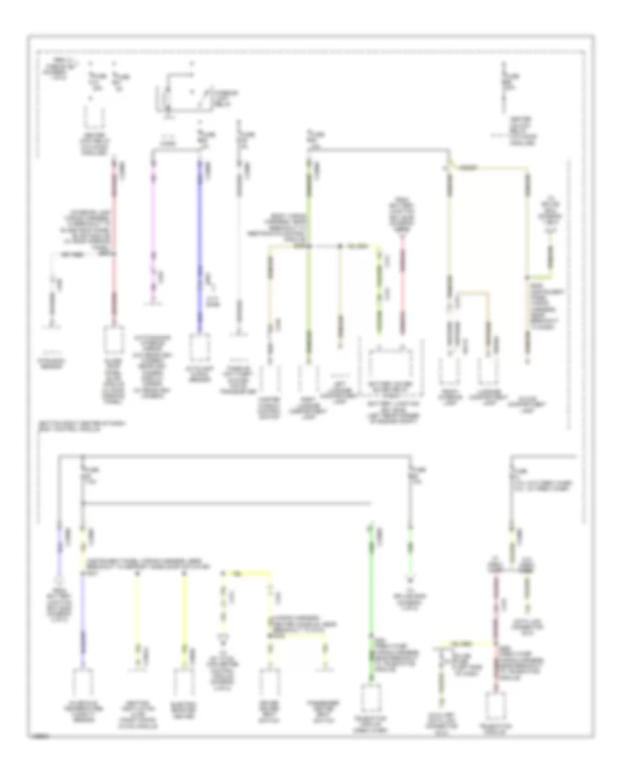
Power Distribution Wiring Diagram (6 of 8) for Ford Transit Connect Titanium 2014
 https://portal-diagnostov.com/license.html
Automotive Electricians Portal FZCO
Automotive Electricians Portal FZCO
https://portal-diagnostov.com/license.html
https://portal-diagnostov.com/license.html
Automotive Electricians Portal FZCO
Automotive Electricians Portal FZCOList of elements for Power Distribution Wiring Diagram (6 of 8) for Ford Transit Connect Titanium 2014:
- (behind right quarterpanel) auxiliary junction box
- (body wiring harness, in breakout to ajb) s410
- (body wiring harness, near breakout to left "c" pillar side impact sensor) s324
- (instrument panel wiring harness, near breakout to sasm)
- (interior lamp wiring harness, in breakout to glass roof panel blind module) s907
- (taxi)
- (w/ start stop)
- A14
- Auxiliary anti-theft alarm horn relay
- Auxiliary ignition relay (wagon)
- Block connector (taxi)
- Body control module (bcm) (bottom right center of dash)
- C211
- C212
- C2280b
- C3049
- C3050
- C311
- C316
- C501a
- C510
- C610
- C652a
- C710
- C810
- C900
- C9071a
- C935
- C991
- Driver door module (ddm)
- Driver side front heated seat module
- From dc to dc converter control module (diagram 8 of 8)
- From high current battery junction box (bjb) (diagram 1 of 8)
- Front distance sensing module (fdsm) (w/ start stop)
- Fuel fired booster heater module (wagon)
- Fuse (wagon) 40a
- Fuse 10a
- Fuse 15a
- Fuse 20a
- Fuse 25a
- Fuse 40a 30a
- Fuse 5a
- Fuse 7.5a
- G402 (behind right quarterpanel)
- Glass roof panel blind module
- Glass roof panel blind switch
- Ignition relay control
- Image processing module b (ipm-b)
- Left power seat switch
- Left rear door module (rdm)
- Luggage compatment power outlet socket (wagon w/ start stop)
- Micro
- Parking assist control module (pam)
- Passenger door module (pdm)
- Passenger side front heated seat module
- Rear blower motor relay
- Rear electric booster heater
- Rear heating, ventilation & air conditioning (rhvac) control module
- Rear heating, ventilation & air conditioning (rhvac) control module assembly
- Rear thermostatic expansion valve
- Red
- Right rear door module (rdm)
- S259
- S318
- S331 (instrument panel wiring harness, in breakout to restraints control module)
- S344 red (body wiring harness, near breakout to g301)
- Taxi
- To body control module (diagram 7 of 8)
- To dc to dc converter control module (diagram 8 of 8)
- Trailer module (wagon)
- W/ start stop
- W/0 start stop
- W/o start stop
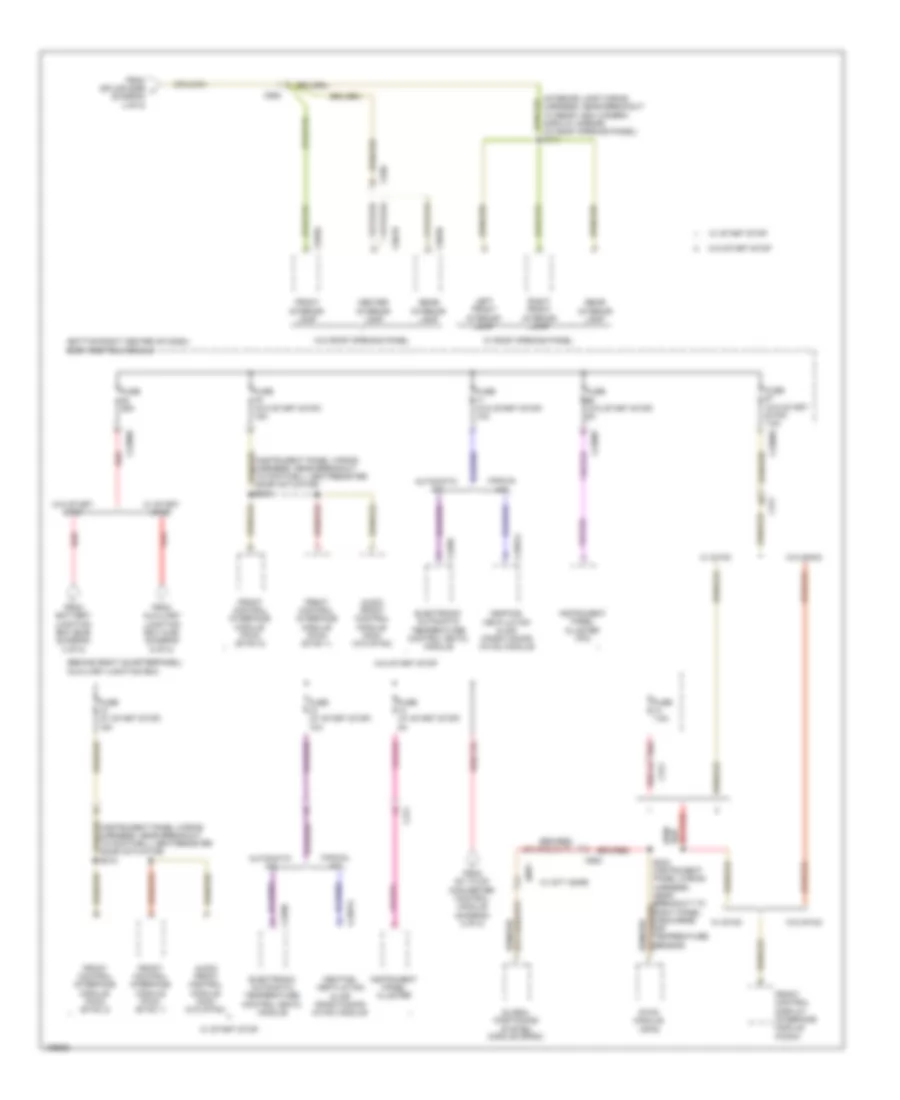
Power Distribution Wiring Diagram (7 of 8) for Ford Transit Connect Titanium 2014
 https://portal-diagnostov.com/license.html
Automotive Electricians Portal FZCO
Automotive Electricians Portal FZCO
https://portal-diagnostov.com/license.html
https://portal-diagnostov.com/license.html
Automotive Electricians Portal FZCO
Automotive Electricians Portal FZCOList of elements for Power Distribution Wiring Diagram (7 of 8) for Ford Transit Connect Titanium 2014:
- (behind right quarterpanel)
- (bottom right center of dash)
- (instrument panel wiring harness, near breakout to footwell vent/register door actuator) s215
- (interior lamp wiring harness, near breakout to rear view camera display mirror) (w/ roof opening panel) s910
- Audio front control module (acm) (w/o sync)
- Automatic a/c
- Auxiliary junction box
- Body control module
- C2280d
- C2280e
- C2280f
- C228b
- C2357a
- C311
- C900
- C929a
- C936
- C961b
- C963b
- C991
- Center interior lamp
- Electronic automatic temperature control (eatc) module
- From auxiliary junction box (ajb) (diagram 6 of 8)
- From battery junction box (bjb) (diagram 3 of 8)
- From dc to dc converter control module (diagram 8 of 8)
- From splice s299 j (diagram 4 of 8)
- Front control display interface module (fcdim)
- Front control interface module (fcim) (sync 1)
- Front control interface module (fcim) (sync 2)
- Front interior lamp
- Fuse (w/ start stop) 10a
- Fuse (w/ start stop) 15a
- Fuse (w/ start stop) 5a
- Fuse (w/o start stop) 10a
- Fuse (w/o start stop) 15a
- Fuse (w/o start stop) 5a
- Fuse (w/o start stop) 7.5a
- Fuse 25a
- Fuse 7.5a
- Global postioning system module (gpsm)
- Heating, ventilation & air conditioning (hvac) module
- Instrument panel cluster
- Instrument panel cluster (ipc)
- Left front interior lamp
- Manual a/c
- Rear interior lamp
- Red
- Right front interior lamp
- S234 (instrument panel wiring harness, near breakout to right panel discharge air temperature sensor)
- Sync module (apim)
- W/ city safe
- W/ roof opening panel
- W/ start stop
- W/ sync
- W/o roof opening panel
- W/o start stop
- W/o sync
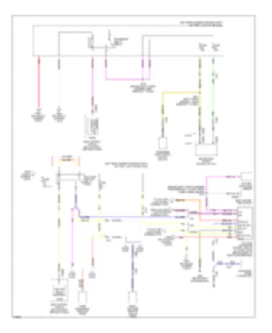
Power Distribution Wiring Diagram (8 of 8) for Ford Transit Connect Titanium 2014
 https://portal-diagnostov.com/license.html
Automotive Electricians Portal FZCO
Automotive Electricians Portal FZCO
https://portal-diagnostov.com/license.html
https://portal-diagnostov.com/license.html
Automotive Electricians Portal FZCO
Automotive Electricians Portal FZCOList of elements for Power Distribution Wiring Diagram (8 of 8) for Ford Transit Connect Titanium 2014:
- (diagram 6 of 8)
- (engine compt wiring harness, near breakout to left front wheel speed sensor) s141
- (left rear corner of engine compt) battery junction box (bjb)
- (not used)
- 2 way
- 4 way
- A11
- A14
- Accessory
- Accessory delay relay
- Auxiliary ignition relay (van)
- Battery monitoring sensor
- Body control module (bcm)
- Body control module (bottom right center of dash)
- C192
- C211
- C2280a
- C2280b
- C311
- C504a
- C504b
- C510
- C566a
- C610
- C900
- C991
- Control delay relay
- Dc to dc converter control module (w/ start stop) (behind front of right quarterpanel)
- Driver door window control switch
- From auxiliary x junction box (diagram 6 of 8)
- From fuse 48 m (diagram 3 of 8)
- From splice s131 (diagram 1 of 8)
- From splice s133 (diagram 3 of 8)
- From splice s241 (diagram 4 of 8)
- From u splice s344 (diagram 6 of 8)
- Front distance sensing module (fdsm)
- Fuse 25a
- Fuse 5a
- G303 (behind right quarterpanel)
- Gnd
- Ign
- Ign out
- Ign sw sig
- Ignition relay control
- Image processing module b (ipm-b)
- Instrument panel cluster (ipc)
- Lin
- Micro
- Passenger door window control switch
- Pwr
- Pwr out
- Red
- S128 (engine compt wiring harness, near breakout to bjb)
- S201 (body wiring assembly, near breakout to g200)
- To auxiliary junction box (diagram 7 of 8)
- To auxiliary junction box v
- Van
- W/ start stop
- W/0 start stop
- Wagon

 Čeština
 Dansk
Dansk Deutsch
 Ελληνικά
 English
 English
 Español
 Suomi
Suomi Français
 Français
 עברית
עברית Hrvatski
 Magyar
 Italiano
 한국어
한국어 Nederlands
 Polski
 Português
 Português
 Română
 Русский
 Slovenčina
 Slovenščina
 Svenska
 Türkçe
 中文 (中国)
