POWER DISTRIBUTION
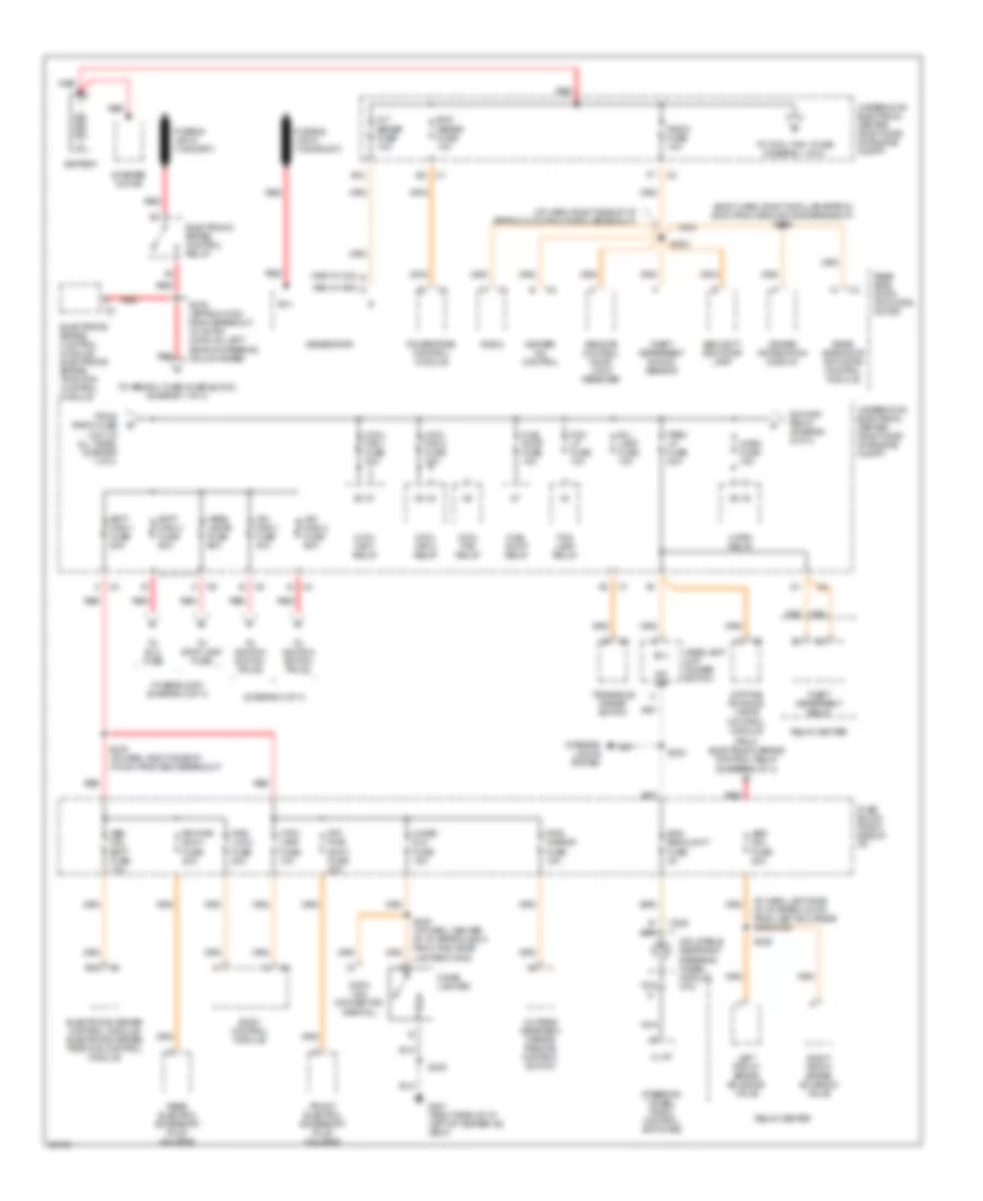
Power Distribution Wiring Diagram (1 of 4) for Oldsmobile Silhouette GL 1997
 https://portal-diagnostov.com/license.html
Automotive Electricians Portal FZCO
Automotive Electricians Portal FZCO
https://portal-diagnostov.com/license.html
https://portal-diagnostov.com/license.html
Automotive Electricians Portal FZCO
Automotive Electricians Portal FZCO
List of elements for Power Distribution Wiring Diagram (1 of 4) for Oldsmobile Silhouette GL 1997:
- (body harn, right b-pillar approx 20cm from ground g305 breakout) s326
- (diagram 3 of 4)
- (fuse block) (diagram 2 of 4)
- (i/p harn, right side of i/p approx 21cm from radio breakout)
- (k68 w/ c60) d
- (kg9 w/ c34) s
- Abs mdl batt fuse 10a
- Abs sol fuse 20a
- Alt sense fuse 10a
- B(+)
- B/u lamp fuse 10a
- B12
- Batt main 1 fuse 60a
- Batt main 2 fuse 60a
- Battery
- Body control module
- C205
- Cigar lighter
- Cigar/ dlc fuse 15a
- Cool fan 1 fuse 30a
- Cool fan 1 relay
- Cool fan 2 fuse 30a
- Cool fan 2 relay
- Cool fan relay
- Ctsy lamp fuse 10a
- Data link connector (partial)
- Daytime running lamps control module
- Driver information display
- E12
- Ecm sense fuse 10a
- Electronic brake control module/ electronic brake traction control module
- Electronic brake control relay
- Fog lamp relay
- Fog lp fuse 10a
- From electronic brake control relay (diagram 1 of 4)
- From radio fuse (hot at all times) (diagram 1 of 4)
- Front electric accessory plug housing
- Frt pwr sckt fuse 20a
- Fuel pump fuse 15a
- Fuel pump relay
- Fuse block (right side of i/p)
- Fusible link a (10ga-rust)
- G201 (right side of i/p, left of heater-a/c vent)
- Generator
- Head- lamps fuse 60a
- Headlamp & i/p dimmer switch
- Heater/ a/c control
- Horn fuse 15a
- Horn relay
- I/p harn, left side of i/p approx 21cm from left bulkhead grommet)
- Ign main 1 fuse 40a
- Ign main 2 fuse 60a
- Ign main relay (diagram 2 of 4)
- Illum
- Inc dim
- Inflatable restraint steering wheel module coil
- Interior lights system
- Left front brake solenoid valve
- Nca
- Outside rearview mirror remote control switch
- Park lp fuse 20a
- Powertrain control module
- Pwr lock fuse 20a
- Pwr mirror fuse 10a
- Radio
- Radio fuse 10a
- Rear electric accessory plug housing
- Rear side door actuator control module
- Rear side door actuator motor
- Red
- Relay center
- Remote control door lock receiver
- Right front brake solenoid valve
- Rr pwr sckt fuse 20a
- S202
- S203
- S230
- S235
- S238 (i/p harn, center of i/p approx 80cm from the cigar lighter conn)
- S276 (i/p harn, right side of i/p 8cm from bcm breakout)
- S279 (approx 12cm from breakout to 48-pin conn on left side of steering column base)
- Security indicator lamp
- Starter motor
- Steering wheel radio control switches
- Swc backlight fuse 2a
- Theft deterrent relay
- Theft deterrent shock sensor
- To abs sol fuse (fuse block) (diagram 1 of 4)
- To cool fan 1 fuse (diagram 1 of 4)
- To elc fuse
- To ignition switch pin d2
- To ignition switch pin d5
- To stop lamp fuse
- Transaxle range switch
- Underhood electrical center (right side of engine compt)
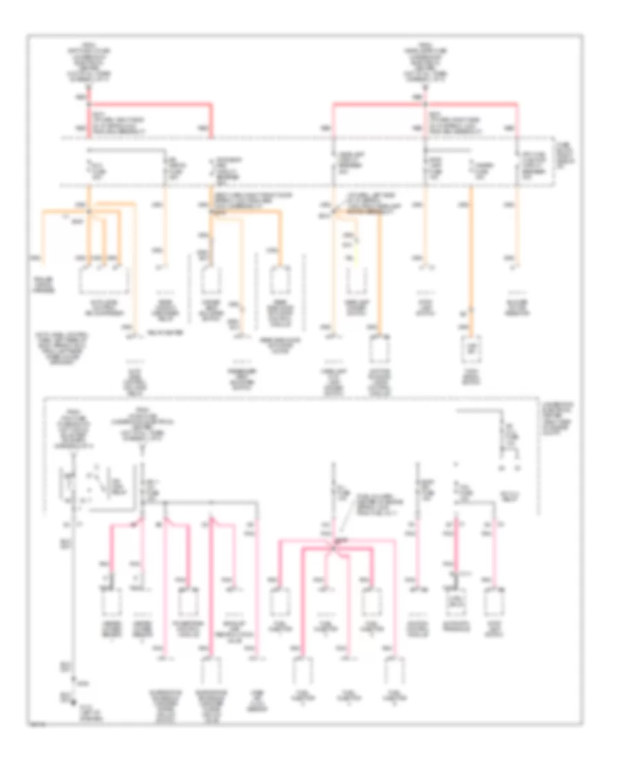
Power Distribution Wiring Diagram (2 of 4) for Oldsmobile Silhouette GL 1997
 https://portal-diagnostov.com/license.html
Automotive Electricians Portal FZCO
Automotive Electricians Portal FZCO
https://portal-diagnostov.com/license.html
https://portal-diagnostov.com/license.html
Automotive Electricians Portal FZCO
Automotive Electricians Portal FZCOList of elements for Power Distribution Wiring Diagram (2 of 4) for Oldsmobile Silhouette GL 1997:
- (auto level control harn, left rear of body approx 16cm from left rear wheelhouse grommet)
- (body harn, right front door approx 13cm from srs module breakout) s302
- (fuel inj harn, center of engine approx 12cm from fuel inj 1)
- (i/p harn, left side of i/p approx 13cm from headlamp switch breakout)
- (underhood electrical center) (hot at all times) (diagram 1 of 4)
- A/c clu fuse 10a
- A/c clu relay
- A12
- Auto level control air comprssor
- Auto level control inflator relay
- Automatic transaxle
- Blower motor resistor
- C111
- Ctrl sols
- Daytime running lamps control module
- Driver seat adjuster switch
- E10
- Elc fuse 20a
- Elek ign fuse 15a
- Evaporative emissions canister purge vacuum switch
- Evaporative emissions canister purge vacuum valve
- Exhaust gas recirculation valve
- From batt main 2 fuse
- From headlamps fuse
- From horn fuse (underhood electrical center) (hot at all times) (diagram 1 of 4)
- From pcm fuse (fuse block) (hot in run, bulb test or start) (diagram 3 of 4)
- Frt hvac hi blowr circuit breaker 30a
- Fuel injector
- Fuse block (right side of i/p)
- G110 (left of starter)
- Haz sw
- Hazard fuse 15a
- Headlamp & i/p lamp dimmer switch
- Headlamp circuit breaker 20a
- Headlamp dimmer switch
- Heated oxygen sensor
- Ign 1- u/h fuse 15a
- Ign main relay
- Ignition control module
- Inj fuse 10a
- Mass air flow sensor
- Nca
- Passenger seat adjuster switch
- Pnk
- Powertrain control module
- Pwr seat/ psd circuit breaker 30a
- Rear side door actuator control module
- Rear side door actuator motor
- Rear window defogger relay
- Red
- Relay center
- Rr defog fuse 25a
- S106
- S109
- S215
- S274 (i/p harn, right side of i/p approx 4cm from bcm breakout)
- S278 (i/p harn, right side of i/p approx 12cm from bcm breakout)
- S445
- Stop lamp fuse 15a
- Stop lamp switch
- Tcc fuse 10a
- Trailer wiring harness
- Turn signal switch
- Underhood electrical center (right side of engine compt)
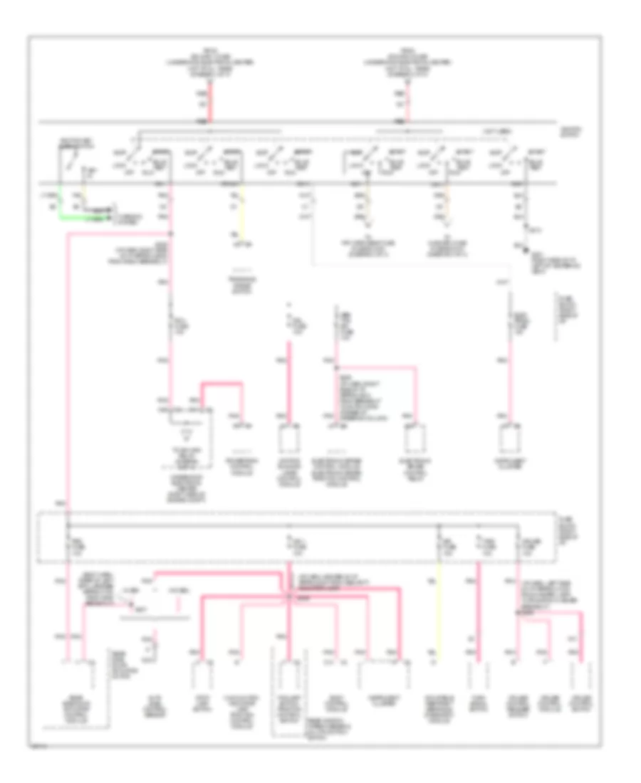
Power Distribution Wiring Diagram (3 of 4) for Oldsmobile Silhouette GL 1997
 https://portal-diagnostov.com/license.html
Automotive Electricians Portal FZCO
Automotive Electricians Portal FZCO
https://portal-diagnostov.com/license.html
https://portal-diagnostov.com/license.html
Automotive Electricians Portal FZCO
Automotive Electricians Portal FZCOList of elements for Power Distribution Wiring Diagram (3 of 4) for Oldsmobile Silhouette GL 1997:
- (body harn, rear of left b-pillar base approx 7cm from g308 breakout)
- (i/p harn, center of i/p approx 8cm from security indicator lamp)
- (i/p harn, left side of i/p approx 41cm from hazard lamp/ turn signal flasher breakout) s266
- (not used)
- A13
- Abs/ tcs ign fuse 10a
- Acc
- Acc 1
- Auto level control sensor
- Body control module
- Bulb test
- C10
- C13
- Crank
- Cruise control module
- Cruise control release switch
- Cruise control switch
- Cruise fuse 10a
- D11
- Daytime running lamps control module
- Drl fuse 10a
- Elec prndl fuse 10a
- Electronic brake control module/ electronic brake traction control module
- Electronic brake control relay
- Foglamp switch/ traction control switch
- From ign main 1 fuse (underhood electrical center) (hot at all times) (diagram 1 of 4)
- From ign main 2 fuse (underhood electrical center) (hot at all times) (diagram 1 of 4)
- Fuse block (right side of i/p)
- G201 (right side of i/p, left of heater-a/c vent)
- Gnd
- Ign 0
- Ign 1
- Ign 1 fuse 10a
- Ign 3
- Ignition key alarm switch
- Ignition switch
- Inflatable restraint sensing & diagnostic module
- Instrument cluster
- Key in
- Lock
- Malfunction indicator lamp traction control module
- Nca
- Off
- Pcm fuse 10a
- Pnk
- Powertrain control module
- Psd fuse 10a
- Rear side door actuator control module
- Rear side door actuator motor
- Rear window wiper/washer & multifunction switch
- Red
- Run
- S209
- S213
- S228 (i/p harn, right side of i/p approx 25cm from radio breakout)
- S239 (i/p harn, right side of i/p approx 8cm from breakout to 48-pin conn at base of steering column)
- S337
- Sir fuse 15a
- Start
- Stop lamp switch
- T/sig fuse 10a
- Tan
- To frt wpr/wshr fuse (fuse block) (diagram 4 of 4)
- To hvac/drl fuse (fuse block) (diagram 4 of 4)
- To ign main relay (diagram 2 of 4)
- Transaxle range switch
- Turn signal switch
- Underhood electrical center (right side of engine compt)
- W/ e58
- W/o e58
- Warning system
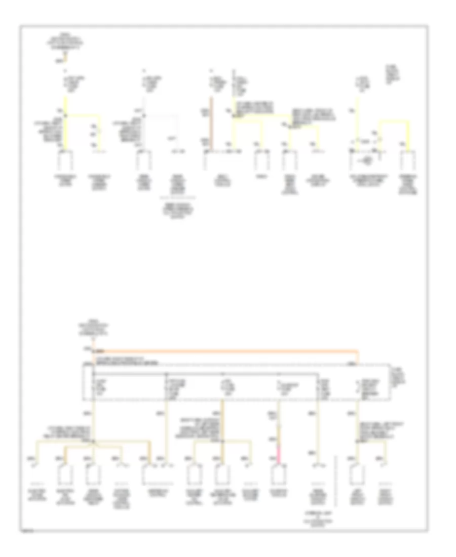
Power Distribution Wiring Diagram (4 of 4) for Oldsmobile Silhouette GL 1997
 https://portal-diagnostov.com/license.html
Automotive Electricians Portal FZCO
Automotive Electricians Portal FZCO
https://portal-diagnostov.com/license.html
https://portal-diagnostov.com/license.html
Automotive Electricians Portal FZCO
Automotive Electricians Portal FZCOList of elements for Power Distribution Wiring Diagram (4 of 4) for Oldsmobile Silhouette GL 1997:
- (body harn, front of right b-pillar approx 15cm from srs module breakout) s316
- (body harn, in front of left rear wheelhouse approx 48cm from left rear side door jamb switch) s345
- (body harn, left front door approx 32cm from seat belt switch breakout) s307
- (i/p harn, center of i/p approx 4cm from security indicator) s227
- (i/p harn, right side of i/p approx 16cm from relay center breakout) s264
- Auxiliary blower motor
- Auxiliary heater- a/c control
- Auxiliary temperature valve actuator
- Bcm prgrm fuse 10a
- Body control module
- C205
- Daytime running lamps control module
- Driver information display
- Electric air inlet actuator
- Electric slave actuator
- From ignition switch (hot in acc or run) (diagram 3 of 4)
- From ignition switch (hot in run) (diagram 3 of 4)
- Frt hvac low/med blwr fuse 25a
- Frt wpr/ wshr fuse 25a
- Fuse block (right side of i/p)
- Heater-a/c control
- Hvac/ drl fuse 10a
- Inflatable retraint steering wheel module coil
- Interior lamp & multifunction switch
- Left front window switch
- Mall/ radio/ dic fuse 10a
- Pnk
- Pwr qtr vent fuse 10a
- Pwr wdo/ rr vent circuit breaker 30a
- Radio
- Radio rear seat audio control
- Rear quarter window switch
- Rear window defogger relay
- Rear window wiper motor
- Rear window wiper/ washer switch
- Rear window wiper/washer & multifunction switch
- Right front window switch
- Rr hvac fuse 25a
- Rr wpr/ wshr fuse 20a
- S245 (i/p harn, right side of i/p approx 5cm from radio breakout)
- S249 (i/p harn, right side of i/p approx 14cm bulkhead grommet)
- S268
- Steering wheel radio control switches
- Sunroof fuse 20a
- Sunroof module
- Swc accy fuse 2a
- Windshield wiper motor
- Windshield wiper/ washer switch

 Čeština
 Dansk
Dansk Deutsch
 Ελληνικά
 English
 English
 Español
 Suomi
Suomi Français
 Français
 עברית
עברית Hrvatski
 Magyar
 Italiano
 한국어
한국어 Nederlands
 Polski
 Português
 Português
 Română
 Русский
 Slovenčina
 Slovenščina
 Svenska
 Türkçe
 中文 (中国)
